EP1008788A2 - Gebläseluftvorrichtung - Google Patents
Gebläseluftvorrichtung Download PDFInfo
- Publication number
- EP1008788A2 EP1008788A2 EP99124226A EP99124226A EP1008788A2 EP 1008788 A2 EP1008788 A2 EP 1008788A2 EP 99124226 A EP99124226 A EP 99124226A EP 99124226 A EP99124226 A EP 99124226A EP 1008788 A2 EP1008788 A2 EP 1008788A2
- Authority
- EP
- European Patent Office
- Prior art keywords
- air
- valve member
- control passage
- air flow
- flow path
- Prior art date
- Legal status (The legal status is an assumption and is not a legal conclusion. Google has not performed a legal analysis and makes no representation as to the accuracy of the status listed.)
- Withdrawn
Links
- 238000004891 communication Methods 0.000 claims abstract description 7
- 230000000903 blocking effect Effects 0.000 claims description 4
- 230000009471 action Effects 0.000 claims description 2
- 239000003570 air Substances 0.000 description 113
- 239000012080 ambient air Substances 0.000 description 6
- 238000010276 construction Methods 0.000 description 2
- 238000001035 drying Methods 0.000 description 2
- 238000009434 installation Methods 0.000 description 2
- 239000000463 material Substances 0.000 description 2
- 238000000034 method Methods 0.000 description 2
- 241000239290 Araneae Species 0.000 description 1
- 239000004677 Nylon Substances 0.000 description 1
- 239000000853 adhesive Substances 0.000 description 1
- 230000001070 adhesive effect Effects 0.000 description 1
- 238000004140 cleaning Methods 0.000 description 1
- 238000001816 cooling Methods 0.000 description 1
- 230000000694 effects Effects 0.000 description 1
- 230000036541 health Effects 0.000 description 1
- 238000004519 manufacturing process Methods 0.000 description 1
- 230000007246 mechanism Effects 0.000 description 1
- 238000012986 modification Methods 0.000 description 1
- 230000004048 modification Effects 0.000 description 1
- 229920001778 nylon Polymers 0.000 description 1
- 229920002635 polyurethane Polymers 0.000 description 1
- 239000004814 polyurethane Substances 0.000 description 1
- 230000008569 process Effects 0.000 description 1
- 238000007789 sealing Methods 0.000 description 1
- 230000011664 signaling Effects 0.000 description 1
- 230000036558 skin tension Effects 0.000 description 1
- 210000003813 thumb Anatomy 0.000 description 1
- 238000011144 upstream manufacturing Methods 0.000 description 1
- 238000003466 welding Methods 0.000 description 1
Images




Classifications
-
- F—MECHANICAL ENGINEERING; LIGHTING; HEATING; WEAPONS; BLASTING
- F16—ENGINEERING ELEMENTS AND UNITS; GENERAL MEASURES FOR PRODUCING AND MAINTAINING EFFECTIVE FUNCTIONING OF MACHINES OR INSTALLATIONS; THERMAL INSULATION IN GENERAL
- F16K—VALVES; TAPS; COCKS; ACTUATING-FLOATS; DEVICES FOR VENTING OR AERATING
- F16K7/00—Diaphragm valves or cut-off apparatus, e.g. with a member deformed, but not moved bodily, to close the passage ; Pinch valves
- F16K7/12—Diaphragm valves or cut-off apparatus, e.g. with a member deformed, but not moved bodily, to close the passage ; Pinch valves with flat, dished, or bowl-shaped diaphragm
- F16K7/14—Diaphragm valves or cut-off apparatus, e.g. with a member deformed, but not moved bodily, to close the passage ; Pinch valves with flat, dished, or bowl-shaped diaphragm arranged to be deformed against a flat seat
- F16K7/17—Diaphragm valves or cut-off apparatus, e.g. with a member deformed, but not moved bodily, to close the passage ; Pinch valves with flat, dished, or bowl-shaped diaphragm arranged to be deformed against a flat seat the diaphragm being actuated by fluid pressure
-
- F—MECHANICAL ENGINEERING; LIGHTING; HEATING; WEAPONS; BLASTING
- F16—ENGINEERING ELEMENTS AND UNITS; GENERAL MEASURES FOR PRODUCING AND MAINTAINING EFFECTIVE FUNCTIONING OF MACHINES OR INSTALLATIONS; THERMAL INSULATION IN GENERAL
- F16K—VALVES; TAPS; COCKS; ACTUATING-FLOATS; DEVICES FOR VENTING OR AERATING
- F16K7/00—Diaphragm valves or cut-off apparatus, e.g. with a member deformed, but not moved bodily, to close the passage ; Pinch valves
- F16K7/10—Diaphragm valves or cut-off apparatus, e.g. with a member deformed, but not moved bodily, to close the passage ; Pinch valves with inflatable member
Definitions
- This invention relates to a blown air apparatus.
- Blown air apparatus are used as an alternative in industry, to compressed air which tends to be expensive in terms of production and compliance with health and safety considerations. Blown air is used for examples, for drying, cleaning and the like.
- Conventionally blown air apparatus have had positionally fixed nozzle air discharge outlets.
- Hand held air "guns” have conventionally used compressed air with there being a control valve adjacent the discharge nozzle.
- a blown air apparatus with a control valve adjacent the discharge nozzle would be bulky because blown air discharge nozzles need to be larger than their compressed air counterparts in order to achieve to same air flow at lower pressures. Consequently, a control valve for such larger nozzle would add even more bulk, making the hand held device unwieldy.
- any bulky control valve located remotely from the hand held discharge means.
- valve member arrangement may thus be of simple bag-like construction, and is inexpensive to produce whilst being inherently very reliable.
- the means to blow the air is located downstream of the valve member, the chamber of the valve member being connected to the blown air and being inflatable by the blown air when the control passage is closed, and being deflated when the control passage is open.
- control means may readily be positioned remotely from the air outlet so that the apparatus lends itself for use for where the air outlet is a hand held blown air discharge means.
- the means to blow the air may be located upsteam of the valve member, the valve member being located in a housing in the air flow path, the control passage communicating with an auxiliary air source which is at a pressure greater than that in the housing, the valve member being inflatable by air from the auxiliary air source when the control passage is open.
- control passage is also in restricted communication with air in the air flow path so that when the control passage is closed, air from the chamber of the valve member may flow into the air flow path so that the valve member deflates.
- valve member when inflated, may close the air flow path by blocking the air flow path, or may be used in conjunction with a slave valve which is operable to open or close the air flow path, the valve member when inflated acting to operate the slave valve to open the air flow path.
- the control passage which extends from the valve member may be opened and closed by many different means.
- the control passage is opened and closed by the action of an electrically operated means such as a solenoid operated valve.
- an electrically operated means such as a solenoid operated valve.
- a solenoid operated valve tend to be bulky and heavy, by virtue of the invention, this may conveniently be positioned remotely from the air outlet which may be a hand held discharge means, so that the manoeuvrability of the discharge means is substantially unaffected, although it will be appreciated that a control line i.e. one or more electrical cables, may need to extend to the discharge means where provided, and a switch device or other control would be required located at or adjacent to the discharge means to operate the solenoid valve or other electrically operated means from the discharge means.
- control passage may extend towards the discharge means and be openable and closable by a manual operation at a position located at or adjacent the discharge means.
- control passage may be opened and closed by the operation of an auxiliary valve member which includes an auxiliary chamber having at least one flexible wall part, and there being an auxiliary control passage in communication with the auxiliary chamber and the auxiliary chamber being connected to the air source, whereby the auxiliary valve member is operated by being inflated by air from the air source when the auxiliary control passage is closed, and is operated by deflating when the auxiliary control passage is opened.
- an auxiliary valve member which includes an auxiliary chamber having at least one flexible wall part, and there being an auxiliary control passage in communication with the auxiliary chamber and the auxiliary chamber being connected to the air source, whereby the auxiliary valve member is operated by being inflated by air from the air source when the auxiliary control passage is closed, and is operated by deflating when the auxiliary control passage is opened.
- Such auxiliary valve member when inflated is preferably operable to open the control passage of the valve member, by acting on a slave valve member which is moved to open the control passage.
- air flowing to the air outlet may be air for use, i.e. blown air, but alternatively the air outlet may be a vent through which the air flow is vented in preference the air flow being supplied for use.
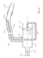
- a blown air apparatus 10 including a source 11 of blown air, from an air blower (not shown).
- the blown air enters a control means 14 through an inlet which in this case is a spigot 15, and exits the control means 14 for use, through an outlet which again in this example is a spigot 16, which outlet 16 is connected to a conduit 18 which extends to an air outlet or discharge means 20, which in this example includes a hand held nozzle.
- the control means 14 controls the flow of air to the discharge nozzle 20 and including a valve member 22 which is operable either to block the air path from the inlet 15 to the outlet 16, or to permit air flow.
- the valve member 22 including a chamber C bounded by a pair of generally circular flexible walls 23,24, which are connected e.g. by welding, adhesive or the like, around their circumferences 25, so as to form a single cell bellows or bag.
- the walls 23,24 need not be circular in another embodiment, or a valve member 22 having suitable characteristics to operate as described below for this and the other embodiments, may be of another configuration e.g. having only part of the chamber C bounded by a flexible wall.
- the wall 24 which faces the incoming air flow through the inlet 15 has an opening, in this example arranged generally centrally, which receives a tube 28 of small diameter compared with that of the inlet 15.
- the tube 28 may be restricted as required, e.g. with an orifice 28 a to control the flow of air into and from the chamber C as hereinafter described.
- the opposite wall 23 of the valve member 22 also has an opening, again arranged generally centrally in this embodiment, which receives a further tube 30 which is a control passage, which again is in communication with the chamber C.
- the valve member 22 is positioned so that when air may flow from the inlet 15 through the chamber C, along the control passage to a vent 31 (hidden in figure 2), blown air may flow past the valve member 22 to the outlet 16 and hence to the discharge nozzle 20 for use. However, if the air flow from the chamber C is prevented by the control passage 30 being blocked, the valve member 22 will inflate, and prevent the air flow to the discharge nozzle 20.
- valve member 22 is able to inflate as the pressure working on each of the walls 23,24 of the valve member 22 will create a skin tension which is able to overcome the air pressure in the inlet 15.
- the flexible walls 23,24 are made from a material of woven nylon which is totally encapsulated in polyurethane, although other suitable materials may be used. Also, for more effective sealing, there is provided a backing support wall 40 against which the flexible wall 23 which faces away from the inlet 15 bears when the valve member 22 is inflated.
- the control passage 30 extends through the backing support wall 40.
- the backing support wall 40 also serves to provide a plenum 41 within the control means 14, with which the outlet 16 communicates.
- Various means may be utilised to open and close the control passage 30, to operate the valve member 22 depending on the use to which the apparatus 10 is put.
- a solenoid operated valve 32 is illustrated.
- the valve 32 may be of the kind which is normally closed until an electrical signal is received, so that the valve member 22 is normally inflated to close the air supply to the discharge nozzle 20, or in another arrangement though, where an air supply is required until a control is operated to interrupt the air supply, the solenoid valve 32 may be of the kind which is normally open, so that the control passage 30 is normally open and the valve member 22 is deflated.
- valve member 22 instead of blocking the air flow when inflated, may be arranged to act through a slave valve such as a flap valve, so that when inflated, the valve member 22 permits air flow to the discharge nozzle 20 or other discharge means, and when deflated the slave valve blocks the air flow.
- a slave valve such as a flap valve
- valve 32 may be controlled by a control such as for example for a hand held nozzle, a simple switch at the discharge nozzle.
- a control such as for example for a hand held nozzle, a simple switch at the discharge nozzle.
- an electrical line will be required between the control at the discharge nozzle 20 and the electrically operated means of the control means 14.
- the solenoid valve 32 is particularly useful when the air supply is used in a fixed installation in which case some other remote signalling arrangement may be utilised e.g. a control signal may be provided to solenoid valve 32 from, say, a photocell at the fixed installation.
- valve member 22 again opens or closes an air flow, but when open, the air flow is vented to an air outlet preferentially to being discharged for use.
- the valve member 22 acts as a dump valve.
- a fan or blower F draws in air through a blower inlet 26, and blows the air from a blower outlet 27 which is connected to a valve inlet 15 e.g. by a flexible hose H.
- the inlet 15 extends to a passage 45 along which the air may flow, when the valve member 22 is deflated, to the valve member 22 and hence from the control means 14 to a vent 29. From the outlet 16 from the passage 45 there extends a conduit 18 which extends to the discharge nozzle 20 or other discharge means.
- the passage 45 of the control means 14 is of significantly greater diameter than the diameter of the conduit 18, and the entrance to the conduit 18 is arranged at a sharp angle, 90° in this example, to the natural air flow direction straight along the passage 45.
- the air flow will be to the vent 29.
- valve member 22 When the valve member 22 is inflated, as the control passage 30 thereof is closed, air flow to the vent 29 will be prevented and thus all the air flow will be to the discharge nozzle 20 along the conduit 45.
- a relief valve 32 is provided to relieve pressure in the passage 45, if for example the discharge nozzle 20 is blocked.
- control passage 30 may be controlled by a solenoid or other electrically operated means, such as solenoid operated valve 32 in the figure 2 arrangement, preferably the air flow through the control passage 30 is controlled by a manually operated means.
- the control passage 30 extends, within the delivery conduit 18 in this example, to the discharge nozzle 20, where the control passage 18 opens to an opening 48.
- the opening 48 may be positioned so that an operative may manually close the opening 48 e.g. with a thumb, with the effect that the valve member 22 will be inflated and all the blown air will be delivered to the discharge nozzle 20 for use.
- valve member 22 operating through a slave valve, so that when inflated, the air flow to the vent 29 is opened, and when the valve member 22 is deflated, air flow to the vent 29 is blocked.
- valve member 22 instead of electrically operated and/or manually operated means being provided to open/close the control passage 30, another valve member, like valve member 22 may be provided to achieve this, as illustrated in figure 5.
- valve member 22 controls air flow from the inlet 15 to the discharge nozzle 20, but could be applied to a figures 3 and 4 type arrangement in which the valve member 22 controls air flow to a vent 29.
- the control passage 30 of the valve member 22 extends to a vent V, and a slave valve 51, similar in construction to valve member 22, is operative to control the air flow along the control passage 30 to the vent V.
- the slave valve 51 operates a spring loaded flap valve 53 which is acted upon by an auxiliary valve member 55.
- an auxiliary valve member 55 When an auxiliary valve member 55 is deflated the spring of the flap valve 53 acts to move the flap valve 53 to close the air flow to the vent V, so that (main) control valve 22 inflates.
- the auxiliary valve 55 member inflates, the force of the spring of the flap valve 53 is overcome to open the vent V to allow air flow along the control passage 30 from the (main) valve member 22 to flow to the vent V, so that the (main) valve member 22 deflates.
- the auxiliary valve member 55 is provided with supply air from the inlet 15 via a supply conduit 58 which is constructed by an orifice 58 a , and an auxiliary control passage 59 from the auxiliary valve member 55 extends to the discharge nozzle 20, preferably at least partly within the delivery conduit 18, so that an opening 48 of the auxiliary control passage 59 may be opened and closed by a manual operation similar to that described with reference to figure 2.
- a manual operation similar to that described with reference to figure 2.
- the (main) valve member 22 may inflate or allow deflation to permit or prevent flow of the air to the discharge nozzle 20.
- some other mechanism to enable a slave valve 51 to control the flow of air along the control passage 30 of the main valve 22 may be provided if desired.
- FIG 6 a fourth embodiment of the invention is shown, with similar parts to those in the previous embodiments being labelled by the same reference signs.
- the blower means F to blow the air is located upstream of the valve member 22.
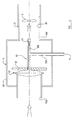
- the control means 14 includes a housing 60 which has an inlet 15a open to a source 11 of ambient air rather than blown air as in the previous embodiments, and an outlet 16a which is connected to a blower inlet 26.
- the blower F is connected to an air outlet (not shown).
- the valve member 22 is located in the housing 60 and air may be drawn by the blower F to flow from the housing inlet 15a past the valve member 22 when the valve member 22 is deflated, through the housing 60 to the housing outlet 16a. When the valve member 22 is inflated though, air flow into the housing 60 is prevented.
- valve member 22 when inflated, acts between a backing support wall 40 located in the housing 60, and for example supported in the housing 60 by a spider type support structure, and the housing inlet 15a, to seal the housing inlet 15a and prevent the flow of air into the housing 60.
- a control passage 30 extends from and communicates with the chamber C, the control passage 30 having a first branch 30a which extends to an auxiliary air source, in this case a source of ambient air V1, and a second branch 30b which opens into the air flow in the housing 60, via a throttled or otherwise constricted opening V2.
- auxiliary air source in this case a source of ambient air V1
- second branch 30b which opens into the air flow in the housing 60, via a throttled or otherwise constricted opening V2.
- the control passage 30 may be opened or closed manually or by a solenoid or other electrically actuated or other means.
- the embodiments of figures 1 to 5 lend themselves particularly to arrangements in which the discharged blown air is used, e.g. for drying, cooling or the like, in a factory environment
- the arrangement of figure 6 lends itself more particularly to an arrangement in which the blown air is discharged to atmosphere and the air inlet 15a to the housing 60 is used as a source of vacuum i.e. for sucking air.
- the arrangements of the figures 1 to 5 embodiments may be adapted for use in providing a source of vacuum and the arrangement of figure 6 may be adapted for supplying blown air as desired.
Landscapes
- Engineering & Computer Science (AREA)
- General Engineering & Computer Science (AREA)
- Mechanical Engineering (AREA)
- Physics & Mathematics (AREA)
- Fluid Mechanics (AREA)
- Massaging Devices (AREA)
- Supply Of Fluid Materials To The Packaging Location (AREA)
- Invalid Beds And Related Equipment (AREA)
Applications Claiming Priority (2)
| Application Number | Priority Date | Filing Date | Title |
|---|---|---|---|
| GB9826916 | 1998-12-09 | ||
| GB9826916A GB2344617A (en) | 1998-12-09 | 1998-12-09 | Blown air apparatus with control valve |
Publications (2)
| Publication Number | Publication Date |
|---|---|
| EP1008788A2 true EP1008788A2 (de) | 2000-06-14 |
| EP1008788A3 EP1008788A3 (de) | 2001-03-28 |
Family
ID=10843796
Family Applications (1)
| Application Number | Title | Priority Date | Filing Date |
|---|---|---|---|
| EP99124226A Withdrawn EP1008788A3 (de) | 1998-12-09 | 1999-12-03 | Gebläseluftvorrichtung |
Country Status (2)
| Country | Link |
|---|---|
| EP (1) | EP1008788A3 (de) |
| GB (1) | GB2344617A (de) |
Cited By (1)
| Publication number | Priority date | Publication date | Assignee | Title |
|---|---|---|---|---|
| WO2024223106A1 (de) * | 2023-04-25 | 2024-10-31 | Carl Zeiss Smt Gmbh | Verfahren zum trocknen einer medienführenden leitung, trocknungseinrichtung und lithographiesystem |
Family Cites Families (9)
| Publication number | Priority date | Publication date | Assignee | Title |
|---|---|---|---|---|
| GB829973A (en) * | 1956-12-04 | 1960-03-09 | Garrett Corp | Fluid valve |
| US3275270A (en) * | 1965-03-17 | 1966-09-27 | Bell Aerospace Corp | Aircraft with ground effect type landing gear |
| FR2129063A5 (de) * | 1971-03-12 | 1972-10-27 | Pronal Sa | |
| DE2256246C3 (de) * | 1971-11-18 | 1979-08-09 | Joulin Sema S.A., Etampes (Frankreich) | Automatisches Verschlußorgan für die Saugöffnungen eines Saugförderers |
| FR2266837A1 (en) * | 1974-04-08 | 1975-10-31 | Superflexit | Pilot controlled non-return valve - has two membranes forming chamber with inner pilot pressure tube |
| US4185806A (en) * | 1976-09-01 | 1980-01-29 | Dremann George H | Fluid material flow control valve |
| GB2128297B (en) * | 1982-10-07 | 1986-07-02 | Vosper Hovermarine Ltd | Fluid flow control systems |
| GB2134220A (en) * | 1983-01-11 | 1984-08-08 | Colin Badham | Improvements relating to valves for fluid materials |
| US4600144A (en) * | 1983-11-25 | 1986-07-15 | Alex Zelczer | Zone control apparatus for central heating and/or cooling systems |
-
1998
- 1998-12-09 GB GB9826916A patent/GB2344617A/en not_active Withdrawn
-
1999
- 1999-12-03 EP EP99124226A patent/EP1008788A3/de not_active Withdrawn
Cited By (1)
| Publication number | Priority date | Publication date | Assignee | Title |
|---|---|---|---|---|
| WO2024223106A1 (de) * | 2023-04-25 | 2024-10-31 | Carl Zeiss Smt Gmbh | Verfahren zum trocknen einer medienführenden leitung, trocknungseinrichtung und lithographiesystem |
Also Published As
| Publication number | Publication date |
|---|---|
| GB2344617A (en) | 2000-06-14 |
| GB9826916D0 (en) | 1999-01-27 |
| EP1008788A3 (de) | 2001-03-28 |
Similar Documents
| Publication | Publication Date | Title |
|---|---|---|
| US5253687A (en) | Vehicle central tire inflation system | |
| KR0152448B1 (ko) | 차량타이어 팽창시스템용 통기구멍 | |
| EP0046275B1 (de) | Ansaugvorrichtung für das Aufblasen flexibler Gegenstände | |
| CN201586976U (zh) | 物料处理系统 | |
| US6709246B2 (en) | Inflation/deflation device having spring biased value | |
| US4045835A (en) | Power deflator mechanism for scuba buoyancy vests | |
| US7073545B2 (en) | Inflation and deflation apparatus | |
| US4566862A (en) | Fluid apparatus and methods, as for inflating inflatable structures | |
| US5497520A (en) | Inflatable leg and foot support | |
| US20070080514A1 (en) | Pneumatic suspension unit for a vehicle | |
| CA2596504A1 (en) | Inflatable device with recessed fluid controller and modified adjustment device | |
| US3933177A (en) | Manually controlled air inflator adaptor | |
| CA2309065C (en) | Infusion system with improved control valve | |
| EP1008788A2 (de) | Gebläseluftvorrichtung | |
| US5924166A (en) | Cleaning gun adjustable to blowing and suction functions | |
| US5341959A (en) | Bag emptying arrangement | |
| NO953259L (no) | Apparat for å kontrollere strömmen av oppblåsing-fluid inn i en luftpose | |
| EP3899332B1 (de) | Ventil zum aufblasen und entleeren eines aufblasbaren elements | |
| GB2257766A (en) | Inflatable pipe plug | |
| EP0743021A3 (de) | Schutzvorrichtung für eine von einem Fördermittel oder -tier transportierte Person | |
| WO1999041185A3 (de) | Handgesteuertes hebegerät mit einem pneumatischen hubantrieb | |
| US3812930A (en) | Air cushion vehicle control device | |
| GB2268164A (en) | Bag emptying. | |
| JPH1163260A (ja) | 弁構造 | |
| GB2284249A (en) | Pneumatic valve |
Legal Events
| Date | Code | Title | Description |
|---|---|---|---|
| PUAI | Public reference made under article 153(3) epc to a published international application that has entered the european phase |
Free format text: ORIGINAL CODE: 0009012 |
|
| AK | Designated contracting states |
Kind code of ref document: A2 Designated state(s): AT BE CH CY DE DK ES FI FR GB GR IE IT LI LU MC NL PT SE |
|
| AX | Request for extension of the european patent |
Free format text: AL;LT;LV;MK;RO;SI |
|
| PUAL | Search report despatched |
Free format text: ORIGINAL CODE: 0009013 |
|
| AK | Designated contracting states |
Kind code of ref document: A3 Designated state(s): AT BE CH CY DE DK ES FI FR GB GR IE IT LI LU MC NL PT SE |
|
| AX | Request for extension of the european patent |
Free format text: AL;LT;LV;MK;RO;SI |
|
| AKX | Designation fees paid |
Free format text: AT BE CH CY DE DK ES FI FR GB GR IE IT LI LU MC NL PT SE |
|
| STAA | Information on the status of an ep patent application or granted ep patent |
Free format text: STATUS: THE APPLICATION IS DEEMED TO BE WITHDRAWN |
|
| 18D | Application deemed to be withdrawn |
Effective date: 20010929 |