EP1008792A2 - Soupape magnétique - Google Patents
Soupape magnétique Download PDFInfo
- Publication number
- EP1008792A2 EP1008792A2 EP99123883A EP99123883A EP1008792A2 EP 1008792 A2 EP1008792 A2 EP 1008792A2 EP 99123883 A EP99123883 A EP 99123883A EP 99123883 A EP99123883 A EP 99123883A EP 1008792 A2 EP1008792 A2 EP 1008792A2
- Authority
- EP
- European Patent Office
- Prior art keywords
- bore
- rod
- valve
- solenoid valve
- spring
- Prior art date
- Legal status (The legal status is an assumption and is not a legal conclusion. Google has not performed a legal analysis and makes no representation as to the accuracy of the status listed.)
- Granted
Links
- 230000005284 excitation Effects 0.000 description 17
- 238000010276 construction Methods 0.000 description 2
- 239000011324 bead Substances 0.000 description 1
- 238000005553 drilling Methods 0.000 description 1
- 230000000694 effects Effects 0.000 description 1
- 238000005516 engineering process Methods 0.000 description 1
Images
Classifications
-
- F—MECHANICAL ENGINEERING; LIGHTING; HEATING; WEAPONS; BLASTING
- F16—ENGINEERING ELEMENTS AND UNITS; GENERAL MEASURES FOR PRODUCING AND MAINTAINING EFFECTIVE FUNCTIONING OF MACHINES OR INSTALLATIONS; THERMAL INSULATION IN GENERAL
- F16K—VALVES; TAPS; COCKS; ACTUATING-FLOATS; DEVICES FOR VENTING OR AERATING
- F16K31/00—Actuating devices; Operating means; Releasing devices
- F16K31/02—Actuating devices; Operating means; Releasing devices electric; magnetic
- F16K31/06—Actuating devices; Operating means; Releasing devices electric; magnetic using a magnet, e.g. diaphragm valves, cutting off by means of a liquid
- F16K31/0644—One-way valve
- F16K31/0655—Lift valves
Definitions
- the invention relates to a solenoid valve according to the preamble of claim 1.
- Solenoid valves of the above type are well known from the prior art. So can for example refer to DE-PS 43 05 987 or DE-PS 196 32 552 that show such solenoid valves. Further solenoid valves show that DE 195 10 288 A1, DE 195 04 246 A1, DE 43 06 847 A1 and DE 195 02 671 A1.
- a force must be applied by an excitation coil to open a solenoid valve on the one hand against the pressure difference prevailing at the valve closing body and on the other hand, must act against the spring force of a closing spring of the solenoid valve.
- the solenoid valve opens, the one prevailing on the valve closing body Pressure difference reduced to zero, must be the one generated by the excitation coil after opening Only act against the spring force of the closing spring. It follows immediately that with large pressure differences from the excitation coil on the valve closing body a large force to open the solenoid valve must be generated, but after Opening the solenoid valve is no longer required in this size.
- DE 40 28 447 A1 discloses a solenoid valve with a Movable valve closing body known, which is assigned to a rod-shaped element and with a magnet armature interacting with the rod-shaped element, the magnet armature extending in the longitudinal direction of the magnet armature, has a continuous bore, a rod-shaped element in the bore is arranged, the rod-shaped element having a first, the valve closing body facing end protrudes from the bore and with the valve closing body is connected, and wherein a spring element is further arranged in the bore.
- the present invention is based on the problem to create a new and inexpensive solenoid valve.
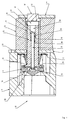
- the magnet armature 15 interacts with a support element 18, which has a valve closing body 19 is assigned.
- a support element 18 which has a valve closing body 19 is assigned.
- the valve closing body is seated 19 on a revolving valve seat 20 on when the excitation coil 13 is de-energized the valve closing body 19 is pressed onto the valve seat 20 by a closing spring 21 and thus held in the closed position of the solenoid valve 10 shown in FIG. 1.
- the Closing spring 21 can e.g. be designed as a conical or helical spring.
- an air gap 24 Between an upper end 22 of the armature 15 and an upper end 23 of the Anchor sleeve 16 is formed with an air gap 24.
- the one of the force to be applied to the excitation coil 13 is maximum when the air gap 24 is minimal.
- this force must be exerted against a valve closing body 19 prevailing pressure difference and act against the spring force of the closing spring 21.
- the solenoid valve of the present has Invention in the armature 15 via a bore 25 which is continuously in Longitudinal direction of the armature 15 extends.
- an elongated arranged rod-shaped element 26 Within the bore 25 is an elongated arranged rod-shaped element 26. With a first, facing the support element 18 End 27 projects rod-shaped element 26 from bore 25.
- Figure 1 can be seen that the rod-shaped element 26 with this end 27 by a Bore of the support member 18 protrudes and a clamping element 28 with the Support element 18 is connected.
- the spring element 29 is supported at one end on a lower shoulder 30 the bore 25 and with another end on a second end 31 of the rod-shaped Elements 26.
- Another paragraph 32 within the bore 25, the above the Paragraph 30 is positioned forms a stop for the second end 31 of the rod-shaped Elements 26
- the already mentioned closing spring 21 of the solenoid valve 10 is between the armature sleeve 16 and the valve closing body 19, wherein the closing spring 21 with a End on the section 17 of the anchor sleeve 16 and with another end on one supports lower section 33 of the armature 15, this section 33 as circumferential bead is formed.
- the excitation coil 13 To open the solenoid valve 10, the excitation coil 13 is activated. The magnetic force provided by the excitation coil 13 pulls the magnet armature 15 counter to the closing force of the closing spring 21 upwards, which on the valve closing body 19 acting closing force is reduced. The valve is in this state still closed, i.e. the valve closing body 19 is still seated on the valve seat 20 When the magnet armature 15 is pulled up further, the magnet armature 15 only has to be pulled are moved against the spring forces of the closing spring 21 and the spring element 29 until the shoulder 32 acting as a stop at the upper end 31 of the rod-shaped element 26 comes to the plant.
- the spring element 29 provided spring force is smaller than that provided by the closing spring 21 Spring force.
- the operation of the Solenoid valve 10 according to the invention that the distance between the paragraph 32 of the Bore 25 and the upper end 31 of the rod-shaped element 26 must be smaller than the total stroke range of the magnet armature 15.
- the solenoid valve 10 according to the invention accordingly needs to open a valve from certain size smaller and cheaper excitation coils than the solenoid valves the state of the art. This reduces the size. They too Working noise of the solenoid valve is positively influenced.
Landscapes
- Engineering & Computer Science (AREA)
- General Engineering & Computer Science (AREA)
- Mechanical Engineering (AREA)
- Magnetically Actuated Valves (AREA)
Applications Claiming Priority (2)
| Application Number | Priority Date | Filing Date | Title |
|---|---|---|---|
| DE1998156488 DE19856488B4 (de) | 1998-12-08 | 1998-12-08 | Magnetventil |
| DE19856488 | 1998-12-08 |
Publications (3)
| Publication Number | Publication Date |
|---|---|
| EP1008792A2 true EP1008792A2 (fr) | 2000-06-14 |
| EP1008792A3 EP1008792A3 (fr) | 2001-09-05 |
| EP1008792B1 EP1008792B1 (fr) | 2007-04-18 |
Family
ID=7890313
Family Applications (1)
| Application Number | Title | Priority Date | Filing Date |
|---|---|---|---|
| EP99123883A Expired - Lifetime EP1008792B1 (fr) | 1998-12-08 | 1999-12-02 | Soupape magnétique |
Country Status (2)
| Country | Link |
|---|---|
| EP (1) | EP1008792B1 (fr) |
| DE (2) | DE19856488B4 (fr) |
Families Citing this family (2)
| Publication number | Priority date | Publication date | Assignee | Title |
|---|---|---|---|---|
| US6505812B1 (en) * | 2000-11-17 | 2003-01-14 | Mks Instruments, Inc. | Solenoid valve |
| DE102005014100B4 (de) * | 2004-07-15 | 2014-01-02 | Continental Teves Ag & Co. Ohg | Elektromagnetventil, insbesondere für schlupfgeregelte Kraftfahrzeugbremsanlagen |
Citations (7)
| Publication number | Priority date | Publication date | Assignee | Title |
|---|---|---|---|---|
| DE4028447A1 (de) | 1990-09-07 | 1992-03-12 | Teves Gmbh Alfred | Elektromagnetventil fuer hydraulische bremsanlagen mit schlupfregelung |
| DE4305987C1 (de) | 1993-02-26 | 1993-11-25 | Honeywell Bv | Magnetventil mit Schmutzfalle |
| DE4306847A1 (de) | 1993-03-01 | 1994-09-08 | Frank Pruefer | Elektromagnetisch betätigtes Ventil |
| DE19502671A1 (de) | 1995-01-20 | 1996-08-01 | Mannesmann Ag | Elektromagnetantrieb, insbesondere für Elektromagnetventile als Stellglieder für Fluide |
| DE19504246A1 (de) | 1995-02-09 | 1996-08-14 | Teves Gmbh Alfred | Elektromagnetventil mit Druckbegrenzungsfunktion, insbesondere für hydraulische Kraftfahrzeugbremsanlagen mit Schlupfregelung und/oder automatischem Bremseneingriff zur Fahrdynamikregelung |
| DE19510288A1 (de) | 1995-03-22 | 1996-09-26 | Teves Gmbh Alfred | Elektromagnetventil mit Druckbegrenzungsfunktion, isnbesondere für hydraulische Kraftfahrzeug-Bremsanlageen mit Schlupfregelung und/oder automatischem Bremseneingriff zur Fahrdynamikregelung |
| DE19632552C1 (de) | 1996-08-13 | 1997-12-11 | Honeywell Bv | Einstellvorrichtung für den magnetischen Widerstand eines Magnetkreises in einem Magnetventil |
Family Cites Families (2)
| Publication number | Priority date | Publication date | Assignee | Title |
|---|---|---|---|---|
| US4008876A (en) * | 1975-06-09 | 1977-02-22 | The Singer Company | Solenoid valve |
| US5209455A (en) * | 1990-11-19 | 1993-05-11 | Mitsubishi Materials Corporation | Valve and solenoid valve operated by very small force |
-
1998
- 1998-12-08 DE DE1998156488 patent/DE19856488B4/de not_active Expired - Lifetime
-
1999
- 1999-12-02 DE DE59914299T patent/DE59914299D1/de not_active Expired - Lifetime
- 1999-12-02 EP EP99123883A patent/EP1008792B1/fr not_active Expired - Lifetime
Patent Citations (7)
| Publication number | Priority date | Publication date | Assignee | Title |
|---|---|---|---|---|
| DE4028447A1 (de) | 1990-09-07 | 1992-03-12 | Teves Gmbh Alfred | Elektromagnetventil fuer hydraulische bremsanlagen mit schlupfregelung |
| DE4305987C1 (de) | 1993-02-26 | 1993-11-25 | Honeywell Bv | Magnetventil mit Schmutzfalle |
| DE4306847A1 (de) | 1993-03-01 | 1994-09-08 | Frank Pruefer | Elektromagnetisch betätigtes Ventil |
| DE19502671A1 (de) | 1995-01-20 | 1996-08-01 | Mannesmann Ag | Elektromagnetantrieb, insbesondere für Elektromagnetventile als Stellglieder für Fluide |
| DE19504246A1 (de) | 1995-02-09 | 1996-08-14 | Teves Gmbh Alfred | Elektromagnetventil mit Druckbegrenzungsfunktion, insbesondere für hydraulische Kraftfahrzeugbremsanlagen mit Schlupfregelung und/oder automatischem Bremseneingriff zur Fahrdynamikregelung |
| DE19510288A1 (de) | 1995-03-22 | 1996-09-26 | Teves Gmbh Alfred | Elektromagnetventil mit Druckbegrenzungsfunktion, isnbesondere für hydraulische Kraftfahrzeug-Bremsanlageen mit Schlupfregelung und/oder automatischem Bremseneingriff zur Fahrdynamikregelung |
| DE19632552C1 (de) | 1996-08-13 | 1997-12-11 | Honeywell Bv | Einstellvorrichtung für den magnetischen Widerstand eines Magnetkreises in einem Magnetventil |
Also Published As
| Publication number | Publication date |
|---|---|
| DE19856488B4 (de) | 2004-02-26 |
| DE19856488A1 (de) | 2000-06-29 |
| DE59914299D1 (de) | 2007-05-31 |
| EP1008792A3 (fr) | 2001-09-05 |
| EP1008792B1 (fr) | 2007-04-18 |
Similar Documents
| Publication | Publication Date | Title |
|---|---|---|
| DE3802648C2 (fr) | ||
| EP1084358B1 (fr) | Double vanne de securite magnetique | |
| DE102009012688B3 (de) | Ventil zum Einblasen von Gas | |
| DE2315425A1 (de) | Elektromagnetisch betaetigtes wegeventil | |
| EP0681128A1 (fr) | Electrovanne | |
| DE102012218593A1 (de) | Ventil für eine Pumpe | |
| DE69208112T2 (de) | Durchflussregler | |
| DE4428869C2 (de) | Magnetventil | |
| DE2306480A1 (de) | Schaltbares, insbesondere elektromagnetisch schaltbares, hochdruckventil | |
| DE10046939B4 (de) | Tauchankersystem mit Anschlagdämpfung | |
| DE19716856B4 (de) | Baueinheit für ein Hydraulikventil | |
| DE3317226C2 (fr) | ||
| DE2855902A1 (de) | Elektromagnetisch betaetigbares 3/2-wegeventil, insbesondere zur fernsteuerung von einseitig mit einem fluid beaufschlagbaren vorrichtungen | |
| DE2701580A1 (de) | Druckventil | |
| DE19856488B4 (de) | Magnetventil | |
| DE102007001741A1 (de) | Vorrichtung zur linearen Bewegung eines Ventilgliedes | |
| EP1601869B1 (fr) | Soupape comportant un element ressort pour un injecteur de carburant | |
| DE3310785A1 (de) | Sitzventil | |
| DE10031873B4 (de) | Hydraulisches Ventil | |
| EP0535394A1 (fr) | Clapet électromagnétique pour gaz liquifiés à basses températures | |
| DE2923648C2 (de) | Elektromagnetisch betätigtes Fluid- Stellventil | |
| EP0987478B1 (fr) | Soupape électromagnétique | |
| WO2004036329A2 (fr) | Soupape de regulation de pression | |
| EP1577596B1 (fr) | Dispositif de commutation | |
| DE19938921A1 (de) | Einspritzventil für eine Verbrennungskraftmaschine |
Legal Events
| Date | Code | Title | Description |
|---|---|---|---|
| PUAI | Public reference made under article 153(3) epc to a published international application that has entered the european phase |
Free format text: ORIGINAL CODE: 0009012 |
|
| AK | Designated contracting states |
Kind code of ref document: A2 Designated state(s): AT BE CH CY DE DK ES FI FR GB GR IE IT LI LU MC NL PT SE |
|
| AX | Request for extension of the european patent |
Free format text: AL;LT;LV;MK;RO;SI |
|
| PUAL | Search report despatched |
Free format text: ORIGINAL CODE: 0009013 |
|
| AK | Designated contracting states |
Kind code of ref document: A3 Designated state(s): AT BE CH CY DE DK ES FI FR GB GR IE IT LI LU MC NL PT SE |
|
| AX | Request for extension of the european patent |
Free format text: AL;LT;LV;MK;RO;SI |
|
| 17P | Request for examination filed |
Effective date: 20011114 |
|
| AKX | Designation fees paid |
Free format text: DE FR GB IT NL |
|
| 17Q | First examination report despatched |
Effective date: 20040213 |
|
| GRAP | Despatch of communication of intention to grant a patent |
Free format text: ORIGINAL CODE: EPIDOSNIGR1 |
|
| GRAS | Grant fee paid |
Free format text: ORIGINAL CODE: EPIDOSNIGR3 |
|
| GRAA | (expected) grant |
Free format text: ORIGINAL CODE: 0009210 |
|
| AK | Designated contracting states |
Kind code of ref document: B1 Designated state(s): DE FR GB IT NL |
|
| GBT | Gb: translation of ep patent filed (gb section 77(6)(a)/1977) |
Effective date: 20070502 |
|
| REF | Corresponds to: |
Ref document number: 59914299 Country of ref document: DE Date of ref document: 20070531 Kind code of ref document: P |
|
| PLBE | No opposition filed within time limit |
Free format text: ORIGINAL CODE: 0009261 |
|
| STAA | Information on the status of an ep patent application or granted ep patent |
Free format text: STATUS: NO OPPOSITION FILED WITHIN TIME LIMIT |
|
| 26N | No opposition filed |
Effective date: 20080121 |
|
| REG | Reference to a national code |
Ref country code: GB Ref legal event code: 732E |
|
| NLS | Nl: assignments of ep-patents |
Owner name: HONEYWELL TECHNOLOGIES SARL Effective date: 20080618 |
|
| REG | Reference to a national code |
Ref country code: FR Ref legal event code: TP |
|
| PGFP | Annual fee paid to national office [announced via postgrant information from national office to epo] |
Ref country code: GB Payment date: 20141124 Year of fee payment: 16 |
|
| PGFP | Annual fee paid to national office [announced via postgrant information from national office to epo] |
Ref country code: NL Payment date: 20141209 Year of fee payment: 16 |
|
| REG | Reference to a national code |
Ref country code: FR Ref legal event code: PLFP Year of fee payment: 17 |
|
| GBPC | Gb: european patent ceased through non-payment of renewal fee |
Effective date: 20151202 |
|
| REG | Reference to a national code |
Ref country code: NL Ref legal event code: MM Effective date: 20160101 |
|
| PG25 | Lapsed in a contracting state [announced via postgrant information from national office to epo] |
Ref country code: GB Free format text: LAPSE BECAUSE OF NON-PAYMENT OF DUE FEES Effective date: 20151202 Ref country code: NL Free format text: LAPSE BECAUSE OF NON-PAYMENT OF DUE FEES Effective date: 20160101 |
|
| REG | Reference to a national code |
Ref country code: FR Ref legal event code: PLFP Year of fee payment: 18 |
|
| REG | Reference to a national code |
Ref country code: FR Ref legal event code: PLFP Year of fee payment: 19 |
|
| PGFP | Annual fee paid to national office [announced via postgrant information from national office to epo] |
Ref country code: DE Payment date: 20180228 Year of fee payment: 19 |
|
| PGFP | Annual fee paid to national office [announced via postgrant information from national office to epo] |
Ref country code: IT Payment date: 20171220 Year of fee payment: 19 |
|
| PGFP | Annual fee paid to national office [announced via postgrant information from national office to epo] |
Ref country code: FR Payment date: 20181231 Year of fee payment: 20 |
|
| REG | Reference to a national code |
Ref country code: DE Ref legal event code: R119 Ref document number: 59914299 Country of ref document: DE |
|
| PG25 | Lapsed in a contracting state [announced via postgrant information from national office to epo] |
Ref country code: DE Free format text: LAPSE BECAUSE OF NON-PAYMENT OF DUE FEES Effective date: 20190702 Ref country code: IT Free format text: LAPSE BECAUSE OF NON-PAYMENT OF DUE FEES Effective date: 20181202 |