EP1008792B1 - Soupape magnétique - Google Patents
Soupape magnétique Download PDFInfo
- Publication number
- EP1008792B1 EP1008792B1 EP99123883A EP99123883A EP1008792B1 EP 1008792 B1 EP1008792 B1 EP 1008792B1 EP 99123883 A EP99123883 A EP 99123883A EP 99123883 A EP99123883 A EP 99123883A EP 1008792 B1 EP1008792 B1 EP 1008792B1
- Authority
- EP
- European Patent Office
- Prior art keywords
- armature
- spring
- valve
- rod
- solenoid
- Prior art date
- Legal status (The legal status is an assumption and is not a legal conclusion. Google has not performed a legal analysis and makes no representation as to the accuracy of the status listed.)
- Expired - Lifetime
Links
Images
Classifications
-
- F—MECHANICAL ENGINEERING; LIGHTING; HEATING; WEAPONS; BLASTING
- F16—ENGINEERING ELEMENTS AND UNITS; GENERAL MEASURES FOR PRODUCING AND MAINTAINING EFFECTIVE FUNCTIONING OF MACHINES OR INSTALLATIONS; THERMAL INSULATION IN GENERAL
- F16K—VALVES; TAPS; COCKS; ACTUATING-FLOATS; DEVICES FOR VENTING OR AERATING
- F16K31/00—Actuating devices; Operating means; Releasing devices
- F16K31/02—Actuating devices; Operating means; Releasing devices electric; magnetic
- F16K31/06—Actuating devices; Operating means; Releasing devices electric; magnetic using a magnet, e.g. diaphragm valves, cutting off by means of a liquid
- F16K31/0644—One-way valve
- F16K31/0655—Lift valves
Definitions
- the invention relates to a solenoid valve according to the preamble of claim 1.
- Solenoid valves of the above type are well known in the art. Thus, for example, refer to DE-PS 43 05 987 or DE-PS 196 32 552 show such solenoid valves. Further solenoid valves are shown in DE 195 10 288 A1, DE 195 04 246 A1, DE 43 06 847 A1 and DE 195 02 671 A1.
- solenoid valves take into account the above effect relationship only to the extent that they have excitation coils which are dimensioned such that they generate sufficient force to open the solenoid valve.
- excitation coils which are dimensioned such that they generate sufficient force to open the solenoid valve.
- exciter coils are used for large pressure differences prevailing on the valve closing body. This is disadvantageous overall, since such exciting coils are expensive, cause a large-volume construction and are oversized with respect to the reduced to zero pressure difference after opening the solenoid valve.
- a solenoid valve with a movable valve closing body which is associated with a rod-shaped element, and with a cooperating with the rod-shaped element armature, wherein the magnet armature has a extending in the longitudinal direction of the magnet armature, through hole wherein in the bore, a rod-shaped element is arranged, wherein the rod-shaped element protrudes with a first, the valve closing body end facing out of the bore and is connected to the valve closing body, and wherein in the bore of the further a spring element is arranged.
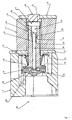
- the solenoid valve 10 has a valve housing 11 with associated housing cover plate 12.
- an electromagnetic linear actuator is mounted, consisting of an excitation coil 13, a magnetic yoke 14 and arranged in the interior of the exciter coil 13, longitudinally displaceable or vertically movable armature 15 is made.
- the armature 15 is at least partially surrounded by an anchor sleeve 16.
- the anchor sleeve 16 serves primarily as a guide for the armature 15. In a lower portion 17, the anchor sleeve 16 is bent outwardly, i. it extends in this section 17 perpendicular to a longitudinal axis of the armature 15th
- the armature 15 cooperates with a support member 18, which is associated with a valve closing body 19.
- a support member 18 which is associated with a valve closing body 19.
- the valve closing body 19 sits on a circumferential valve seat 20.
- the energizing coil 13 is de-energized, the valve closing body 19 is pressed onto the valve seat 20 by a closing spring 21 and held in the closed position of the solenoid valve 10 as shown in FIG.
- the closing spring 21 may e.g. be designed as a conical or coil spring.
- an air gap 24 is formed between an upper end 22 of the armature 15 and an upper end 23 of the armature sleeve 16.
- an air gap 24 is formed between an upper end 22 of the armature 15 and an upper end 23 of the armature sleeve 16.
- this force must act against a prevailing at the valve closing body 19 pressure difference and against the spring force of the closing spring 21. ever greater the pressure difference prevailing on the valve closing body, the greater must be the force required by the excitation coil for opening the solenoid valve, which causes the use of large excitation coils in solenoid valves according to the prior art.
- the solenoid valve of the present invention has in the armature 15 via a bore 25 which extends continuously in the longitudinal direction of the armature 15.
- a bore 25 which extends continuously in the longitudinal direction of the armature 15.
- an elongated, rod-shaped element 26 is arranged within the bore 25.
- the support member 18 facing the end 27 of the rod-shaped element 26 projects out of the bore 25.
- Figure 1 it can be seen that the rod-shaped element 26 protrudes with this end 27 through a bore of the support member 18 and is connected via a clamping element 28 with the support member 18.
- a spring element 29 is further positioned.
- the spring element 29 is supported at one end on a lower shoulder 30 of the bore 25 and at another end on a second end 31 of the rod-shaped element 26 from.
- Another shoulder 32 within the bore 25 positioned above the shoulder 30 forms a stop for the second end 31 of the rod-shaped member 26.
- the already mentioned closing spring 21 of the solenoid valve 10 is arranged between the anchor sleeve 16 and the valve closing body 19, wherein the closing spring 21 is supported with one end on the portion 17 of the anchor sleeve 16 and with another end on a lower portion 33 of the armature 15 , wherein this portion 33 is formed as a circumferential bead.
- the spring force provided by the spring element 29 is smaller than the spring force provided by the closing spring 21.
- the distance between the shoulder 32 of the bore 25 and the upper end 31 of the rod-shaped element 26 must be smaller than the total stroke range of the armature 15th
- the solenoid valve 10 of the present invention requires smaller and less expensive excitation coils to open a valve of a particular size than the prior art solenoid valves. As a result, the size is reduced. Also, the working noise of the solenoid valve are thereby positively influenced.
Landscapes
- Engineering & Computer Science (AREA)
- General Engineering & Computer Science (AREA)
- Mechanical Engineering (AREA)
- Magnetically Actuated Valves (AREA)
Claims (3)
- Vanne magnétique avec un corps de fermeture de vanne mobile (19) qui est associé à un élément de support (18), et un induit magnétique (15) qui coopère avec l'élément de support (18), avec les propriétés suivantes :l'induit magnétique (15) présente un perçage (25) qui s'étend d'un bout à l'autre dans son sens longitudinal ;dans le perçage (25) est disposé un élément en forme de tige (26) ;l'élément en forme de tige (26) dépasse du perçage (25) avec une première extrémité (27) tournée vers l'élément de support (18) et est relié à ce dernier au niveau de cette extrémité (27) tournée vers l'élément de support (18) ;le perçage (25) de l'induit magnétique (15) présente deux épaulements (30, 32) ;un élément élastique (29) est également disposé dans le perçage (25) ;l'élément élastique (29) est disposé entre un premier épaulement (30) et une seconde extrémité (31) de l'élément en forme de tige (26) et agit sur celle-ci ;avec une bobine d'excitation (13) pour produire, quand elle est activée, une force magnétique qui ouvre la vanne magnétique ;et avec un ressort de fermeture (21) pour presser le corps de fermeture de vanne (19) sur un siège de vanne (20) quand la bobine d'excitation (13) est hors tension,caractérisée en ce que le second épaulement (32) forme une butée pour la seconde extrémité (31) de l'élément en forme de tige (26), ce second épaulement (32) étant placé entre le premier épaulement (30) et la seconde extrémité (31) de l'élément en forme de tige (26), etla force élastique de l'élément élastique (29) est inférieure à celle du ressort de fermeture (21), et la distance entre le second épaulement (32) et la seconde extrémité élargie (31) de l'élément en forme de tige (26), dans un état non activé de la bobine d'excitation (13), est plus petite que la zone de course totale de l'induit magnétique (15).
- Vanne magnétique selon la revendication 1, caractérisée en ce que la première extrémité (27) de l'élément en forme de tige (26) traverse un perçage de l'élément de support (18) et est reliée à l'élément de support (18) par l'intermédiaire d'un élément de serrage (28).
- Vanne magnétique selon la revendication 1 ou 2, caractérisée en ce que l'induit magnétique (15) est entouré par une douille d'induit (16), le ressort de fermeture (21) étant disposé entre une partie (17) de la douille (16) et une partie (33) de l'induit (15) et agissant sur ces parties (17, 33), et la partie (33) de l'induit magnétique (15) étant par ailleurs posée sur l'élément de support (18).
Applications Claiming Priority (2)
| Application Number | Priority Date | Filing Date | Title |
|---|---|---|---|
| DE1998156488 DE19856488B4 (de) | 1998-12-08 | 1998-12-08 | Magnetventil |
| DE19856488 | 1998-12-08 |
Publications (3)
| Publication Number | Publication Date |
|---|---|
| EP1008792A2 EP1008792A2 (fr) | 2000-06-14 |
| EP1008792A3 EP1008792A3 (fr) | 2001-09-05 |
| EP1008792B1 true EP1008792B1 (fr) | 2007-04-18 |
Family
ID=7890313
Family Applications (1)
| Application Number | Title | Priority Date | Filing Date |
|---|---|---|---|
| EP99123883A Expired - Lifetime EP1008792B1 (fr) | 1998-12-08 | 1999-12-02 | Soupape magnétique |
Country Status (2)
| Country | Link |
|---|---|
| EP (1) | EP1008792B1 (fr) |
| DE (2) | DE19856488B4 (fr) |
Families Citing this family (2)
| Publication number | Priority date | Publication date | Assignee | Title |
|---|---|---|---|---|
| US6505812B1 (en) * | 2000-11-17 | 2003-01-14 | Mks Instruments, Inc. | Solenoid valve |
| DE102005014100B4 (de) * | 2004-07-15 | 2014-01-02 | Continental Teves Ag & Co. Ohg | Elektromagnetventil, insbesondere für schlupfgeregelte Kraftfahrzeugbremsanlagen |
Family Cites Families (9)
| Publication number | Priority date | Publication date | Assignee | Title |
|---|---|---|---|---|
| US4008876A (en) * | 1975-06-09 | 1977-02-22 | The Singer Company | Solenoid valve |
| DE4028447A1 (de) * | 1990-09-07 | 1992-03-12 | Teves Gmbh Alfred | Elektromagnetventil fuer hydraulische bremsanlagen mit schlupfregelung |
| US5209455A (en) * | 1990-11-19 | 1993-05-11 | Mitsubishi Materials Corporation | Valve and solenoid valve operated by very small force |
| DE4305987C1 (de) * | 1993-02-26 | 1993-11-25 | Honeywell Bv | Magnetventil mit Schmutzfalle |
| DE4306847A1 (de) * | 1993-03-01 | 1994-09-08 | Frank Pruefer | Elektromagnetisch betätigtes Ventil |
| DE19502671A1 (de) * | 1995-01-20 | 1996-08-01 | Mannesmann Ag | Elektromagnetantrieb, insbesondere für Elektromagnetventile als Stellglieder für Fluide |
| DE19504246A1 (de) * | 1995-02-09 | 1996-08-14 | Teves Gmbh Alfred | Elektromagnetventil mit Druckbegrenzungsfunktion, insbesondere für hydraulische Kraftfahrzeugbremsanlagen mit Schlupfregelung und/oder automatischem Bremseneingriff zur Fahrdynamikregelung |
| DE19510288A1 (de) * | 1995-03-22 | 1996-09-26 | Teves Gmbh Alfred | Elektromagnetventil mit Druckbegrenzungsfunktion, isnbesondere für hydraulische Kraftfahrzeug-Bremsanlageen mit Schlupfregelung und/oder automatischem Bremseneingriff zur Fahrdynamikregelung |
| DE19632552C1 (de) * | 1996-08-13 | 1997-12-11 | Honeywell Bv | Einstellvorrichtung für den magnetischen Widerstand eines Magnetkreises in einem Magnetventil |
-
1998
- 1998-12-08 DE DE1998156488 patent/DE19856488B4/de not_active Expired - Lifetime
-
1999
- 1999-12-02 DE DE59914299T patent/DE59914299D1/de not_active Expired - Lifetime
- 1999-12-02 EP EP99123883A patent/EP1008792B1/fr not_active Expired - Lifetime
Non-Patent Citations (1)
| Title |
|---|
| None * |
Also Published As
| Publication number | Publication date |
|---|---|
| EP1008792A2 (fr) | 2000-06-14 |
| DE19856488B4 (de) | 2004-02-26 |
| DE19856488A1 (de) | 2000-06-29 |
| DE59914299D1 (de) | 2007-05-31 |
| EP1008792A3 (fr) | 2001-09-05 |
Similar Documents
| Publication | Publication Date | Title |
|---|---|---|
| DE69517335T2 (de) | Elektromagnetisch gelenktes ventil mit gelenkter armatur | |
| EP1503926A1 (fr) | Soupape electromagnetique | |
| EP1232082A1 (fr) | Vanne electromagnetique | |
| DE102009012688B3 (de) | Ventil zum Einblasen von Gas | |
| DE4028447A1 (de) | Elektromagnetventil fuer hydraulische bremsanlagen mit schlupfregelung | |
| EP1811216B1 (fr) | Agencement d'actionnement destiné à l'actionnement d'un agencement d'aération | |
| DE19716856B4 (de) | Baueinheit für ein Hydraulikventil | |
| DE10016600A1 (de) | Elektromagnetventil | |
| DE10046939B4 (de) | Tauchankersystem mit Anschlagdämpfung | |
| DE10254342A1 (de) | Elektromagnetventil | |
| DE10064169A1 (de) | Elektromagnetventil | |
| DE10027171A1 (de) | Elektromagnetventil | |
| DE10311486A1 (de) | Elektromagnetventil | |
| EP1045785A1 (fr) | Soupape de reglage de pression, en particulier pour la regulation du fluide sous pression dans des installations de freinage hydrauliques a regulation anti-patinage | |
| WO2021063866A1 (fr) | Électrovanne, destinée en particulier à des systèmes de freinage de véhicules à moteur à régulation du glissement | |
| DE3317226A1 (de) | Betaetigungsmagnet | |
| EP2299458B1 (fr) | Électroaimant | |
| DE19856488B4 (de) | Magnetventil | |
| DE10216485B4 (de) | Verfahren zur Einstellung eines Elektromagnetventils | |
| EP1682802B1 (fr) | Soupape servant a commander le passage de fluides, comportant un element multifonctionnel | |
| EP1601869B1 (fr) | Soupape comportant un element ressort pour un injecteur de carburant | |
| EP4402027B1 (fr) | Vanne de controle de pression electromagnetique avec conduite d'air interne | |
| EP1068118A1 (fr) | Soupape d'arret avec fonction de limitation de pression, notamment pour systemes de freinage hydrauliques a antiblocage utilises dans des vehicules automobiles | |
| DE102021204203A1 (de) | Elektromagnetventil, insbesondere für schlupfgeregelte Kraftfahrzeugbremsanlagen | |
| DE10254341B4 (de) | Sitzventil |
Legal Events
| Date | Code | Title | Description |
|---|---|---|---|
| PUAI | Public reference made under article 153(3) epc to a published international application that has entered the european phase |
Free format text: ORIGINAL CODE: 0009012 |
|
| AK | Designated contracting states |
Kind code of ref document: A2 Designated state(s): AT BE CH CY DE DK ES FI FR GB GR IE IT LI LU MC NL PT SE |
|
| AX | Request for extension of the european patent |
Free format text: AL;LT;LV;MK;RO;SI |
|
| PUAL | Search report despatched |
Free format text: ORIGINAL CODE: 0009013 |
|
| AK | Designated contracting states |
Kind code of ref document: A3 Designated state(s): AT BE CH CY DE DK ES FI FR GB GR IE IT LI LU MC NL PT SE |
|
| AX | Request for extension of the european patent |
Free format text: AL;LT;LV;MK;RO;SI |
|
| 17P | Request for examination filed |
Effective date: 20011114 |
|
| AKX | Designation fees paid |
Free format text: DE FR GB IT NL |
|
| 17Q | First examination report despatched |
Effective date: 20040213 |
|
| GRAP | Despatch of communication of intention to grant a patent |
Free format text: ORIGINAL CODE: EPIDOSNIGR1 |
|
| GRAS | Grant fee paid |
Free format text: ORIGINAL CODE: EPIDOSNIGR3 |
|
| GRAA | (expected) grant |
Free format text: ORIGINAL CODE: 0009210 |
|
| AK | Designated contracting states |
Kind code of ref document: B1 Designated state(s): DE FR GB IT NL |
|
| GBT | Gb: translation of ep patent filed (gb section 77(6)(a)/1977) |
Effective date: 20070502 |
|
| REF | Corresponds to: |
Ref document number: 59914299 Country of ref document: DE Date of ref document: 20070531 Kind code of ref document: P |
|
| PLBE | No opposition filed within time limit |
Free format text: ORIGINAL CODE: 0009261 |
|
| STAA | Information on the status of an ep patent application or granted ep patent |
Free format text: STATUS: NO OPPOSITION FILED WITHIN TIME LIMIT |
|
| 26N | No opposition filed |
Effective date: 20080121 |
|
| REG | Reference to a national code |
Ref country code: GB Ref legal event code: 732E |
|
| NLS | Nl: assignments of ep-patents |
Owner name: HONEYWELL TECHNOLOGIES SARL Effective date: 20080618 |
|
| REG | Reference to a national code |
Ref country code: FR Ref legal event code: TP |
|
| PGFP | Annual fee paid to national office [announced via postgrant information from national office to epo] |
Ref country code: GB Payment date: 20141124 Year of fee payment: 16 |
|
| PGFP | Annual fee paid to national office [announced via postgrant information from national office to epo] |
Ref country code: NL Payment date: 20141209 Year of fee payment: 16 |
|
| REG | Reference to a national code |
Ref country code: FR Ref legal event code: PLFP Year of fee payment: 17 |
|
| GBPC | Gb: european patent ceased through non-payment of renewal fee |
Effective date: 20151202 |
|
| REG | Reference to a national code |
Ref country code: NL Ref legal event code: MM Effective date: 20160101 |
|
| PG25 | Lapsed in a contracting state [announced via postgrant information from national office to epo] |
Ref country code: GB Free format text: LAPSE BECAUSE OF NON-PAYMENT OF DUE FEES Effective date: 20151202 Ref country code: NL Free format text: LAPSE BECAUSE OF NON-PAYMENT OF DUE FEES Effective date: 20160101 |
|
| REG | Reference to a national code |
Ref country code: FR Ref legal event code: PLFP Year of fee payment: 18 |
|
| REG | Reference to a national code |
Ref country code: FR Ref legal event code: PLFP Year of fee payment: 19 |
|
| PGFP | Annual fee paid to national office [announced via postgrant information from national office to epo] |
Ref country code: DE Payment date: 20180228 Year of fee payment: 19 |
|
| PGFP | Annual fee paid to national office [announced via postgrant information from national office to epo] |
Ref country code: IT Payment date: 20171220 Year of fee payment: 19 |
|
| PGFP | Annual fee paid to national office [announced via postgrant information from national office to epo] |
Ref country code: FR Payment date: 20181231 Year of fee payment: 20 |
|
| REG | Reference to a national code |
Ref country code: DE Ref legal event code: R119 Ref document number: 59914299 Country of ref document: DE |
|
| PG25 | Lapsed in a contracting state [announced via postgrant information from national office to epo] |
Ref country code: DE Free format text: LAPSE BECAUSE OF NON-PAYMENT OF DUE FEES Effective date: 20190702 Ref country code: IT Free format text: LAPSE BECAUSE OF NON-PAYMENT OF DUE FEES Effective date: 20181202 |