EP1008980A1 - Procede de correction d'image dynamique et circuit de correction d'image dynamique pour ecran - Google Patents
Procede de correction d'image dynamique et circuit de correction d'image dynamique pour ecran Download PDFInfo
- Publication number
- EP1008980A1 EP1008980A1 EP98911157A EP98911157A EP1008980A1 EP 1008980 A1 EP1008980 A1 EP 1008980A1 EP 98911157 A EP98911157 A EP 98911157A EP 98911157 A EP98911157 A EP 98911157A EP 1008980 A1 EP1008980 A1 EP 1008980A1
- Authority
- EP
- European Patent Office
- Prior art keywords
- dynamic image
- subfields
- video signal
- image correction
- frame
- Prior art date
- Legal status (The legal status is an assumption and is not a legal conclusion. Google has not performed a legal analysis and makes no representation as to the accuracy of the status listed.)
- Withdrawn
Links
Images


Classifications
-
- G—PHYSICS
- G09—EDUCATION; CRYPTOGRAPHY; DISPLAY; ADVERTISING; SEALS
- G09G—ARRANGEMENTS OR CIRCUITS FOR CONTROL OF INDICATING DEVICES USING STATIC MEANS TO PRESENT VARIABLE INFORMATION
- G09G3/00—Control arrangements or circuits, of interest only in connection with visual indicators other than cathode-ray tubes
- G09G3/20—Control arrangements or circuits, of interest only in connection with visual indicators other than cathode-ray tubes for presentation of an assembly of a number of characters, e.g. a page, by composing the assembly by combination of individual elements arranged in a matrix no fixed position being assigned to or needed to be assigned to the individual characters or partial characters
-
- G—PHYSICS
- G09—EDUCATION; CRYPTOGRAPHY; DISPLAY; ADVERTISING; SEALS
- G09G—ARRANGEMENTS OR CIRCUITS FOR CONTROL OF INDICATING DEVICES USING STATIC MEANS TO PRESENT VARIABLE INFORMATION
- G09G3/00—Control arrangements or circuits, of interest only in connection with visual indicators other than cathode-ray tubes
- G09G3/20—Control arrangements or circuits, of interest only in connection with visual indicators other than cathode-ray tubes for presentation of an assembly of a number of characters, e.g. a page, by composing the assembly by combination of individual elements arranged in a matrix no fixed position being assigned to or needed to be assigned to the individual characters or partial characters
- G09G3/2007—Display of intermediate tones
- G09G3/2018—Display of intermediate tones by time modulation using two or more time intervals
- G09G3/2022—Display of intermediate tones by time modulation using two or more time intervals using sub-frames
-
- G—PHYSICS
- G09—EDUCATION; CRYPTOGRAPHY; DISPLAY; ADVERTISING; SEALS
- G09G—ARRANGEMENTS OR CIRCUITS FOR CONTROL OF INDICATING DEVICES USING STATIC MEANS TO PRESENT VARIABLE INFORMATION
- G09G2320/00—Control of display operating conditions
- G09G2320/02—Improving the quality of display appearance
- G09G2320/0261—Improving the quality of display appearance in the context of movement of objects on the screen or movement of the observer relative to the screen
-
- G—PHYSICS
- G09—EDUCATION; CRYPTOGRAPHY; DISPLAY; ADVERTISING; SEALS
- G09G—ARRANGEMENTS OR CIRCUITS FOR CONTROL OF INDICATING DEVICES USING STATIC MEANS TO PRESENT VARIABLE INFORMATION
- G09G2320/00—Control of display operating conditions
- G09G2320/02—Improving the quality of display appearance
- G09G2320/0266—Reduction of sub-frame artefacts
-
- G—PHYSICS
- G09—EDUCATION; CRYPTOGRAPHY; DISPLAY; ADVERTISING; SEALS
- G09G—ARRANGEMENTS OR CIRCUITS FOR CONTROL OF INDICATING DEVICES USING STATIC MEANS TO PRESENT VARIABLE INFORMATION
- G09G2320/00—Control of display operating conditions
- G09G2320/10—Special adaptations of display systems for operation with variable images
- G09G2320/106—Determination of movement vectors or equivalent parameters within the image
-
- G—PHYSICS
- G09—EDUCATION; CRYPTOGRAPHY; DISPLAY; ADVERTISING; SEALS
- G09G—ARRANGEMENTS OR CIRCUITS FOR CONTROL OF INDICATING DEVICES USING STATIC MEANS TO PRESENT VARIABLE INFORMATION
- G09G3/00—Control arrangements or circuits, of interest only in connection with visual indicators other than cathode-ray tubes
- G09G3/20—Control arrangements or circuits, of interest only in connection with visual indicators other than cathode-ray tubes for presentation of an assembly of a number of characters, e.g. a page, by composing the assembly by combination of individual elements arranged in a matrix no fixed position being assigned to or needed to be assigned to the individual characters or partial characters
- G09G3/22—Control arrangements or circuits, of interest only in connection with visual indicators other than cathode-ray tubes for presentation of an assembly of a number of characters, e.g. a page, by composing the assembly by combination of individual elements arranged in a matrix no fixed position being assigned to or needed to be assigned to the individual characters or partial characters using controlled light sources
- G09G3/28—Control arrangements or circuits, of interest only in connection with visual indicators other than cathode-ray tubes for presentation of an assembly of a number of characters, e.g. a page, by composing the assembly by combination of individual elements arranged in a matrix no fixed position being assigned to or needed to be assigned to the individual characters or partial characters using controlled light sources using luminous gas-discharge panels, e.g. plasma panels
- G09G3/2803—Display of gradations
Definitions
- the present invention relates to a dynamic image correction method and dynamic image correction circuit of display device, wherein one frame is divided into a plurality of subfields (or subframes) on time-sharing basis and the subfields are made to emit light according to luminance levels of input signals for producing multi-gradation image.
- PDP Plasma Display Panel
- LCD Liquid Crystal Display
- the PDP can be divided into two types, namely, AC-type and DC-types differing in basic characteristic.
- AC-type PDP sufficient characteristics can be obtained as to luminance and service life, while availability of only up to 64 gradations has been reported on trial manufacture basis, but a method for enabling 256 gradations by address display separation method in the future has already been proposed.
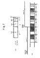
- one frame comprises 8 subfields SF1, SF2, SF3, SF4, SF5, SF6, SF7 and SF8 having luminance ratios of 1, 2, 4, 8, 16, 32, 64, 128, and display of 256 gradations is available by combining the luminances of 8 images.
- each subfield comprises an address period for writing the data for 1 image and a sustain period for determining the luminance level of the subfield.
- initial wall charge is formed simultaneously for each of the pixels of all the images, and then sustain pulse is given to all the images for display.
- the brightness of the subfield is proportional to the number of the sustain pulse and set to a predetermined luminance.
- the 256-gradation display is made available in this way.
- input video signal (original signal) is a discrete signal, which is sampled for each frame (or field), thereby giving rise to a problem such as degradation of picture quality resulting from the visual disagreement in the direction of the movement of the dynamic image and the presence of the level not in accordance with the original signal.
- the dynamic image correction according to the prior art has been made by applying only one predetermined dynamic image correction method on the basis of the input video signal, regardless of the rate of the movement of block during one frame or during a plurality of frames.
- one block means an area of image formed with one or a plurality of picture elements, e.g., 2x2 picture elements.
- the dynamic image is corrected by using only one same dynamic image correction method regardless of rapid moving part of dynamic image (hereinafter referred to as “rapid moving dynamic image part”) and slow moving part of dynamic image (hereinafter referred to as “slow moving dynamic image part”), thereby causing a problem such that, when the dynamic image correction method is adapted for the rapid moving dynamic image part, correction for the slow moving dynamic image part becomes insufficient and vice versa.
- rapid moving dynamic image part rapid moving part of dynamic image
- slow moving dynamic image part slow moving part of dynamic image
- the present invention devised, in consideration of the problem of the prior art, for the display device having one frame divided into a plurality of subfields which emit light according to luminance level of input video signal for displaying multi-gradation image, is designed to provide a dynamic image correction method and a dynamic image correction circuit capable of effecting optimum dynamic image correction for both the rapid moving dynamic image part and the slow moving dynamic image part.
- the moving vector of the block during one frame or the blocks during a plurality of frames is or are detected, and, depending on whether the value of detected moving vector is larger than the preset value S or not, either a signal obtained by correcting input video signal by the rapid moving dynamic image correction means or a signal obtained by correcting input video signal by the slow moving dynamic image correction means is selectively output to the display device.
- the input video signal is corrected by the rapid moving dynamic image correction means for output to the display device, while when the value of the detected moving vector is smaller than the preset value S, the input video signal is corrected by the slow moving dynamic image correction means for output to the display device, whereby an optimum dynamic image correction can be accomplished for both the rapid moving dynamic image part and slow moving dynamic image part to be displayed on the display device.
- the rapid moving dynamic image correction means not only selects the light emitted from corresponding subfields among n number of subfields, SFn, SF(n-1), ... SF1, which constitute one frame, according to the luminance level of input video signal but also corrects the display positions of the n number of subfields SFn ⁇ SF1 in each frame of input video signal depending on the value of detected moving vector, while the slow moving dynamic image correction means selects the light emitted from the subfields SF(n-1), ...
- SF1 and SF1a being adjacent to SF1 and having a luminance ratio equivalent to that of SF1, which constitute one frame, only when the luminance levels of input video signal has varied from 2 (n-1) -1 to 2 (n-1) , but selects the light emitted from the corresponding subfields among n number of subfields, SFn ⁇ SF1 not including the subfield SF1a with respect to the luminance levels other than those described previously. Therefore, when the value of detected moving vector is larger than the preset value S, the display positions of the subfields SFn ⁇ SF1 can be made to match with the visual path of the eye of a person watching the dynamic image.
- the dynamic image correction circuit of present invention incorporated into the display device wherein one frame is divided into a plurality of subfields on time-sharing basis for emitting light from the subfields according to luminance level of input video signal to display multi-gradation image, comprises a moving vector detector for detecting the moving vector of the block during one frame or moving vector of the block during a plurality of frames, a rapid moving dynamic image corrector for correcting for output an input video signal by using a proper dynamic image correction means when the value of the moving vector detected by the moving vector detector is larger than preset value S, a slow moving dynamic image corrector for correcting for output an input video signal by using a proper dynamic image correction means and a discriminating selector for discriminating an output signal from the rapid moving dynamic image corrector from an output signal from the slow moving dynamic image corrector for output to the display device depending on whether the value of the moving vector detected by the moving vector detector is larger or smaller than the preset value S.
- the discriminating selector outputs the input video signal corrected by the rapid moving dynamic image corrector to the display device when the value of detected moving vector is larger than the preset value S and outputs the input video signal corrected by the slow moving dynamic image corrector to the display device when the value of detected moving vector is smaller than the preset value S, so that an optimum dynamic image correction can be accomplished for both the rapid moving dynamic image part and the slow moving dynamic image part to be displayed on the display device.
- the display positions of the subfields, SFn ⁇ SF1 can be made to match with the visual path of the eye of a person watching the dynamic image by using the rapid moving dynamic image corrector.
- Fig.2 shows an embodiment of the dynamic image correction circuit for carrying out the dynamic image correction method for the display device according to the present invention.
- reference numeral 10 denotes the moving vector detector, which detects and outputs the moving vector (direction and amount of movement) of the block (e.g., 2x2 picture elements) during one frame or the blocks during a plurality of frames on the basis of the video signal input to input terminal 12. For instance, on the bases of the video signals of the present frame and preceding frame, the moving vector of the block to be corrected for the image of the present frame of the PDP is detected and output by the moving vector detector.
- the moving vector detector which detects and outputs the moving vector (direction and amount of movement) of the block (e.g., 2x2 picture elements) during one frame or the blocks during a plurality of frames on the basis of the video signal input to input terminal 12. For instance, on the bases of the video signals of the present frame and preceding frame, the moving vector of the block to be corrected for the image of the present frame of the PDP is detected and output by the moving vector detector.
- Reference numeral 14 denotes the rapid moving dynamic image corrector, which corrects the video signal input to the input terminal 12 by proper dynamic image correction means and outputs the corrected video signal, when the value of the moving vector detected by the moving vector detector 10 is larger (e.g., equal to or larger than S) than the preset value S (e.g., 2 dots/ frame).
- Reference numeral 16 denotes the slow moving dynamic image corrector, which corrects the video signal input to the input terminal 12 by proper dynamic image correction means and outputs the corrected video signal, when the value of the moving vector detected by the moving vector detector 10 is smaller than the preset value S (e.g., S or less).
- S preset value
- Reference numeral 18 denotes the discriminating selector, which selectively outputs the signal output from the rapid moving dynamic image corrector 14 or the signal output from the slow moving dynamic image corrector 16 to output terminal 20, depending on whether the value of the moving vector detected by the moving vector detector 10 is larger or smaller than the preset value S.
- the rapid moving dynamic image corrector 14 has a construction, for example, substantially the same as that of corresponding rapid moving dynamic image corrector for the dynamic image correction method and the dynamic image corrector according to (Japanese Patent Application Publication No.H7-317508 (317508/1995)), the application therefor having already been filed by the present applicant.
- the rapid moving dynamic image corrector 14 comprising a data conversion circuit for converting input n-bit video signal into display data of subfields SFn ⁇ SF1 and a ROM (read-only memory) for outputting the data representing the corrected display positions of the subfields SFn ⁇ SF1 with address represented by the detected moving vector, not only selects the light emitted from the corresponding subfields among the n number of subfields SFn ⁇ SF1 according to the luminance level of video signal input to the input terminal 12 but also outputs the signal corrected as to the display positions of subfields SFn ⁇ SF1 of each frame of input video signal according to the value of the moving vector detected by the moving vector detector 10.
- the slow moving dynamic image corrector 16 has a construction, for example, substantially the same as that of the corresponding slow moving dynamic image corrector incorporated into the display device drive method according to Japanese Patent Application Publication No.H7-108191(108191/1995) which has been filed by the present inventor. That is, the slow moving dynamic image corrector 16 is designed to select the light emitted from n number of subfields, SF(n-1), SF(n-2), ... SF1 and adjacent SF1a, composing one frame and having luminance ratios 2 (n-1) , 2 (n-2) , ...
- the rapid moving dynamic image corrector is explained with reference to the case where one frame is composed of 4 subfields SF4 ⁇ SF1
- the slow moving dynamic image corrector is explained with reference to the case where one frame is composed of 4 subfields SF4 ⁇ SF1 and a subfield SF1a adjacent to the subfield SF1, 5 subfields in total (i.e., 5 bits), but the present invention is not limited to this.
- the rapid moving dynamic image corrector is applicable to the case where one frame is composed of n number (n is any integer not less than 2) of subfields SFn ⁇ SF1
- the slow moving dynamic image corrector is applicable to the case where one frame is composed of n 1 number of subfields, i.e., n number of subfields SFn ⁇ SF1 plus one subfield SF1a in total, (case where the image is of gradation of 2 n ).
- the latter can also be applied to the case where the subfield SF1a is omitted.
- the signal output from the slow moving dynamic image corrector 16, described previously in (3) becomes a signal to induce the emission of light from the subfields SF4, SF3, SF2, SF1 and SF1a only when the luminance level has varied to 16 from 15. Therefore, at the point at which the luminance level varies from 15 to 16, bit value varies from 011110 to 01111, and the emission of light will not continue, so that there is no substantial variation of luminance level thereby preventing degradation of picture quality.
- the rapid moving dynamic image corrector is designed not only to select the emission of light from corresponding subfields among n number of subfields SFn - SF1 according to the luminance level of input video signal but also corrects the display positions of the n number of subfields of each frame of input video signal according to the value of the moving vector, but the present invention is not limited to this embodiment, and thus it is sufficient for the rapid moving dynamic image corrector to be any one which is capable of correcting input video signal for output by using proper correction means when the value of the moving vector detected by the moving vector detector is larger than the preset value S.
- the slow moving dynamic image corrector is designed to select the light emitted from subfields SF(n-1), ... SF1 and SF1a only when the luminance level of input video signal has varied from 2 (n-1) -1 to 2 (n-1) , and select the light emitted from corresponding subfields among n number of subfields SFn ⁇ SF1 not including subfield SF1a with respect to the luminance level other than that described previously, but the present invention is not limited to this embodiment, and thus it is sufficient for the slow moving dynamic image corrector to be any one which is capable of correcting for output the video signal by using proper dynamic image correction means when the value of the moving vector detected by the moving vector detector is smaller than the preset value S.
- the present invention is designed to provide an optimum dynamic image correction for both the rapid moving part and slow moving part of dynamic image when applied to a display device (e.g., display devices using PDP or LCD), wherein one frame is divided into a plurality of subfields on time-sharing basis, and the image of multigradation is produced by having subfields emit light according to the luminance level of input video signal.
- a display device e.g., display devices using PDP or LCD
Landscapes
- Engineering & Computer Science (AREA)
- Physics & Mathematics (AREA)
- Computer Hardware Design (AREA)
- General Physics & Mathematics (AREA)
- Theoretical Computer Science (AREA)
- Control Of Indicators Other Than Cathode Ray Tubes (AREA)
- Control Of Gas Discharge Display Tubes (AREA)
- Liquid Crystal Display Device Control (AREA)
- Television Systems (AREA)
Applications Claiming Priority (3)
| Application Number | Priority Date | Filing Date | Title |
|---|---|---|---|
| JP10827997 | 1997-04-10 | ||
| JP10827997A JP3758294B2 (ja) | 1997-04-10 | 1997-04-10 | ディスプレイ装置の動画補正方法及び動画補正回路 |
| PCT/JP1998/001503 WO1998045831A1 (fr) | 1997-04-10 | 1998-04-01 | Procede de correction d'image dynamique et circuit de correction d'image dynamique pour ecran |
Publications (2)
| Publication Number | Publication Date |
|---|---|
| EP1008980A1 true EP1008980A1 (fr) | 2000-06-14 |
| EP1008980A4 EP1008980A4 (fr) | 2000-09-06 |
Family
ID=14480626
Family Applications (1)
| Application Number | Title | Priority Date | Filing Date |
|---|---|---|---|
| EP98911157A Withdrawn EP1008980A4 (fr) | 1997-04-10 | 1998-04-01 | Procede de correction d'image dynamique et circuit de correction d'image dynamique pour ecran |
Country Status (9)
| Country | Link |
|---|---|
| US (1) | US6335735B1 (fr) |
| EP (1) | EP1008980A4 (fr) |
| JP (1) | JP3758294B2 (fr) |
| KR (1) | KR100485610B1 (fr) |
| AU (1) | AU738827B2 (fr) |
| CA (1) | CA2286354C (fr) |
| RU (1) | RU2198434C2 (fr) |
| TW (1) | TW373159B (fr) |
| WO (1) | WO1998045831A1 (fr) |
Cited By (5)
| Publication number | Priority date | Publication date | Assignee | Title |
|---|---|---|---|---|
| WO1999049448A2 (fr) | 1998-03-23 | 1999-09-30 | Koninklijke Philips Electronics N.V. | Commande d'affichage |
| EP1374214A2 (fr) * | 2001-02-21 | 2004-01-02 | Koninklijke Philips Electronics N.V. | Unite de visualisation d'images et procede d'affichage de pixels et dispositif de visualisation comprenant une telle unite de visualisation d'images |
| US7102599B2 (en) * | 2001-09-07 | 2006-09-05 | Pioneer Corporation | Identification method for generated position of dynamic false contour, processing method for image signal, and processing apparatus for image signal |
| US20090273707A1 (en) * | 2008-05-01 | 2009-11-05 | Canon Kabushiki Kaisha | Frame rate conversion apparatus, frame rate conversion method, and computer-readable storage medium |
| US8842137B2 (en) | 2008-05-01 | 2014-09-23 | Canon Kabushiki Kaisha | Frame rate conversion apparatus, frame rate conversion method, and computer-readable storage medium |
Families Citing this family (20)
| Publication number | Priority date | Publication date | Assignee | Title |
|---|---|---|---|---|
| CN1160681C (zh) * | 1999-04-12 | 2004-08-04 | 松下电器产业株式会社 | 图象显示装置 |
| WO2000067248A1 (fr) * | 1999-04-28 | 2000-11-09 | Matsushita Electric Industrial Co., Ltd. | Afficheur |
| WO2001039488A2 (fr) * | 1999-11-26 | 2001-05-31 | Koninklijke Philips Electronics N.V. | Procede de traitement d'images et dispositif a cet effet |
| JP4240743B2 (ja) * | 2000-03-29 | 2009-03-18 | ソニー株式会社 | 液晶表示装置及びその駆動方法 |
| JP2004519708A (ja) * | 2001-02-23 | 2004-07-02 | コーニンクレッカ フィリップス エレクトロニクス エヌ ヴィ | サブフィールドで画像を表示する方法及びユニット |
| JP3660610B2 (ja) * | 2001-07-10 | 2005-06-15 | 株式会社東芝 | 画像表示方法 |
| US6753876B2 (en) * | 2001-12-21 | 2004-06-22 | General Electric Company | Method for high dynamic range image construction based on multiple images with multiple illumination intensities |
| JP4253158B2 (ja) * | 2002-03-29 | 2009-04-08 | 富士フイルム株式会社 | 画像処理装置、プログラム、画像処理方法、及び動画像の生産方法 |
| KR100570681B1 (ko) * | 2003-10-31 | 2006-04-12 | 삼성에스디아이 주식회사 | 플라즈마 디스플레이 패널의 화상 표시 방법 및 그 장치 |
| KR100726142B1 (ko) * | 2004-02-18 | 2007-06-13 | 마쯔시다덴기산교 가부시키가이샤 | 화상 보정 방법 및 화상 보정 장치 |
| JP2005311860A (ja) * | 2004-04-23 | 2005-11-04 | Toshiba Corp | 映像信号処理装置及び表示装置及び受信装置及び表示方法 |
| US8179400B2 (en) * | 2005-12-13 | 2012-05-15 | Koninklijke Philips Electronics N.V. | Motion adaptive ambient lighting |
| CN101449312B (zh) * | 2006-05-23 | 2012-06-20 | 松下电器产业株式会社 | 图像显示装置、图像显示方法、等离子体显示屏装置以及集成电路 |
| TW200834537A (en) * | 2006-12-18 | 2008-08-16 | Sony Corp | Dynamic image signal processing device |
| JP5141043B2 (ja) * | 2007-02-27 | 2013-02-13 | 株式会社日立製作所 | 画像表示装置および画像表示方法 |
| JP2008261984A (ja) * | 2007-04-11 | 2008-10-30 | Hitachi Ltd | 画像処理方法及びこれを用いた画像表示装置 |
| RU2346331C1 (ru) * | 2007-06-04 | 2009-02-10 | Закрытое акционерное общество Промышленная группа "Метран" | Способ автоматического определения правильности отображения информации на жидкокристаллическом индикаторе |
| US8345038B2 (en) | 2007-10-30 | 2013-01-01 | Sharp Laboratories Of America, Inc. | Methods and systems for backlight modulation and brightness preservation |
| WO2010089956A1 (fr) * | 2009-02-04 | 2010-08-12 | パナソニック株式会社 | Appareil de traitement d'image et appareil d'affichage d'image |
| WO2011086877A1 (fr) * | 2010-01-13 | 2011-07-21 | パナソニック株式会社 | Dispositif de traitement vidéo et dispositif d'affichage vidéo |
Family Cites Families (21)
| Publication number | Priority date | Publication date | Assignee | Title |
|---|---|---|---|---|
| JPS6334593A (ja) * | 1986-07-30 | 1988-02-15 | ホシデン株式会社 | 多階調表示方法 |
| US5543819A (en) * | 1988-07-21 | 1996-08-06 | Proxima Corporation | High resolution display system and method of using same |
| US5166788A (en) * | 1990-06-29 | 1992-11-24 | Samsung Electronics Co., Ltd. | Motion signal processor |
| RU2030840C1 (ru) * | 1990-10-10 | 1995-03-10 | Владимир Ефимович Теслер | Способ компенсации искажений сигнала движущегося объекта и устройство для его осуществления |
| JP3259253B2 (ja) * | 1990-11-28 | 2002-02-25 | 富士通株式会社 | フラット型表示装置の階調駆動方法及び階調駆動装置 |
| EP1231590A3 (fr) * | 1991-12-20 | 2003-08-06 | Fujitsu Limited | Circuit de commande d'un panneau d'affichage |
| JPH06351000A (ja) * | 1993-06-07 | 1994-12-22 | Matsushita Electric Ind Co Ltd | 画像信号符号化装置と画像信号復号装置 |
| US5452024A (en) | 1993-11-01 | 1995-09-19 | Texas Instruments Incorporated | DMD display system |
| CA2138834C (fr) * | 1994-01-07 | 2004-10-19 | Robert J. Gove | Systeme d'affichage video a desentrelacement numerique |
| KR970009492B1 (ko) * | 1994-05-19 | 1997-06-13 | 삼성전자 주식회사 | 수상관의 화상보정회로 및 그 방법 |
| JP3158904B2 (ja) * | 1994-10-19 | 2001-04-23 | 株式会社富士通ゼネラル | ディスプレイパネルの映像表示方法 |
| JP3312529B2 (ja) * | 1995-04-07 | 2002-08-12 | 株式会社富士通ゼネラル | ディスプレイ装置の駆動方法 |
| WO1996031865A1 (fr) * | 1995-04-07 | 1996-10-10 | Fujitsu General Limited | Procede de commande de dispositif d'affichage et circuit correspondant |
| US5900886A (en) * | 1995-05-26 | 1999-05-04 | National Semiconductor Corporation | Display controller capable of accessing an external memory for gray scale modulation data |
| JPH0981074A (ja) * | 1995-09-19 | 1997-03-28 | Fujitsu Ltd | ディスプレイ装置及びディスプレイユニット及びディスプレイ信号生成装置 |
| JPH09138666A (ja) * | 1995-11-10 | 1997-05-27 | Fujitsu General Ltd | 表示装置の動画補正方法及び動画補正装置 |
| US6127991A (en) * | 1996-11-12 | 2000-10-03 | Sanyo Electric Co., Ltd. | Method of driving flat panel display apparatus for multi-gradation display |
| US6064359A (en) * | 1997-07-09 | 2000-05-16 | Seiko Epson Corporation | Frame rate modulation for liquid crystal display (LCD) |
| US6175355B1 (en) * | 1997-07-11 | 2001-01-16 | National Semiconductor Corporation | Dispersion-based technique for modulating pixels of a digital display panel |
| DE69839542D1 (de) * | 1997-08-07 | 2008-07-10 | Hitachi Ltd | Farbbildanzeigeeinrichtung und -verfahren |
| JP2000020004A (ja) * | 1998-06-26 | 2000-01-21 | Mitsubishi Electric Corp | 画像表示装置 |
-
1997
- 1997-04-10 JP JP10827997A patent/JP3758294B2/ja not_active Expired - Fee Related
-
1998
- 1998-04-01 WO PCT/JP1998/001503 patent/WO1998045831A1/fr not_active Ceased
- 1998-04-01 KR KR10-1999-7009258A patent/KR100485610B1/ko not_active Expired - Fee Related
- 1998-04-01 AU AU65216/98A patent/AU738827B2/en not_active Ceased
- 1998-04-01 RU RU99123371/09A patent/RU2198434C2/ru not_active IP Right Cessation
- 1998-04-01 CA CA002286354A patent/CA2286354C/fr not_active Expired - Fee Related
- 1998-04-01 EP EP98911157A patent/EP1008980A4/fr not_active Withdrawn
- 1998-04-01 US US09/402,562 patent/US6335735B1/en not_active Expired - Lifetime
- 1998-04-03 TW TW087105084A patent/TW373159B/zh not_active IP Right Cessation
Cited By (7)
| Publication number | Priority date | Publication date | Assignee | Title |
|---|---|---|---|---|
| WO1999049448A2 (fr) | 1998-03-23 | 1999-09-30 | Koninklijke Philips Electronics N.V. | Commande d'affichage |
| EP0983584A2 (fr) * | 1998-03-23 | 2000-03-08 | Koninklijke Philips Electronics N.V. | Commande d'affichage |
| EP1374214A2 (fr) * | 2001-02-21 | 2004-01-02 | Koninklijke Philips Electronics N.V. | Unite de visualisation d'images et procede d'affichage de pixels et dispositif de visualisation comprenant une telle unite de visualisation d'images |
| US7102599B2 (en) * | 2001-09-07 | 2006-09-05 | Pioneer Corporation | Identification method for generated position of dynamic false contour, processing method for image signal, and processing apparatus for image signal |
| US20090273707A1 (en) * | 2008-05-01 | 2009-11-05 | Canon Kabushiki Kaisha | Frame rate conversion apparatus, frame rate conversion method, and computer-readable storage medium |
| EP2124430A1 (fr) * | 2008-05-01 | 2009-11-25 | Canon Kabushiki Kaisha | Appareil de conversion de fréquence d'image, procédé de conversion de fréquence d'image, et support de stockage lisible sur ordinateur |
| US8842137B2 (en) | 2008-05-01 | 2014-09-23 | Canon Kabushiki Kaisha | Frame rate conversion apparatus, frame rate conversion method, and computer-readable storage medium |
Also Published As
| Publication number | Publication date |
|---|---|
| KR100485610B1 (ko) | 2005-04-27 |
| RU2198434C2 (ru) | 2003-02-10 |
| CA2286354C (fr) | 2005-01-11 |
| AU6521698A (en) | 1998-10-30 |
| TW373159B (en) | 1999-11-01 |
| AU738827B2 (en) | 2001-09-27 |
| WO1998045831A1 (fr) | 1998-10-15 |
| JP3758294B2 (ja) | 2006-03-22 |
| EP1008980A4 (fr) | 2000-09-06 |
| KR20010006179A (ko) | 2001-01-26 |
| JPH10282930A (ja) | 1998-10-23 |
| US6335735B1 (en) | 2002-01-01 |
| CA2286354A1 (fr) | 1998-10-15 |
Similar Documents
| Publication | Publication Date | Title |
|---|---|---|
| AU738827B2 (en) | Dynamic image correction method and dynamic image correction circuit for display Device | |
| US6965358B1 (en) | Apparatus and method for making a gray scale display with subframes | |
| EP1032931B1 (fr) | Controleur d'impulsion de commande d'ecran plasma destine a empecher une fluctuation en sous-trame | |
| JPH0934399A (ja) | 中間調表示方法 | |
| KR19980703292A (ko) | 디스플레이장치의 구동방법 및 그 회로 | |
| KR100438604B1 (ko) | 플라즈마 디스플레이 패널의 계조표시 처리방법 | |
| JP2005321775A (ja) | ディスプレー装置 | |
| JPH09138666A (ja) | 表示装置の動画補正方法及び動画補正装置 | |
| US20070222712A1 (en) | Image Display Apparatus and Method of Driving the Same | |
| JP4069103B2 (ja) | 画像表示装置およびその駆動方法 | |
| JP3493864B2 (ja) | 表示装置の駆動方法及び駆動回路 | |
| JP3521591B2 (ja) | ディスプレイ装置の誤差拡散処理装置 | |
| EP1583063A1 (fr) | Unite d'afficheur et procede d'affichage | |
| JP3624600B2 (ja) | 表示装置の動画補正回路 | |
| EP1732055B1 (fr) | Dispositif d'affichage | |
| JP4158950B2 (ja) | ディスプレイ装置の動画補正回路 | |
| JP3449083B2 (ja) | 表示装置の駆動方法及び駆動回路 | |
| JP3521592B2 (ja) | ディスプレイ装置の誤差拡散処理装置 | |
| JPH10161587A (ja) | 表示装置の動画補正方法及び動画補正回路 | |
| JP2005308949A (ja) | 画像表示方法および画像表示装置 | |
| JPH10274962A (ja) | ディスプレイ装置の動画補正回路 | |
| JP2002268604A (ja) | プラズマディスプレイパネルの階調表示処理装置及び処理方法 | |
| JPH10161586A (ja) | 表示装置の駆動方法及び駆動回路 | |
| JP2004258069A (ja) | 画像表示装置 | |
| JPH10161588A (ja) | 表示装置の駆動方法及び駆動回路 |
Legal Events
| Date | Code | Title | Description |
|---|---|---|---|
| PUAI | Public reference made under article 153(3) epc to a published international application that has entered the european phase |
Free format text: ORIGINAL CODE: 0009012 |
|
| 17P | Request for examination filed |
Effective date: 19991105 |
|
| AK | Designated contracting states |
Kind code of ref document: A1 Designated state(s): DE ES FR GB IT NL |
|
| A4 | Supplementary search report drawn up and despatched |
Effective date: 20000726 |
|
| AK | Designated contracting states |
Kind code of ref document: A4 Designated state(s): DE ES FR GB IT NL |
|
| RIC1 | Information provided on ipc code assigned before grant |
Free format text: 7G 09G 3/20 A, 7G 09G 3/28 B, 7H 04N 5/14 B |
|
| RAP1 | Party data changed (applicant data changed or rights of an application transferred) |
Owner name: CANON KABUSHIKI KAISHA |
|
| 17Q | First examination report despatched |
Effective date: 20081006 |
|
| STAA | Information on the status of an ep patent application or granted ep patent |
Free format text: STATUS: THE APPLICATION IS DEEMED TO BE WITHDRAWN |
|
| 18D | Application deemed to be withdrawn |
Effective date: 20101103 |