EP1009049A2 - Verfahren und Vorrichtung zur Klassifizierung und Wiedergewinnung der Hauptbestandteile gebrauchter Batterien - Google Patents
Verfahren und Vorrichtung zur Klassifizierung und Wiedergewinnung der Hauptbestandteile gebrauchter Batterien Download PDFInfo
- Publication number
- EP1009049A2 EP1009049A2 EP99124413A EP99124413A EP1009049A2 EP 1009049 A2 EP1009049 A2 EP 1009049A2 EP 99124413 A EP99124413 A EP 99124413A EP 99124413 A EP99124413 A EP 99124413A EP 1009049 A2 EP1009049 A2 EP 1009049A2
- Authority
- EP
- European Patent Office
- Prior art keywords
- battery
- magnetic field
- batteries
- sorting
- induced
- Prior art date
- Legal status (The legal status is an assumption and is not a legal conclusion. Google has not performed a legal analysis and makes no representation as to the accuracy of the status listed.)
- Withdrawn
Links
Images


Classifications
-
- B—PERFORMING OPERATIONS; TRANSPORTING
- B07—SEPARATING SOLIDS FROM SOLIDS; SORTING
- B07C—POSTAL SORTING; SORTING INDIVIDUAL ARTICLES, OR BULK MATERIAL FIT TO BE SORTED PIECE-MEAL, e.g. BY PICKING
- B07C5/00—Sorting according to a characteristic or feature of the articles or material being sorted, e.g. by control effected by devices which detect or measure such characteristic or feature; Sorting by manually actuated devices, e.g. switches
- B07C5/34—Sorting according to other particular properties
- B07C5/344—Sorting according to other particular properties according to electric or electromagnetic properties
-
- B—PERFORMING OPERATIONS; TRANSPORTING
- B07—SEPARATING SOLIDS FROM SOLIDS; SORTING
- B07C—POSTAL SORTING; SORTING INDIVIDUAL ARTICLES, OR BULK MATERIAL FIT TO BE SORTED PIECE-MEAL, e.g. BY PICKING
- B07C5/00—Sorting according to a characteristic or feature of the articles or material being sorted, e.g. by control effected by devices which detect or measure such characteristic or feature; Sorting by manually actuated devices, e.g. switches
- B07C5/36—Sorting apparatus characterised by the means used for distribution
- B07C5/363—Sorting apparatus characterised by the means used for distribution by means of air
- B07C5/365—Sorting apparatus characterised by the means used for distribution by means of air using a single separation means
-
- H—ELECTRICITY
- H01—ELECTRIC ELEMENTS
- H01M—PROCESSES OR MEANS, e.g. BATTERIES, FOR THE DIRECT CONVERSION OF CHEMICAL ENERGY INTO ELECTRICAL ENERGY
- H01M10/00—Secondary cells; Manufacture thereof
- H01M10/54—Reclaiming serviceable parts of waste accumulators
-
- H—ELECTRICITY
- H01—ELECTRIC ELEMENTS
- H01M—PROCESSES OR MEANS, e.g. BATTERIES, FOR THE DIRECT CONVERSION OF CHEMICAL ENERGY INTO ELECTRICAL ENERGY
- H01M6/00—Primary cells; Manufacture thereof
- H01M6/52—Reclaiming serviceable parts of waste cells or batteries, e.g. recycling
-
- Y—GENERAL TAGGING OF NEW TECHNOLOGICAL DEVELOPMENTS; GENERAL TAGGING OF CROSS-SECTIONAL TECHNOLOGIES SPANNING OVER SEVERAL SECTIONS OF THE IPC; TECHNICAL SUBJECTS COVERED BY FORMER USPC CROSS-REFERENCE ART COLLECTIONS [XRACs] AND DIGESTS
- Y02—TECHNOLOGIES OR APPLICATIONS FOR MITIGATION OR ADAPTATION AGAINST CLIMATE CHANGE
- Y02W—CLIMATE CHANGE MITIGATION TECHNOLOGIES RELATED TO WASTEWATER TREATMENT OR WASTE MANAGEMENT
- Y02W30/00—Technologies for solid waste management
- Y02W30/50—Reuse, recycling or recovery technologies
- Y02W30/84—Recycling of batteries or fuel cells
Definitions
- This invention concerns a method and an apparatus for classifying and recovering the main components of used batteries. More specifically, it concerns a method and an apparatus by which the batteries are conveyed on a conveyor while an alternating magnetic field is applied to each.
- a detection means detects what sort of induced magnetic field has resulted from the eddy current induced in the battery and in this way determines what sort of battery it is.
- the batteries being conveyed on the conveyor are brought to within a fixed distance of the detection means, and their travel path is constrained so as to maintain highly accurate detection.
- the battery separator proposed in Japanese Patent Publication 6-215802 is characterized by the following features. It has at least one excitation coil (20), which is connected to three excitation means (21, 22 and 23) and which generates an alternating magnetic field; a positioning means to position the battery or storage battery (10) in the alternating magnetic field; three detection means (30, 31 and 32), which measure the induction while the battery or storage battery (10) is in the alternating magnetic field; and four means (41, 42, 24 and 34) to induce a quasi-magnetostatic field in the battery whose properties are being measured via the induction.
- the quasi-magnetostatic field will virtually saturate at least a part of the ferromagnetic portion of the battery or storage battery (10).
- the method described above can be used successfully to sort the batteries by composition.
- a very large magnetostatic field is applied while a large number of batteries are being continuously fed or dropped into the coil, the batteries will be attracted to the coil when the field is applied, and the feed will be interrupted. This makes continuous sorting problematical.
- the batteries When an alternating magnetic field is applied to the used batteries so that the induced magnetic field which is generated can be measured, the batteries, which are being conveyed on a belt, must be prevented from shifting up, down, left or right on the belt. When they are in position to be detected by the detection means, the distance between the battery and the detection means must remain fixed; and the batteries must be transported smoothly, without getting hung up.
- the object of this invention is to enable continuous bulk sorting of batteries, to assure a smooth feed, and to improve the accuracy with which the induced magnetic field generated in the battery is detected.
- the method of sorting batteries according to the invention entails inducing in a battery being continuously conveyed a weak magnetic field and an alternating magnetic field containing numerous frequency components.
- the induced magnetic field created by the eddy current induced in the battery is then detected to determine what sort of battery it is.
- the strength of the induced magnetic field and the phase-shift are detected with respect to the alternating field. Based on the relationship between the classification/the size of the battery with respect to the strength/the phase-shift of the induced magnetic field which were previously obtained, the battery is then sorted according to type and size.
- a further refinement of the method of sorting batteries according to the invention is characterized by the fact that the strength of the magnetostatic field is between 0.01 T (Teslas) and 0.3 T.
- Another embodiment of the method of sorting batteries according to the invention entails inducing in a battery being continuously conveyed an alternating magnetic field containing numerous frequency components.
- the induced magnetic field created by the eddy current induced in the battery is then detected to determine what sort of battery it is.
- the strength of the induced magnetic field and the phase-shift are detected with respect to the alternating field. Based on the relationship between the classification/the size of the battery with respect to the strength/the phase-shift of the induced magnetic field which were previously obtained, the battery is then sorted according to type and size.
- a further development of the foregoing method of sorting batteries is further characterized by the fact that the relationship between the type and size of the battery, and the strength and phase of its induced magnetic field has a tolerance range for every frequency component of the alternating field. From the set of tolerance ranges, the type and size of the battery can be determined.
- Another refinement of the method of sorting batteries according to the invention is further distinguished by the fact that the strength of the magnetostatic field should be set at a level such that the feed of the batteries is not hindered.
- an eddy current is generated in batteries which differ in their main constituents.
- the induced magnetic field resulting from this eddy current causes characteristic changes depending on the materials which constitute the battery.
- the batteries can be sorted by their main ingredients.
- the strength of the magnetostatic field is between 0.01 T (Teslas) and 0.3 T, or 1/10 the field strength in the prior art apparatus. Because the field strength was so large in the prior art apparatus, stability could not be maintained in the battery feed. With the weaker field, the accuracy with which the induced magnetic field can be detected does not suffer, the frictional resistance of the batteries as they are transported on the conveyor is reduced, and the batteries can be moved smoothly.
- the invention also includes apparatus for implementing the method of sorting batteries according to the invention.
- One embodiment of apparatus for sorting batteries according to the invention rotates a disk which is oriented obliquely and a second horizontal disk surrounding the first on an axis which intersects both disks.
- the outer disk is rotated faster than the inner, and the batteries are inserted at their common center.
- the batteries are arranged at fixed intervals, and this row of batteries is conducted via conveyor belt past a device which generates a weak magnetic field, one which generates an alternating magnetic field, and one which detects changes in the induced magnetic field.
- This device detects changes in the strength and phase of the induced magnetic field which are due to the composition of the battery for frequency components in at least two ranges.
- a signal processing device applies "AND” and “OR” logical operations to the data which are detected, and outputs them as a signal corresponding to what sort of battery each is. This output is used to send each sort of battery to a specific location.
- Another embodiment of apparatus for sorting batteries according to the invention is characterized by the fact that it lacks the device for generating a weak magnetic field which is present in the previously described embodiment.
- Another embodiment of apparatus for sorting batteries according to the invention is characterized by the fact that the conveyor belt is tilted along the axis of its width, and a device is used which lines up and conveys the batteries so as to stabilize the position of each battery as it passes the field generators.
- a further embodiment of apparatus for sorting batteries according to the invention is characterized by the fact that the coil for inducing an alternating current, which is used as the device to generate an alternating magnetic field, and the detector coil, which is used as the device to detect changes in the induced magnetic field, are both local type coils. One of these coils is large and the other small. Both are placed on the same shaft. This arrangement gives the device the capacity to detect the composition of both large and small batteries.
- the invention also concerns a method for constraining the transport path of the batteries in order to bring each battery to within a fixed distance of the detection means.
- an alternating magnetic field containing a number of frequency components is applied to a battery being continuously conveyed on a conveyor belt.
- the battery is then sorted by detecting the induced magnetic field resulting from the eddy current induced in it.
- This method is characterized by the following. A magnet is placed near the position in which the induced magnetic field is detected. The attraction of the magnet causes the battery on the conveyor belt to be drawn into the detection region, and the induced magnetic field is detected.
- the method is further characterized by the fact that the induced magnetic field is detected from beside the conveyor belt.
- the magnet is placed near the detection region so that the battery will be drawn into that position.
- the method is further characterized by the fact that the magnet is a U-shaped magnet.
- the detection region and the path of transport of the battery are located between the poles of this magnet.
- Another refinement of the method of sorting batteries according to the invention is further distinguished by the fact that the induced magnetic field is detected from beside the conveyor belt.
- the magnet is placed in the detection region below the conveyor belt.
- the battery is drawn toward the detection means by the attractive force of the magnet so that it cannot slip forward or back, left or right in the detection region.
- the distance between the battery and the detection means is kept fixed so that the transport of the battery is stabilized. This arrangement facilitates achievement of high accuracy of detection.
- a U-shaped magnet is used. This makes the magnetic field difficult to interrupt and contributes to the achievement of a strong field, resulting in more closely constrained transport of the battery.
- the magnet is placed under the conveyor belt.
- the battery is pulled downward against the surface of the belt.
- the coefficient of friction between the battery and the belt surface is increased, and stable transport of the battery is achieved.
- the invention further relates to apparatus for mechanically stabilizing the transport of the battery.
- One embodiment of the battery sorting apparatus according to the invention has a means for applying an alternating magnetic field containing a number of frequency components to the battery being conveyed continuously on the conveyor belt and a means for detecting the induced magnetic field created by the eddy current induced in the battery.
- Near the detection means are a belt to stabilize the position of the battery, which is driven by a drive means either to rotate or to move back and forth, and an elevation means to raise and lower the belt.
- a position-stabilizing mechanism uses the belt to force the battery on the conveyor belt toward the detection means.
- Another embodiment of the apparatus for sorting batteries according to the invention has a means for applying an alternating magnetic field containing a number of frequency components to the battery being conveyed continuously on the conveyor belt and a means for detecting the induced magnetic field created by the eddy current induced in the battery.
- This embodiment is distinguished by the fact that the conveyor belt has ridges at fixed intervals along the length of its surface. In the vicinity of the detection means, the battery can engage in one of the depressions formed between each two ridges.
- a further embodiment of the apparatus for sorting batteries according to the invention has a means for applying an alternating magnetic field containing a number of frequency components to the battery being conveyed continuously on the conveyor belt and a means for detecting the induced magnetic field created by the eddy current induced in the battery.
- This embodiment is distinguished by the fact that the conveyor belt has an undulating surface.
- Yet another embodiment of the apparatus for sorting batteries according to the invention also has a means for applying an alternating magnetic field containing a number of frequency components to the battery being conveyed continuously on the conveyor belt and a means for detecting the induced magnetic field created by the eddy current induced in the battery.
- This embodiment is distinguished by the fact that it has a guide panel near the detection means, which is above the surface of the conveyor belt, to guide the battery on the belt toward the detection means.
- a mechanical means is used while the battery is being conveyed to draw the battery toward the detection means.
- This arrangement allows the transport path of the battery to be constrained without any noise appearing in the signal from the detection means, a problem which occurs when a magnet is used.
- a still further embodiment of the apparatus for sorting batteries according to the invention likewise has a means for applying an alternating magnetic field containing a number of frequency components to the battery being conveyed continuously on the conveyor belt and a means for detecting the induced magnetic field created by the eddy current induced in the battery.
- This embodiment is distinguished by the fact that it has a magnetic belt adjacent to the detection means, on which the battery is conveyed. With this embodiment of the invention, the battery sits on a magnetic belt to which it adheres magnetically. This prevents incidental motion from occurring while the induced magnetic field is being detected, thus assuring stable transport of the battery and maintaining a high accuracy of detection.
- Another embodiment of apparatus for sorting batteries has a means for applying an alternating magnetic field containing a number of frequency components to the battery being conveyed continuously on the conveyor belt and a means for detecting the induced magnetic field created by the eddy current induced in the battery.
- a device At the very start of the conveyor belt, there is a device to control the spacing of the batteries so as to assure an equal interval between the batteries being transported on the belt. This arrangement reduces the likelihood that an adjacent battery will affect the process when a given battery's induced magnetic field is detected and so assures a high accuracy of detection.
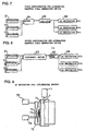
- FIG.s 1 and 2 show the overall configuration of this invention.
- the battery-sorting apparatus of this invention comprises a device 10, which generates a weak magnetostatic field; device 20, which generates an alternating magnetic field; device 30, which detects changes in the strength and the biconstituent phases of the induced magnetic field resulting from the eddy current; signal processor 40; device 60, which arranges and transports the batteries; and sorter 50.
- the battery sorting apparatus in FIG.s 1 and 2 can be connected as a series of sorting apparatuses A, B and C.
- Each of battery sorting apparatuses A, B and C can separate batteries with a specific composition (alkali, manganese, etc.).
- a device could be used which extracted batteries of a given size (D, C, AA, etc.).
- Battery sorting apparatuses A, B and C may be connected in parallel or in series, as needed.
- Examples of device 10, the device which generates a weak magnetostatic field, are shown in FIG.s 4 through 6.
- the device 10 used to generate a weak magnetostatic field shown in the drawings comprises an excitation coil for generating the field and a power supply.
- the coil for generating the field may be cylindrical, horseshoe-shaped or of some other shape.
- FIG. 4 shows a power supply 12 connected to a cylindrical coil 11 through which battery 1 will pass.
- FIG. 5 shows a power supply 15 connected to a horseshoe-shaped coil comprising a horseshoe-shaped magnetic core 13 around which coil 14 is wound.
- FIG. 6 shows a device 10 for generating a weak field which is placed under conveyor belt 16.
- battery 1 is held against belt 16 by the magnetic field, thus assuring that it will remain firmly in place.
- This scheme requires idlers 17 in the vicinity of the field-generating device.
- device 10 generates a weak magnetic field and applies a magnetostatic field to battery 1. This minimizes the effect of magnetic changes (relative magnetic permeability) due to metals in the steel jacket on the battery. It also, as will be discussed shortly, makes it easier to determine the contents of the battery.
- the magnetostatic field must be at least 1 T.
- the configuration of the conveyor can be simplified. This scheme can be used to separate batteries of a wide variety of shapes and sizes.
- Device 10 to generate a weak magnetostatic field is not limited to an electromagnet.
- a permanent magnet could also be employed for this purpose.
- Examples of device 20, the device used to generate an alternating magnetic field, are shown in FIG.s 7 and 8.
- the generating device 20 shown in FIG. 7 comprises oscillators 21, 22 and 23; mixer 24; amplifier 25; and one or more AC excitation coils 26.
- the generating device 20 shown in FIG. 8 comprises oscillators 21, 22 and 23; electronic switch 27; amplifier 25; and one or more AC excitation coils 26.
- the oscillators 21, 22 and 23 should produce signals at low, medium and high frequencies, respectively.
- the response speed will be faster than when they are switched by electronic switch 27.
- the AC excitation coils can also be placed under conveyor belt 16 as shown in FIG 6. Examples of the AC excitation coil 26 are shown in FIG.s 9 and 10.
- FIG. 9 shows a cylindrical AC excitation coil.
- a coil to generate a weak magnetostatic field is combined with a coil to detect changes in the induced magnetic field.
- Battery 1 is dropped into cylindrical guide 71 and moved forward.
- Cylindrical coil 72 which generates a magnetostatic field, is placed outside guide 71. Between guide 71 and coil 72 are cylindrical coil 73, which excites an alternating current, and coil 74, which detects changes in the induced magnetic field.
- the generating coil 72 is connected to DC power supply 75.
- Excitation coil 73 is connected to the amplifier 25 for the device to generate an alternating magnetic field.
- Detector coil 74 is connected to the amplifier 32 for the device to detect changes in the induced magnetic field which is shown in FIG. 1.
- coil 72 applies a relatively weak magnetostatic field to the battery 1 which drops into guide 71
- coil 73 applies an alternating magnetic field.
- Coil 74 detects the changes in the induced magnetic field created by the eddy current induced in battery 1 by the alternating magnetic field.
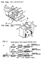
- FIG.s 10 (a) and (b) show local AC excitation coils.
- the drawings show them used with devices to generate a weak magnetostatic field.
- generator coil 82 for the magnetostatic field is placed so that its magnetic flux penetrates battery 1 laterally.
- Local excitation coils 83 which are excited by an alternating current, are placed facing the interior of generator coil 82.
- generator coil 82 applies a weak magnetostatic field to the battery 1 being transported on conveyor belt 81
- local AC excitation coils 83 can apply an alternating magnetic field to the battery.
- Detector coils 84 can then detect the changes in the local field induced in battery 1 by the eddy current created by the alternating field.
- generator coil 93 the coil which generates a magnetostatic field
- generator coil 93 the coil which generates a magnetostatic field
- battery 1 is placed in its gap.
- Local AC excitation coil 94 is placed orthogonal to battery 1.
- generator coil 93 applies a weak magnetostatic field to the battery 1 being transported
- local AC excitation coil 94 can apply an alternating magnetic field to the battery 1.
- Detector coil 95 can then detect the changes in the local field induced in battery 1 by the eddy current created by the alternating field.
- the magnetic field generated by coil 93 in FIG. 10 (b) concentrates the magnetic flux outside the battery in a location facing local AC excitation coil 94. As the magnetization increases, the effect of the eddy current induced in battery 1 will increasingly be experienced in the battery's interior.
- AC excitation coil 26 shown in FIG. 7 can apply a magnetic field which generates an eddy current in the metals constituting the battery.
- the phase-shift and strength of the eddy current which flows in the metals constituting battery 1 will vary according to the electromagnetic characteristics of the metals and the AC frequency. If fields of different frequencies are combined and applied simultaneously, a variety of data can be obtained at one time. This will improve the responsiveness and allow the batteries to be conveyed at a high speed.
- oscillators 21, 22 and 23 apply fields of three separate frequency components simultaneously.
- Using a high (over 100 kHz), medium (10 to 40 kHz) and low (0.5 to 2 kHz) frequency allows us to obtain different detection output at three different frequencies for every battery. If a number of kinds of detection signals are obtained, using a combination of these signals will improve the accuracy with which the batteries are sorted.
- Generating an eddy current by using the local AC excitation coils 83 and 94 which are shown in FIG. 10 allows the configuration of the conveyor to be simplified. If a number of local AC excitation coils of different shapes and sizes are used either coaxially or along the path of transport, the device can be used to sort a wide variety of shapes and sizes of batteries without sacrificing sorting accuracy.
- detector 30 comprises coil 31, which detects changes in the induced magnetic field (hereafter simply called “detecting coil 31”); amplifiers 32a, 32b and 32c; filters 33a, 33b and 33c; and phase discriminators 34a, 34b and 34c.
- detecting coil 31 may comprise separate coils for small and large batteries, and it may be placed under the conveyor belt.
- each selects one of three frequencies, either high, medium or low, which correspond to the frequencies of the oscillators in the device to generate an alternating field.
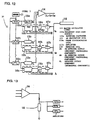
- FIG. 12 An example of the actual configuration of device 30 to detect changes in the induced magnetic field is shown in FIG. 12.
- the device also generates an alternating magnetic field.
- the short-wave (10 MHz) signal from master oscillator circuit 111 is converted to three different frequencies, fH, fM and fL, by frequency step-down circuits 112a, 112b and 112c.
- the three frequencies are converted to sine waves by waveform converters 113a, 113b and 113c. They are mixed by mixer and power amplifier 114, amplified, and output to the AC excitation coil (not shown).
- the signals detected by detector coil 118 are amplified by amplifiers 117a, 117b and 117c. They are then separated into frequencies fH, fM and fL by band pass filters (BPF) 116a, 116b and 116c.
- BPF band pass filters
- Phase discriminators (PSD) 115a, 115b and 115c detect the orthogonal components with respect to reference signals from frequency step-down circuits 112a, 112b and 112c for each of frequencies fH, fM and fL, and output them. In this way detector 30 can detect changes in the induced magnetic field generated by eddy current in battery 1.
- the excitation coil is excited at different frequencies, the output from those frequencies can be detected simultaneously. This improves the responsiveness of the apparatus, and the fact that the signals are simultaneous makes it possible to simplify the configuration of the signal processor.
- the device will be applicable for separating a wide variety of sizes and shapes, both flat and round.
- phase discriminators 34a, 34b and 34c take the orthogonal components of the output signals, the quantity of data is increased (including data relating to both phase and strength), and the accuracy of sorting is improved. In other words, if the orthogonal components of signals at various frequencies are output simultaneously, the quantity of data available for sorting the battery is vastly increased, resulting in more accurate sorting.
- the detecting coil which can be seen in FIG.s 9 and 10, is mounted so as to be coaxial with the AC excitation coil.
- a self-induction coil can be used to achieve the same effect.
- the detecting coil and the AC excitation coil would be a single entity, and, as is shown in FIG. 13, only one portion of the circuit configuration would need to be modified.
- Signal processor 40 which is shown in FIG. 14, comprises device 41, which generates a reference signal, and AND/OR circuits 42, 43 and 44.
- AND/OR circuits 42, 43 and 44 perform "AND” and “OR” operations on the orthogonal component outputs for detection signals associated with the frequencies fH, fM and fL and the outputs of reference signal generator unit 41, which outputs previously determined values for these signals. In this way output is obtained which discriminates among various types of batteries.
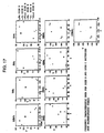
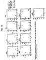
- FIG.s 15 and 16 changes in the detection output for a battery in the absence of a magnetostatic field are shown in FIG.s 15 and 16.
- the orthogonal components of the output signal from the detecting coil for each frequency are plotted as 2-dimensional coordinates on an X-Y axis.
- the size and direction of the vector representing the detection signal will have characteristic values depending on the composition of the battery (whether it consists of manganese (Mn), alkali (Alk), nickel-cadmium (NiCd), etc.) and its size (whether it is D, C, etc.).
- Mn manganese
- Alk alkali
- NiCd nickel-cadmium
- FIG. 17 represents frequency characteristic data for size D and size C batteries in the absence of a magnetostatic field.
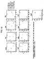
- FIG. 18 represents data for size AA and size AAA batteries in the absence of a magnetostatic field.
- FIG. 19 represents data for size AA and size AAA batteries in the presence of a magnetostatic field of a strength of 0.05 T.
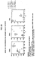
- the method of discriminating types of batteries by combining appropriate frequencies is illustrated in FIG. 20 using the example of how to discriminate an alkaline battery.
- the frequency of the alternating field is 120 kHz, and there is no magnetostatic field
- a D-size alkaline battery will appear in Zone A
- a C-size alkaline battery will appear in Zone D.
- a D-size alkaline battery will appear in Zone B
- a C-size alkaline battery will appear in Zone E.
- a D-size alkaline battery will appear in Zone C
- a C-size alkaline battery will appear in Zone F.
- Signal processor 40 is not limited to the unit pictured in FIG. 14. It could also comprise a multiple-input "AND” circuit, a multiple-input “OR” circuit, and a circuit to generate a reference voltage.
- Another alternative would be to use multiple A/D devices, a digital signal processor, and software which could execute the discrimination protocol described above.
- Device 60 for arranging and conveying the batteries may be a combination of a rotating type and a straight line type conveyor device.
- Device 60 could also comprise a control mechanism to space the batteries at regular intervals as well as a rotating type and a straight line type conveyor device. If the batteries are arranged at fixed intervals to be conveyed to the sorting device by a mechanism to stabilize their positions and thereby prevent the preceeding or following battery from interfering with the one being sorted, the accuracy of sorting will improve.
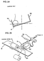
- FIG. 21 One example of an actual arranging and conveying device 60 to arrange and convey the batteries is shown in FIG. 21.
- this arranging and conveying device 60 comprises a rotary-type conveyor device 61 and a straight line-type conveyor device 62.
- Rotary conveyor 61 uses centrifugal force to arrange the batteries 1 which enter the cylinder through inlet 610 and send them to linear conveyor 62.
- Linear conveyor 62 loads the arrayed batteries 1 on conveyor belt 81 and carries them forward.
- Spacing control device 620 shown in FIG. 38 maintains the batteries at regular intervals and loads them on conveyor belt 81.
- revolving conveyor 61 has an oblique disk 612 and a horizontal disk 614 which surrounds the oblique disk. Disks 612 and 614 rotate on an axis which passes through both of them. The outer disk, 614, rotates faster than the inner disk. Disk 612 is rotated by motor 611. Disk 614 is rotated by motor 613, which is on its periphery.
- the battery 1 which enters the conveyor through inlet 610 is loaded on disk 612, is conveyed to the highest portion of the periphery of the disk by centrifugal force, and there exits the disk.
- the battery 1 which has exited disk 612 is loaded onto the peripheral surface of outer disk 614. Centrifugal force lines it up against guide wall 615 as it travels. Batteries 1 are supplied continuously to spacing control device 620 through outlets 616 provided in guide wall 615. Spacing control device 620 is rotated by motor 621 as shown in FIG. 38.
- spacing control disk 623 which has spaces on its periphery into which batteries 1 can fit; linear guide 624, which supplies batteries 1 to spacing control disk 623; and circular guide 625, which is on the periphery of spacing control disk 623.
- the batteries 1 which are continuously supplied from rotary conveyor 61 are continuously arranged along the inside of linear guide 624 and forced onto spacing control disk 623.
- the batteries 1 which are forced onto spacing control disk 623 move into storage space 622, which is along the periphery of the disk. When, in the course of their rotation, they reach an outlet 626, the force of a quantity of air blown from air nozzle 627 supplies them to conveyor belt 81.
- batteries 1 can be supplied to conveyor belt 81 at different intervals.
- the use of this spacing scheme will reduce any effect of adjacent batteries when battery 1 goes past coil 84, the coil which detects changes in the induced magnetic field. This will improve the sorting accuracy.
- conveyor belt 81 is operated by drive motor 66 and a series of pulleys 661. As can be seen in FIG. 24, conveyor belt 81 is mounted obliquely with respect to a horizontal surface. This stabilizes the position of battery 1 along the width of conveyor belt 81 as it is conveyed.
- Sorting device 50 may comprise a number of air nozzles, buckets, and electromagnetic solenoids. It may alternatively comprise a number of sorting arms and an electromagnetic solenoid. As can be seen in FIG. 25, a single unit of sorting device 50 is an element consisting of proximity sensor 51 and electromagnetic valve 52. The entire apparatus would comprise a number of devices which corresponds to the number of types of batteries to be sorted.
- Proximity sensor 51 detects the passage of the battery being transported on conveyor belt 81. When it receives a signal which indicates what type of battery this is, based on the output of proximity sensor 51 and processing executed by signal processor 40, electromagnetic valve 52 directs several high-speed air streams at battery 1. Thus when a battery 1 being transported by conveyor belt 81 is detected by proximity sensor 51 and electromagnetic valve 52 is actuated to expel several high-speed jets of air, the battery is forced off the conveyor belt, sent to the exterior via outlet 65, and supplied to a bin. In this case, while battery 1 is moving, the signal from proximity sensor 51 and the output of signal processor 40 are not simultaneous. Thus the time lag must be corrected by timing adjustor 53 so as to adjust the actuation of valve 52 properly.
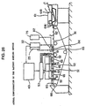
- FIG. 26 An example of an actual battery sorting apparatus which uses a number of the above-described elements is shown in FIG. 26.
- the batteries 1 to be sorted are loaded onto linear conveyor 62 via inlet 610.
- the batteries 1 transported by linear conveyor 62 travel on conveyor belt 81, which is operated by drive motor 66. They are brought past AC excitation coil 83, which comprises generator coil 82, comprising weak magnetostatic field generating device 10 to generate a weak magnetic field, and alternating magnetic field generating device 20, which generates an alternating magnetic field. They also go past detector coil 84, which comprises induced magnetic field change detecting device 30 to detect changes in the induced magnetic field.
- AC excitation coil 83 which comprises generator coil 82, comprising weak magnetostatic field generating device 10 to generate a weak magnetic field, and alternating magnetic field generating device 20, which generates an alternating magnetic field.
- detector coil 84 which comprises induced magnetic field change detecting device 30 to detect changes in the induced magnetic field.
- Coil 82 which generates a weak magnetic field, is connected to DC power supply 75.
- Coil 83 which generates an AC magnetic field, is connected to amplifier 25.
- Coil 84 which detects changes in the induced magnetic field, is connected to amplifier 32. The signal indicating that the battery has been detected is input into signal processing device 40.
- Signal processing device 40 outputs a signal corresponding to what sort of battery this is to timing adjuster 53.
- coil 83 applies an alternating field.
- Coil 84 detects the field induced by the eddy current generated in the battery. If at this time battery 1 should shift in any direction as it is being transported on conveyor belt 81, the distance between it and the detector coil 84 would change, and the accuracy of detection would suffer. It is thus essential that battery 1 not shift about as it is being transported on conveyor belt 81, and that its position be stabilized. As can be seen in FIG. 27, the surface 811 of conveyor belt 81 is tilted at a fixed angle u with respect to horizontal surface 121. However, with this sort of apparatus, the vibration of conveyor belt 81 is liable to cause battery 1 to shift up and down or sideways, as shown by the dotted lines in FIG. 2. This makes it impossible to achieve positional stability.
- FIG. 28 shows a preferred embodiment of a device for stabilizing the position of the battery.
- the device is viewed from a position at a right angle to the direction of transport.
- 1 is the battery transported on conveyor belt 81, which has a guide wall 64 on either side.
- 83 is the coil (hereafter called the “generator coil”) which generates a local alternating magnetic field and applies it to the battery 1.
- 84 is the coil (hereafter called the "detector coil”) for detecting the induced magnetic field generated in and around battery 1 when the alternating field is applied. These coils are placed against the outer surface of the guide wall 64.
- the surface 811 of conveyor belt 81 is tilted at a fixed angle u with respect to horizontal surface 121.
- the magnet 123 is a magnet which is placed on the outer side of the detector coil 84 so that it can exert magnetic force on the battery 1.
- a number of such magnets 123 may be placed along the length of conveyor belt 81, mainly opposite the detector coil 84, or a single magnet may extend over a given length.
- the magnet 123 may be a permanent magnet, or it may be an electromagnet.
- the battery 1 being transported on conveyor belt 81 is on a surface 811 which is tilted as described above. This tilt causes the battery to go to the lowest portion of the surface 811.
- the magnetic force of magnet 123 which is beyond detector coil 84, pulls the battery toward the detector coil.
- the magnet 23 will pull it toward the coil.
- This scheme maintains a fixed distance between the detector coil 84 and battery 1 and thus insures a high accuracy of detection.
- FIG. 29 shows another preferred embodiment of a device for stabilizing the position of the battery. It is viewed from the same perspective as the embodiment in FIG. 28.
- a U-shaped magnet 124 is disposed so that one of its poles 241 is just beyond the detector coil 84.
- conveyor belt 81 which is used to convey the battery 1; the generator coil 83; and detector coil 84.
- the magnet 124 may be a permanent magnet or an electromagnet.
- Other aspects of this configuration are identical to those of the embodiment shown in FIG. 28. Identical components have been given the same reference numbers as in FIG. 28.
- conveyor belt 81 and the battery 1 being transported on the belt 81 are placed in the magnetic gap between poles 241 and 242 of U-shaped magnet 124.
- the magnetic force of pole 241 will draw it toward the detector coil 84.
- the use of a U-shaped magnet 124 makes it more difficult for the field to be interrupted. A strong field is achieved, and battery 1 is reliably drawn close to detector coil 84.
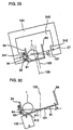
- FIG. 30 shows a third preferred embodiment of a device for stabilizing the position of the battery.
- magnet 123 is placed under conveyor belt 81, which is tilted just as in the previous embodiments. The magnet is placed next to the undersurface 812 of the belt on its lower side.
- the magnet 123 may be a permanent magnet or an electromagnet. Other aspects of this configuration are identical to those of the first embodiment, and have been given the same reference numbers.
- magnet 123 is placed under conveyor belt 81 on its lower side. This means that the attractive force of the magnet 123 draws battery 1 to surface 811 of conveyor belt 81. In the vicinity of the magnet 123, battery 1 will experience much less slippage on surface 811. The frictional coefficient between the battery 1 and conveyor belt 81 is increased. Battery 1 moves in a stable fashion and is reliably drawn close to detector coil 84.
- FIG.s 31 and 32 show a fourth preferred embodiment of a device for stabilizing the position of the battery.
- FIG. 31 is viewed from a location at a right angle to the direction in which the battery travels.
- FIG. 32 is a view of the device in FIG. 31 from the direction of arrow Z.
- a magnet is not used as in the foregoing three embodiments. Instead, battery 1 is brought closer to detector coil 84 mechanically.
- 131 is a position-stabilizing belt. It is mounted in the shape of a triangle on a drive roller 133 and two idler rollers 134.
- 132 is a drive motor. Its output shaft is connected to the drive roller 133.
- the drive motor 132 rotates drive roller 133
- the position-stabilizing belt 131 is conveyed around the three rollers 133 and 134.
- the drive motor 132, drive roller 133, the two idle rollers 134 and the position-stabilizing mechanism mounted on these rollers are all mounted on elevator 135.
- the elevator 135 moves up and down as shown by the arrow in the drawing, its stabilizing belt 131 exerts pressure on the exterior of battery 1.
- the position-stabilizing mechanism 100 as shown in FIG.
- the guide wall 64 is shaped like an angular letter "U", of which the flat bottom forms floor 641.
- the conveyor belt 81 runs on the floor 641.
- elevator 135 lowers it as shown by the arrow in FIG. 32.
- the battery 1 is pushed by a fixed pressure toward the lower interior surface of guide wall 64 and toward that portion of surface 811 of conveyor belt 81 which is closest to the detector coil 84. In this way the battery 1 is always brought close to the detector coil 84, and its position is stabilized.
- this embodiment no magnet is used. Instead, battery 1 is brought close to detector coil 84 mechanically. This eliminates the noise which interferes with the detection signal from detector coil 84 when a magnet is used, thus allowing a high accuracy of detection to be maintained.
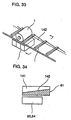
- FIG.s 33 and 34 show a fifth preferred embodiment of a device for stabilizing the position of the battery.
- FIG. 33 is a perspective drawing
- FIG. 34 is a cross section taken along line Y-Y in FIG. 33.
- a so-called "trough" conveyor belt 81 has projections or ribs 141 at fixed intervals along its length.
- the upper surface of the belt 81 has projections 141 at regular intervals, and the projections go all the way across the belt.
- the spacing or pitch of the projections 141 is such that a battery 1 can be loaded between two projections 141 so that it cannot move at all along the length of the belt.
- each angled surface at the base of the projections 141 is lower, and the portion which is opposite the coil is higher. This causes battery 1 to move to the lower portion of the slanted surface 142, where it is closer to the detector coil 84. In this way, a battery 1 being transported on conveyor belt 81 will always go to the lower portion of the slanted surface 142 between the projections 141. In other words, it will always fall into a position quite close to detector coil 84.
- FIG. 35 is a rough side view of a sixth preferred embodiment of a device for stabilizing the position of the battery.
- This embodiment is a modified version of the fifth embodiment.
- Conveyor belt 151 has a wavy surface with valleys 152 in which batteries 1 can fit.
- the detector coil is placed below one of the valleys 152. With this design, the battery 1 on conveyor belt 151 is above detector coil 84 and inevitably approaches quite near the detector coil 84.
- FIG. 36 is a side view of a seventh preferred embodiment of a device for stabilizing the position of the battery.
- belt 161 has magnetic powder glued to its surface.
- Battery 1 is loaded onto the magnetic belt 161 and transported.
- 161 is the belt on which a coating of magnetic powder has been glued.
- the detector coil 84 is placed near the side of the magnetic belt 161.
- 163 is the air shooter belt placed upstream from the magnetic belt 161; 164 is the ordinary rubber belt downstream from the magnetic belt 161 which expels the battery.
- the battery 1 which is transported from air shooter 163 by magnetic belt 161 is temporarily fixed to the belt 161 by its magnetic force.
- FIG. 37 is a plan view of the essential parts of an eighth preferred embodiment of a device for stabilizing the position of the battery.
- Detector coil 84 is placed on the side of the conveyor where the path is narrowed by the guide panel 171.
- the guide panel 171 is formed by removing a portion of guide wall 64 on conveyor belt 81.
- Battery 1 is guided by interior wall 172 to a position facing detector coil 84. The portion of the path in front of the detector coil 84 is gradually contracted so that it becomes more narrow.
- battery 1 is mechanically guided by guide panel 171 so that it arrives in a reliable fashion at a location near detector coil 84.
- This scheme uses a simple configuration to achieve a stable transport and positioning of the battery.
- FIG. 38 illustrates a preferred embodiment of a spacing control device for spacing the batteries at equal intervals.
- batteries 1 are continuously expelled from outlet 616 of the rotary conveyor and travel along until they are stopped by rotary control disk 623 inside linear guide 624.
- Rotary control disk 623 has a space 622 on its periphery in which a single battery will fit. When the disk rotates, the battery in space 622 moves toward conveyor belt 81. When this battery 1 reaches outlet 626, which is on a portion of round guide 625, a jet of air blown out of air nozzle 627 loads it onto conveyor belt 81.
- outlet 626 which is on a portion of round guide 625
- a jet of air blown out of air nozzle 627 loads it onto conveyor belt 81.
- the basic invention comprises a method of sorting batteries in which a weak magnetostatic field and an alternating magnetic field containing numerous frequency components are applied to a continuously conveyed battery.
- the induced magnetic field created by the eddy current induced in the battery is then detected.
- the strength of the induced magnetic field and the orthogonal components of its phase are measured with respect to the alternating field.
- the battery is then sorted according to type and size. In this way all types of batteries can be sorted according to size and principal components without applying a saturation field to the battery.
- the strength of the magnetostatic field is reduced to 1/10 that used in the prior art. This reduces the resistance of the battery on the conveyor and allows it to be transported smoothly without reducing the accuracy with which the induced magnetic field can be detected.
- the invention also includes an embodiment comprising a method for sorting batteries in which an alternating magnetic field containing numerous frequency components is applied to a continuously conveyed battery. The induced magnetic field created by the eddy current induced in the battery is then detected. The strength of the induced magnetic field and the orthogonal components of its phase are measured with respect to the alternating field. Based on the relationship between the type and size of the battery with respect to the orthogonal components which were previously obtained, the battery is then sorted according to type and size. This method enables the device for generating a weak magnetic field to be omitted.
- the relationship between the classification and size of the battery and the measured parameters comprises a plurality of measured tolerance ranges
- the relationship between the type and size of the battery and the strength and phase of its induced magnetic field has a fixed tolerance range for every frequency of the alternating field.
- the transport of the batteries is not interfered with.
- the batteries can be conveyed at a high speed.
- an obliquely oriented first disk and a horizontal second disk surrounding the first are rotated on an axis which intersects both disks.
- the outer disk is rotated faster than the inner disk.
- Each battery is inserted into the disks, which results in the batteries being lined up with fixed intervals between them.
- This row of batteries is conducted via a conveyor belt past a device which generates an alternating magnetic field and one which detects changes in the induced magnetic field.
- This device detects changes in the strength and phase of the induced magnetic field which are due to the composition of the battery for at least three sorts of frequency components.
- a signal processing device performs "AND” and "OR” operations on the data which are detected, and outputs them as a signal corresponding to what sort of battery this is. This output is used to send each sort of battery to a specific location.
- This method embodiment utilizes a simplified apparatus.
- all types of batteries can be sorted according to size and principal components without applying a saturating field to the battery.
- the batteries are stabilized in position as they pass the coil. This improves the accuracy with which the batteries are sorted.
- the coil used as the device to generate an alternating magnetic field and the coil used as the device to detect changes in the induced magnetic field are the sort of coil which induces a local field.
- a larger and a smaller coil can be arranged on the same shaft and used together to detect larger and smaller batteries. This improves the accuracy with which the apparatus can sort batteries of different sizes.
- the apparatus is configured with a U-shaped magnet and the conveyor belt passes betweenthe poles of the magnet, it is less likely for the magnetic field to be interrupted and a stronger field is achieved. The passage of the battery thus is further stabilized.
- the apparatus is configured so that the induced magnetic field is detected from beside the conveyor belt and and the magnet is placed below the conveyor, the battery is drawn toward the conveyor surface. This increases the frictional coefficient between the battery and the surface of the conveyor, thus further stabilizing the passage of the battery.
- the battery is brought closer to the detection means by a mechanical device. This eliminates the problem of noise getting into the signal from the detection means which occurs when a magnet is used. It also stabilizes the transport of the battery.
- the battery With the embodiment of the apparatus according to the invention in which the battery is carried on a magnetic belt, the battery is attracted toward the belt surface. This prevents any relative movement as the induced magnetic field is detected. It thus stabilizes the transport of the battery and maintains a high accuracy of detection.
- the batteries are transported on the conveyor belt with fixed intervals between them.
- the signal for each battery can be detected without being affected by adjacent batteries, so the accuracy of sorting is improved.
Landscapes
- Engineering & Computer Science (AREA)
- Manufacturing & Machinery (AREA)
- Chemical & Material Sciences (AREA)
- Chemical Kinetics & Catalysis (AREA)
- Electrochemistry (AREA)
- General Chemical & Material Sciences (AREA)
- Life Sciences & Earth Sciences (AREA)
- Sustainable Development (AREA)
- Sorting Of Articles (AREA)
- Investigating Or Analyzing Materials By The Use Of Magnetic Means (AREA)
- Secondary Cells (AREA)
Applications Claiming Priority (4)
| Application Number | Priority Date | Filing Date | Title |
|---|---|---|---|
| JP34831398 | 1998-12-08 | ||
| JP34831398 | 1998-12-08 | ||
| JP23467199 | 1999-08-20 | ||
| JP23467199A JP3443043B2 (ja) | 1998-12-08 | 1999-08-20 | 電池分別方法及びその装置 |
Publications (2)
| Publication Number | Publication Date |
|---|---|
| EP1009049A2 true EP1009049A2 (de) | 2000-06-14 |
| EP1009049A3 EP1009049A3 (de) | 2001-01-03 |
Family
ID=26531693
Family Applications (1)
| Application Number | Title | Priority Date | Filing Date |
|---|---|---|---|
| EP99124413A Withdrawn EP1009049A3 (de) | 1998-12-08 | 1999-12-07 | Verfahren und Vorrichtung zur Klassifizierung und Wiedergewinnung der Hauptbestandteile gebrauchter Batterien |
Country Status (4)
| Country | Link |
|---|---|
| US (2) | US6337450B1 (de) |
| EP (1) | EP1009049A3 (de) |
| JP (1) | JP3443043B2 (de) |
| CA (1) | CA2291982C (de) |
Cited By (13)
| Publication number | Priority date | Publication date | Assignee | Title |
|---|---|---|---|---|
| EP2394317A4 (de) * | 2009-02-05 | 2014-04-16 | Magna Lastic Devices Inc | Batterieladezustandssensor |
| WO2014102011A1 (de) * | 2012-12-28 | 2014-07-03 | D.Evolute Forschungs- Und Entwicklungsgesellschaft Br | Verfahren zum erkennen und klassifizieren von elektromagnetisch detektierbaren teilen, insbesondere von fördergutteilen in einem schüttgut |
| CN105044620A (zh) * | 2015-08-27 | 2015-11-11 | 浙江杭可科技有限公司 | 软包锂离子电池开路电压内阻测定设备 |
| EP2960669A4 (de) * | 2013-02-25 | 2016-04-13 | Nissan Motor | Magnetauswertungsvorrichtung und -verfahren |
| CN108126908A (zh) * | 2017-12-30 | 2018-06-08 | 熊玉金 | 测量垫片厚度的检测装置 |
| CN108144866A (zh) * | 2017-12-30 | 2018-06-12 | 熊玉金 | 测量传动蜗杆长度的检测装置 |
| CN108144864A (zh) * | 2017-12-30 | 2018-06-12 | 熊玉金 | 传动蜗杆次品检测装置 |
| CN110153035A (zh) * | 2018-01-16 | 2019-08-23 | 江苏经贸职业技术学院 | 一种物流分拣用双螺旋自动拣货装置 |
| CN111632883A (zh) * | 2020-06-11 | 2020-09-08 | 北京中航科电测控技术股份有限公司 | 一种用于电池组的集成视觉检测装置及其检测方法 |
| WO2024020336A1 (en) * | 2022-07-18 | 2024-01-25 | Li Industries, Inc. | Methods and systems for advanced battery collection, sorting, and packaging |
| WO2025144739A1 (en) * | 2023-12-29 | 2025-07-03 | Gopher Resource, LLC | Battery identification systems and methods |
| WO2025188191A1 (en) | 2024-03-06 | 2025-09-12 | Li-Tech As | A waste detection assembly |
| US12521766B1 (en) | 2019-02-27 | 2026-01-13 | Li Industries, Inc. | Smart systems and methods for identification and processing of spent lithium cells |
Families Citing this family (26)
| Publication number | Priority date | Publication date | Assignee | Title |
|---|---|---|---|---|
| US6781344B1 (en) * | 2003-02-11 | 2004-08-24 | Fuji Photo Film, Inc. | Battery tester and sorting apparatus |
| WO2006042000A2 (en) * | 2004-10-06 | 2006-04-20 | Ener1 Group, Inc. | Method and apparatus for electromagnetic-based quality inspection of battery dry electrode structure |
| JP5179152B2 (ja) * | 2007-11-27 | 2013-04-10 | 株式会社オーイズミ | 遊技媒体払出装置 |
| CN101497399A (zh) * | 2008-01-29 | 2009-08-05 | 鸿富锦精密工业(深圳)有限公司 | 自动分料机 |
| US8872519B2 (en) * | 2008-09-26 | 2014-10-28 | GM Global Technology Operations LLC | System and method to determine the state of charge of a battery using magnetostriction to detect magnetic response of battery material |
| JP5373541B2 (ja) * | 2009-10-16 | 2013-12-18 | 国立大学法人信州大学 | 金属部品の磁界検出センサー及び金属部品の良否判定方法 |
| KR101348192B1 (ko) * | 2012-06-11 | 2014-01-06 | 이시자키코리아 주식회사 | 와류탐상검사에 의한 이차 건전지용 캔의 자동검사장치 |
| CN107890950B (zh) * | 2015-10-27 | 2019-11-12 | 张荣斌 | 一种矿山用磁选机的自动控制系统 |
| CN108237090B (zh) * | 2016-12-23 | 2024-05-03 | 惠州市德赛自动化技术有限公司 | 一种电芯模组自动分选机 |
| JP6822357B2 (ja) * | 2017-09-19 | 2021-01-27 | トヨタ自動車株式会社 | 電池の異常診断方法 |
| CN108736088B (zh) * | 2018-05-30 | 2024-02-23 | 武汉动力电池再生技术有限公司 | 电池包自动化拆解系统 |
| CN108735964B (zh) * | 2018-07-28 | 2023-08-29 | 东莞市德瑞精密设备有限公司 | 具有长静置时间的软包锂电池注液机 |
| CN111111909B (zh) * | 2020-02-08 | 2021-10-15 | 青岛大学 | 散装物料铁磁杂质清除装置 |
| CN111701868A (zh) * | 2020-06-16 | 2020-09-25 | 苏州嘉诺智能装备有限公司 | 废旧电池分选方法及废旧电池分选系统 |
| CN112090790A (zh) * | 2020-08-25 | 2020-12-18 | 夏松松 | 一种自动检测锂电池充放状态的设备 |
| CN111940134B (zh) * | 2020-08-27 | 2024-12-03 | 广西玉柴机器股份有限公司 | 一种发动机铸件披锋铁回收系统及控制方法 |
| CN112044812A (zh) * | 2020-08-31 | 2020-12-08 | 惠州市力晟达新能源科技有限公司 | 一种纽扣电池电量检测分类装置 |
| CN112387625A (zh) * | 2020-12-10 | 2021-02-23 | 东莞市恒易电子科技有限公司 | 一种电感测试装置 |
| CN112871695B (zh) * | 2020-12-15 | 2024-03-08 | 深圳市中科德睿智能科技有限公司 | 电池检测设备 |
| CN113714107A (zh) * | 2021-07-30 | 2021-11-30 | 广东嘉尚新能源科技有限公司 | 一种可提高测试精度的软包锂电芯用表面鼓包平整度检测装置 |
| CN113976461B (zh) * | 2021-12-29 | 2022-03-01 | 常州市桑豪车辆配件有限公司 | 一种可持续运行的数字化印刷品分离装置及其分离工艺 |
| CN116500962B (zh) * | 2023-06-29 | 2024-03-29 | 南京航空航天大学 | 锂电池机器人拆解控制方法及其系统 |
| CN116966988B (zh) * | 2023-07-28 | 2024-04-05 | 烟台大为环保科技有限公司 | 一种锂电池用破碎系统 |
| CN117410609B (zh) * | 2023-12-15 | 2024-02-27 | 山西迪诺思新能源科技有限公司 | 一种新能源汽车废旧动力电池的梯次利用方法 |
| CN119447553A (zh) * | 2024-11-08 | 2025-02-14 | 合肥综合性国家科学中心能源研究院(安徽省能源实验室) | 一种锂离子电池负极极片的高值精选方法 |
| CN120703587B (zh) * | 2025-06-26 | 2026-04-21 | 哈尔滨工业大学 | 一种基于磁场时序变化特征的电池评估方法与筛分方法 |
Family Cites Families (14)
| Publication number | Priority date | Publication date | Assignee | Title |
|---|---|---|---|---|
| US2383008A (en) * | 1942-06-01 | 1945-08-21 | Meister Leo | Work positioning apparatus |
| US2920739A (en) * | 1958-05-02 | 1960-01-12 | Alfred M Woldin | Container or article divider |
| JPS5997862A (ja) * | 1982-11-24 | 1984-06-05 | 株式会社日立製作所 | 部品供給装置 |
| DE3928017A1 (de) * | 1989-08-24 | 1991-03-07 | Kronseder Maschf Krones | Verfahren und vorrichtung zum umformen eines mehrspurigen behaelterstromes in einen einspurigen behaelterstrom |
| JP3005060B2 (ja) * | 1991-01-28 | 2000-01-31 | 松下電工株式会社 | カード式プログラムタイマ |
| EP0578688B1 (de) | 1991-04-04 | 1995-06-21 | Titalyse S.A. | Verfahren und vorrichtung zum sortieren von gebrauchten batterien und akkumulatoren |
| US6285185B1 (en) * | 1992-07-22 | 2001-09-04 | U.S. Philips Corporation | Apparatus and method for determining the type of a battery or accumulator by use of magnetic fields |
| EP0580241B1 (de) | 1992-07-22 | 1996-10-02 | Koninklijke Philips Electronics N.V. | Gerät und Verfahren zur Bestimmung des Typs einer Batterie oder eines Akkumulators |
| US5626233A (en) * | 1995-03-07 | 1997-05-06 | Venturedyne, Ltd. | Eddy current separator |
| JP3137286B2 (ja) | 1996-03-05 | 2001-02-19 | キヤノン株式会社 | 密閉型電池部材の回収方法及び回収装置 |
| FR2760276B1 (fr) * | 1997-02-28 | 1999-04-23 | Pechiney Recherche | Dispositif et methode de detection, d'identification et de tri d'emballages metalliques ou comprenant une partie metallique |
| JP3935594B2 (ja) | 1997-03-14 | 2007-06-27 | 三菱重工業株式会社 | 非水溶媒系電池の処理方法 |
| JP3812136B2 (ja) * | 1998-04-23 | 2006-08-23 | 松下電器産業株式会社 | 電池用自動重量選別機 |
| US6325198B1 (en) * | 1998-06-26 | 2001-12-04 | Eveready Battery Company, Inc. | High speed manufacturing system |
-
1999
- 1999-08-20 JP JP23467199A patent/JP3443043B2/ja not_active Expired - Fee Related
- 1999-12-07 CA CA 2291982 patent/CA2291982C/en not_active Expired - Fee Related
- 1999-12-07 EP EP99124413A patent/EP1009049A3/de not_active Withdrawn
- 1999-12-08 US US09/456,562 patent/US6337450B1/en not_active Expired - Fee Related
-
2001
- 2001-11-09 US US09/986,703 patent/US6677547B2/en not_active Expired - Fee Related
Cited By (17)
| Publication number | Priority date | Publication date | Assignee | Title |
|---|---|---|---|---|
| EP2394317A4 (de) * | 2009-02-05 | 2014-04-16 | Magna Lastic Devices Inc | Batterieladezustandssensor |
| US9086460B2 (en) | 2009-02-05 | 2015-07-21 | Methode Electronics, Inc. | Apparatus and method for monitoring the state of charge of a battery cell |
| WO2014102011A1 (de) * | 2012-12-28 | 2014-07-03 | D.Evolute Forschungs- Und Entwicklungsgesellschaft Br | Verfahren zum erkennen und klassifizieren von elektromagnetisch detektierbaren teilen, insbesondere von fördergutteilen in einem schüttgut |
| EP2960669A4 (de) * | 2013-02-25 | 2016-04-13 | Nissan Motor | Magnetauswertungsvorrichtung und -verfahren |
| US9625539B2 (en) | 2013-02-25 | 2017-04-18 | Nissan Motor Co., Ltd. | Magnet evaluating device and method |
| CN105044620A (zh) * | 2015-08-27 | 2015-11-11 | 浙江杭可科技有限公司 | 软包锂离子电池开路电压内阻测定设备 |
| CN105044620B (zh) * | 2015-08-27 | 2018-02-02 | 浙江杭可科技股份有限公司 | 软包锂离子电池开路电压内阻测定设备 |
| CN108144866A (zh) * | 2017-12-30 | 2018-06-12 | 熊玉金 | 测量传动蜗杆长度的检测装置 |
| CN108126908A (zh) * | 2017-12-30 | 2018-06-08 | 熊玉金 | 测量垫片厚度的检测装置 |
| CN108144864A (zh) * | 2017-12-30 | 2018-06-12 | 熊玉金 | 传动蜗杆次品检测装置 |
| CN110153035A (zh) * | 2018-01-16 | 2019-08-23 | 江苏经贸职业技术学院 | 一种物流分拣用双螺旋自动拣货装置 |
| US12521766B1 (en) | 2019-02-27 | 2026-01-13 | Li Industries, Inc. | Smart systems and methods for identification and processing of spent lithium cells |
| CN111632883A (zh) * | 2020-06-11 | 2020-09-08 | 北京中航科电测控技术股份有限公司 | 一种用于电池组的集成视觉检测装置及其检测方法 |
| CN111632883B (zh) * | 2020-06-11 | 2020-12-29 | 北京中航科电测控技术股份有限公司 | 一种用于电池组的集成视觉检测装置及其检测方法 |
| WO2024020336A1 (en) * | 2022-07-18 | 2024-01-25 | Li Industries, Inc. | Methods and systems for advanced battery collection, sorting, and packaging |
| WO2025144739A1 (en) * | 2023-12-29 | 2025-07-03 | Gopher Resource, LLC | Battery identification systems and methods |
| WO2025188191A1 (en) | 2024-03-06 | 2025-09-12 | Li-Tech As | A waste detection assembly |
Also Published As
| Publication number | Publication date |
|---|---|
| CA2291982C (en) | 2005-10-25 |
| US6337450B1 (en) | 2002-01-08 |
| US20020027095A1 (en) | 2002-03-07 |
| CA2291982A1 (en) | 2000-06-08 |
| EP1009049A3 (de) | 2001-01-03 |
| US6677547B2 (en) | 2004-01-13 |
| JP3443043B2 (ja) | 2003-09-02 |
| JP2000229269A (ja) | 2000-08-22 |
Similar Documents
| Publication | Publication Date | Title |
|---|---|---|
| CA2291982C (en) | Method and apparatus for classifying and recovering the main components of used batteries | |
| US6168001B1 (en) | Positive drive coin discrimination apparatus and method | |
| CN1159683C (zh) | 硬币处理装置和一种包含该装置的硬币存储机 | |
| US20050040007A1 (en) | Coin processing machine and method for discriminating coins of varied composition, thickness, and diameter | |
| WO1998000814A1 (en) | Positive drive coin discrimination apparatus and method | |
| JPH084759B2 (ja) | 磁石式分離機 | |
| WO1993004448A1 (en) | Coin discrimination apparatus | |
| AU2012338891B2 (en) | Conveyor device for coins | |
| JP3549052B2 (ja) | 選別装置 | |
| US5829600A (en) | Method and apparatus for identifying different, elongated metallic objects | |
| JP2005342651A (ja) | 選別装置 | |
| JP2000343044A (ja) | 物体の供給装置 | |
| JPH06273535A (ja) | 金属検出装置および金属除去装置 | |
| JP3603353B2 (ja) | 廃びんの色選別装置 | |
| EP0694889A2 (de) | Vorrichtung zum Beurteilen eines Banknotenzustandes | |
| US20020058471A1 (en) | Coin sorting machine | |
| GB2357886A (en) | Apparatus for coin discrimination | |
| JPH07120452B2 (ja) | 硬貨処理機における硬貨識別装置 | |
| JPH10143713A (ja) | 硬貨処理機 | |
| JPH08131965A (ja) | 金属分離装置 | |
| JPH0435976Y2 (de) | ||
| JP2936986B2 (ja) | 硬貨処理機 | |
| JP2007050936A (ja) | パーツフィーダ | |
| KR20250064350A (ko) | 스크랩 선별 장치 | |
| EP0665970B1 (de) | Vorrichtung und verfahren zum fördern von münzen |
Legal Events
| Date | Code | Title | Description |
|---|---|---|---|
| PUAI | Public reference made under article 153(3) epc to a published international application that has entered the european phase |
Free format text: ORIGINAL CODE: 0009012 |
|
| AK | Designated contracting states |
Kind code of ref document: A2 Designated state(s): AT BE CH CY DE DK ES FI FR GB GR IE IT LI LU MC NL PT SE |
|
| AX | Request for extension of the european patent |
Free format text: AL;LT;LV;MK;RO;SI |
|
| PUAL | Search report despatched |
Free format text: ORIGINAL CODE: 0009013 |
|
| RIC1 | Information provided on ipc code assigned before grant |
Free format text: 7H 01M 6/52 A, 7H 01M 10/54 B, 7B 07C 5/344 B, 7G 01N 27/72 B, 7B 03B 9/06 B |
|
| AK | Designated contracting states |
Kind code of ref document: A3 Designated state(s): AT BE CH CY DE DK ES FI FR GB GR IE IT LI LU MC NL PT SE |
|
| AX | Request for extension of the european patent |
Free format text: AL;LT;LV;MK;RO;SI |
|
| 17P | Request for examination filed |
Effective date: 20010628 |
|
| AKX | Designation fees paid |
Free format text: AT BE CH CY DE DK ES FI FR GB GR IE IT LI LU MC NL PT SE |
|
| 17Q | First examination report despatched |
Effective date: 20061002 |
|
| STAA | Information on the status of an ep patent application or granted ep patent |
Free format text: STATUS: THE APPLICATION IS DEEMED TO BE WITHDRAWN |
|
| 18D | Application deemed to be withdrawn |
Effective date: 20070413 |