EP1009207A2 - Boítier pour un équipement électrique - Google Patents
Boítier pour un équipement électrique Download PDFInfo
- Publication number
- EP1009207A2 EP1009207A2 EP99309843A EP99309843A EP1009207A2 EP 1009207 A2 EP1009207 A2 EP 1009207A2 EP 99309843 A EP99309843 A EP 99309843A EP 99309843 A EP99309843 A EP 99309843A EP 1009207 A2 EP1009207 A2 EP 1009207A2
- Authority
- EP
- European Patent Office
- Prior art keywords
- door
- resilient
- housing
- housing according
- frame
- Prior art date
- Legal status (The legal status is an assumption and is not a legal conclusion. Google has not performed a legal analysis and makes no representation as to the accuracy of the status listed.)
- Withdrawn
Links
Images


Classifications
-
- H—ELECTRICITY
- H05—ELECTRIC TECHNIQUES NOT OTHERWISE PROVIDED FOR
- H05K—PRINTED CIRCUITS; CASINGS OR CONSTRUCTIONAL DETAILS OF ELECTRIC APPARATUS; MANUFACTURE OF ASSEMBLAGES OF ELECTRICAL COMPONENTS
- H05K5/00—Casings, cabinets or drawers for electric apparatus
- H05K5/10—Casings, cabinets or drawers for electric apparatus comprising several parts forming a closed casing
- H05K5/15—Casings, cabinets or drawers for electric apparatus comprising several parts forming a closed casing assembled by resilient members
Definitions
- This invention relates to improvements in housings for electrical equipment, and in particular but not exclusively to housings for both low voltage and high voltage electrical circuitry such as a motor controller.
- a typical user may have several units controlling several electrical motors in a process. It is therefore desirable to make the housing as compact as possible so as to minimise space requirements.
- the housing should also be attractive and provide convenient access to its contents.
- housing for electrical equipment comprising a casing and a door of which at least a part is made of resilient material, the door being adapted to pivot about a hinge along one edge relative to the casing for movement between an open and a closed position, said door being adapted to engage the casing when it is closed position and adapted to be disengaged and moved to an open position by resilient deformation of the door and characterised in that the resilient door is hinged to a second door which in turn is hinged to the frame to provide a two-stage entry.
- the door comprises a one piece plastics component. It may conveniently be extruded or otherwise moulded. The whole door may therefore be constructed from a resilient material.
- the provision of two doors provides a two-stage entry to the housing.
- the two doors may sit side by side when they are both closed, i.e. be in parallel.
- the door may be extruded as a single piece of indefinite length. It can then be cut down to the appropriate length depending on the size of the casing to which it is to be incorporated.
- the casing comprises a pressed metal frame formed at least partially from sheet metal.
- the frame may also serve as a chassis for one or more of the electrical components to be held in the frame. It may be adapted to enable the frame to be rack mounted.
- the resilient door preferably has a substantially U-shaped cross section with a substantially flat elongated base portion.
- One side of the U-shape may be hinged to a first side wall of the frame, the other side resiliently engaging with an inner face of the second side wall of the frame.
- An end of the second side wall of the frame may be folded back on itself to avoid a sharp edge.
- a flange formed on the unhinged side of the U-shaped door section may engage behind the folded back portion of the frame to hold the door latched in its closed position.
- One advantage of providing a sheet metal frame and a resilient door is that it enables a row of similar units to be placed side by side with no space required between the side panels to open the door.
- the walls of the frame are only thin sheet metal, producing a narrow structure.
- the resilient door In a first stage, the resilient door can be deformed and opened without tools to access a first portion of the housing.
- This portion may contain, for example, low voltage equipment.
- the second door may be opened to gain access to a further part of the housing. This may contain high voltage equipment. If so, it is desirable that the second door can only be opened using suitable tools (i.e. tool access) to meet safety requirements.
- the first door must be opened to gain access to a lock mechanism (such as a key-operated lock or a slot headed bolt) for the second door.
- Safety warning labels may also be provided either on the rear side of the first (resilient) door or behind the resilient door within the housing. Both alternatives are preferred as it ensures that when both doors are closed the warnings are hidden from view, yet must be seen to access the second door. The second door cannot be unlocked when the first door is closed.
- the resilient door need not be hinged to the first door as long as it covers the lock for the second door when it is closed.
- first and second doors may hinge about one or more vertical hinge pins so they each pivot about a respective vertical axis.
- horizontal opening is possible.
- the flange on the unhinged side of the resilient door may be tapered so that it automatically engages with the inside of the frame when pushed shut, i.e. the end of the U-shaped cross-section may taper slightly inwardly.
- a small cut-out may be provided in the top edge of the resilient door into which a finger can be inserted. As the door is pulled at this point, it bows slightly allowing it to open.
- a plurality of ridges or grooves extend along the length of the resilient door. These help to detract the eye from any scratches or irregularities on the door allowing a low cost manufacturing process to be employed.
- the hinged edge of the resilient door may be formed into a C-shaped channel adapted to clip over a hinge pin secured relative to the second door to form the hinge.
- the resilient door may therefore be a snap-fit along its hinged edge to the rest of the casing. Again, this results in a simple low cost extrusion to be used.
- the C-shaped section may be continuous along its length.
- the invention provides a set of housings for electrical equipment, in which each housing comprises a casing having different external dimensions and incorporating a resilient hinged door of a predetermined width irrespective of the width of the housing.
- the invention provides a motor controller comprising an electrical circuit accommodated within a housing in accordance with the first aspect of the invention.
- a single width of door can be used in a range of casing sizes. This allows an extrusion process to be used to produce a standard door which fits a range of different size casings.
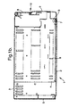
- Figures 1 to 3 show a housing 1 in several positions viewed (a) in perspective and (b) from overhead.
- the housing comprises a frame formed from pressed steel sheets bolted together at various points along the edges.
- the frame is shown in the figures with its top panel omitted for clarity and comprises two planar side panels 2, 3 and a base panel 4 and back plate 5.
- the rear edges of the side panels are secured to the back plate by a number of screws in this example, although rivets could be used instead.
- the base plate 5 also incorporates slots 6 to allow cooling air to enter the cabinet.
- the metal frame is tall relative to its width, although the housing may be produced in a range of sizes and shapes suitable, for example, for rack mounting.
- the front edge of the left-hand side panel is folded back inside itself to form a smooth leading edge, providing a small flange 7 along its length inside of the panel.
- the front of the housing is covered by a two stage door system.
- This comprises a first metal door 8 hinged along one edge to the right-hand side panel 3 of the frame.
- the metal door 8 extends along the full height of the frame and is approximately half of the width of the frame.
- the metal door 8 In its closed position, the metal door 8 is secured to a portion of the base of the frame by a bolt (not shown) engaging a threaded opening in the base. This ensures that access to the right hand side of the casing via the door 8 is only possible using tools.
- a second door 9 is hingedly attached along the free edge of the first door furthest from its hinge. This door can be pivoted about its hinged side to gain access to the left-hand side of the casing.
- the second door 9 comprises a one-piece plastics extrusion having a substantially uniform cross-section along its length. In practice, a continuous extrusion is produced, and a suitable length portion is cut-off to form the second door.
- the extrusion has a substantially U-shaped cross-section, the elongated base of the U forming the front of the door and one side of the section defining a portion of a hinge assembly 10. As shown, this portion is formed into a c-shaped section 11 which clips onto a hinge pin 12 provided on the first door 8.
- the other side of the U-shaped extrusion is configured as an extended flange 13 so that it engages with the turned back flange of the left-hand side panel of the frame. This secures the second door 9 in a closed position and prevents accidental release.
- the second door 9 is resilient, it can be opened by simply deforming the door. This can either be by deforming the flanged side towards the hinged side, or by bowing the base of the U-shaped door or both. Only a light pressure, such as can be applied by hand, is needed to open the door.
- the hinged resilient door also incorporates several raised strips or ridges moulded along its length. These help to draw the eye from any defects in the shape of the extrusion, which may occur during production.
- the resilient door 9 is shorter than the first door 8, and extends from the base of the front of the frame only part way towards the top panel.
- the space above the resilient door provides for the convenient location of a hand-held control pad (not shown) or a bank of control switches.
- the casing accommodates both low voltage and high voltage electrical circuitry such as that provided in a motor controller for an industrial a.c. induction motor.
- the low voltage and high voltage circuitry can be conveniently split into two stages: the low voltage circuitry located behind the resilient door and the high voltage behind the locked door.
- the resilient door 9 By opening the resilient door 9, access can be gained to the low voltage components. To access the high voltage components, the resilient door 9 must be open to gain access to the bolt for the door 8. Thus, by providing safety warnings on the inside of the door the user is given the notice required by safety legislation without having unsightly warnings on display in normal use (when the resilient door is closed).
- Providing the two doors in parallel, one hinged from the free edge of the other is also advantageous in that it allows a range of widths of casings to be produced using a standard extrusion moulding for the resilient door. For different widths, only the locked door (which can be a simple metal pressing) needs to be of a variable width. Thus, production and trading costs are minimised.
Landscapes
- Engineering & Computer Science (AREA)
- Microelectronics & Electronic Packaging (AREA)
- Casings For Electric Apparatus (AREA)
Applications Claiming Priority (2)
| Application Number | Priority Date | Filing Date | Title |
|---|---|---|---|
| GB9826837 | 1998-12-07 | ||
| GB9826837A GB2344696A (en) | 1998-12-07 | 1998-12-07 | A housing for electrical equipment |
Publications (2)
| Publication Number | Publication Date |
|---|---|
| EP1009207A2 true EP1009207A2 (fr) | 2000-06-14 |
| EP1009207A3 EP1009207A3 (fr) | 2001-03-07 |
Family
ID=10843744
Family Applications (1)
| Application Number | Title | Priority Date | Filing Date |
|---|---|---|---|
| EP99309843A Withdrawn EP1009207A3 (fr) | 1998-12-07 | 1999-12-07 | Boítier pour un équipement électrique |
Country Status (2)
| Country | Link |
|---|---|
| EP (1) | EP1009207A3 (fr) |
| GB (1) | GB2344696A (fr) |
Cited By (2)
| Publication number | Priority date | Publication date | Assignee | Title |
|---|---|---|---|---|
| WO2014066200A1 (fr) * | 2012-10-22 | 2014-05-01 | Cooper Technologies Company | Logement électrique comportant un capot pivotant latéralement |
| JP2015225864A (ja) * | 2014-05-26 | 2015-12-14 | 日置電機株式会社 | 連結機構および測定装置 |
Families Citing this family (1)
| Publication number | Priority date | Publication date | Assignee | Title |
|---|---|---|---|---|
| GB0315997D0 (en) | 2003-07-09 | 2003-08-13 | Weatherford Lamb | Expanding tubing |
Family Cites Families (7)
| Publication number | Priority date | Publication date | Assignee | Title |
|---|---|---|---|---|
| US4090230A (en) * | 1977-02-10 | 1978-05-16 | Square D Company | High voltage motor starter enclosure |
| WO1985002516A1 (fr) * | 1983-11-23 | 1985-06-06 | Roton Corporation | Enveloppe attachable pour unite de composant electrique alimentee |
| GB2179500B (en) * | 1985-08-20 | 1988-10-19 | Stromberg Greest Ltd | Housing for electrical components |
| FR2588715B1 (fr) * | 1985-10-14 | 1990-05-11 | Constr Telephoniques | Coffret mural pour equipements electroniques |
| JPH06335121A (ja) * | 1993-05-25 | 1994-12-02 | Matsushita Electric Works Ltd | 分電盤 |
| FR2719441B1 (fr) * | 1994-04-27 | 1996-06-14 | Bcg | Coffret industriel à porte escamotable. |
| GB2304467A (en) * | 1995-08-16 | 1997-03-19 | Malcoe Precision Fabrications | Electrical apparatus enclosure |
-
1998
- 1998-12-07 GB GB9826837A patent/GB2344696A/en not_active Withdrawn
-
1999
- 1999-12-07 EP EP99309843A patent/EP1009207A3/fr not_active Withdrawn
Cited By (2)
| Publication number | Priority date | Publication date | Assignee | Title |
|---|---|---|---|---|
| WO2014066200A1 (fr) * | 2012-10-22 | 2014-05-01 | Cooper Technologies Company | Logement électrique comportant un capot pivotant latéralement |
| JP2015225864A (ja) * | 2014-05-26 | 2015-12-14 | 日置電機株式会社 | 連結機構および測定装置 |
Also Published As
| Publication number | Publication date |
|---|---|
| GB2344696A (en) | 2000-06-14 |
| GB9826837D0 (en) | 1999-01-27 |
| EP1009207A3 (fr) | 2001-03-07 |
Similar Documents
| Publication | Publication Date | Title |
|---|---|---|
| US5687035A (en) | Rear-view mirror assembly having dual motor driven mirrors | |
| US5403048A (en) | Moveable radiator grille assembly | |
| US5199772A (en) | Universal vehicle communication console | |
| CA2180396A1 (fr) | Mecanisme de verrouillage pour portes et fenetres coulissantes | |
| US3338649A (en) | Color insert plate | |
| JPH0763419B2 (ja) | モジュール構造系に使用される支柱 | |
| US11136785B2 (en) | Elevator fixture magnetic slide latch and control box equipped therewith | |
| US20020095870A1 (en) | Inner trimming member for a door of an automotive vehicle with a functional element mounted to the inner door trimming member | |
| JP2000177390A (ja) | 車両用ドア | |
| US4852212A (en) | Set of hardware for mounting a hinged and slidable door on a box unit of furniture | |
| EP1009207A2 (fr) | Boítier pour un équipement électrique | |
| JP3597993B2 (ja) | 冷蔵庫 | |
| US2042848A (en) | Cabinet | |
| US20070085347A1 (en) | Arc resistant electrical enclosure system and method | |
| AU637983B2 (en) | Self-locking door trim for flush glass | |
| US6125587A (en) | Vehicular back windshield assembly with retractable auxiliary window | |
| EP0878600A3 (fr) | Dispositif d'ouverture basculante pour portes ou fenêtres actionné par un moteur électrique | |
| US7427085B2 (en) | Catch | |
| JP3377017B2 (ja) | 自動車用ドアフレームの組立構造 | |
| EP0338481A2 (fr) | Enceinte de haut-parleur escamotable | |
| EP0703334A1 (fr) | Arrête-portes pour distributeur automatique de marchandises à usages multiples | |
| US12451679B2 (en) | Flush-to-wall electrical box | |
| JP3569531B2 (ja) | エンクロージャ・カバー用固定ファスナー | |
| CN213453914U (zh) | 空调柜机 | |
| GB2376267A (en) | Cash storage unit |
Legal Events
| Date | Code | Title | Description |
|---|---|---|---|
| PUAI | Public reference made under article 153(3) epc to a published international application that has entered the european phase |
Free format text: ORIGINAL CODE: 0009012 |
|
| AK | Designated contracting states |
Kind code of ref document: A2 Designated state(s): AT BE CH CY DE DK ES FI FR GB GR IE IT LI LU MC NL PT SE |
|
| AX | Request for extension of the european patent |
Free format text: AL;LT;LV;MK;RO;SI |
|
| PUAL | Search report despatched |
Free format text: ORIGINAL CODE: 0009013 |
|
| AK | Designated contracting states |
Kind code of ref document: A3 Designated state(s): AT BE CH CY DE DK ES FI FR GB GR IE IT LI LU MC NL PT SE |
|
| AX | Request for extension of the european patent |
Free format text: AL;LT;LV;MK;RO;SI |
|
| RIC1 | Information provided on ipc code assigned before grant |
Free format text: 7H 05K 5/04 A, 7H 05K 7/14 B, 7H 05K 5/02 B, 7H 02B 1/44 B |
|
| STAA | Information on the status of an ep patent application or granted ep patent |
Free format text: STATUS: THE APPLICATION HAS BEEN WITHDRAWN |
|
| 18W | Application withdrawn |
Withdrawal date: 20010725 |