EP1009611B1 - Entree en treillis pour le moulage par injection de melanges de caoutchouc - Google Patents
Entree en treillis pour le moulage par injection de melanges de caoutchouc Download PDFInfo
- Publication number
- EP1009611B1 EP1009611B1 EP97928901A EP97928901A EP1009611B1 EP 1009611 B1 EP1009611 B1 EP 1009611B1 EP 97928901 A EP97928901 A EP 97928901A EP 97928901 A EP97928901 A EP 97928901A EP 1009611 B1 EP1009611 B1 EP 1009611B1
- Authority
- EP
- European Patent Office
- Prior art keywords
- flow channels
- rubber
- gate
- lattice gate
- lattice
- Prior art date
- Legal status (The legal status is an assumption and is not a legal conclusion. Google has not performed a legal analysis and makes no representation as to the accuracy of the status listed.)
- Expired - Lifetime
Links
- 238000001746 injection moulding Methods 0.000 title claims abstract description 35
- 150000001875 compounds Chemical class 0.000 title description 54
- 238000000034 method Methods 0.000 claims description 20
- 238000002347 injection Methods 0.000 abstract description 35
- 239000007924 injection Substances 0.000 abstract description 35
- 239000000203 mixture Substances 0.000 abstract description 4
- 230000003247 decreasing effect Effects 0.000 abstract description 3
- 238000013461 design Methods 0.000 description 24
- 238000010438 heat treatment Methods 0.000 description 19
- 230000007423 decrease Effects 0.000 description 10
- 238000004073 vulcanization Methods 0.000 description 8
- 239000000463 material Substances 0.000 description 6
- 238000000465 moulding Methods 0.000 description 5
- 238000004891 communication Methods 0.000 description 2
- 230000000694 effects Effects 0.000 description 2
- 230000009969 flowable effect Effects 0.000 description 2
- 238000011144 upstream manufacturing Methods 0.000 description 2
- 230000002411 adverse Effects 0.000 description 1
- 230000015572 biosynthetic process Effects 0.000 description 1
- 238000007664 blowing Methods 0.000 description 1
- 238000013329 compounding Methods 0.000 description 1
- 239000004020 conductor Substances 0.000 description 1
- 230000001186 cumulative effect Effects 0.000 description 1
- 230000005611 electricity Effects 0.000 description 1
- 239000012530 fluid Substances 0.000 description 1
- 238000009472 formulation Methods 0.000 description 1
- 239000002184 metal Substances 0.000 description 1
- 238000012986 modification Methods 0.000 description 1
- 230000004048 modification Effects 0.000 description 1
- 238000010068 moulding (rubber) Methods 0.000 description 1
- 238000013021 overheating Methods 0.000 description 1
- 230000002093 peripheral effect Effects 0.000 description 1
- 238000010008 shearing Methods 0.000 description 1
- 230000003068 static effect Effects 0.000 description 1
- 238000012360 testing method Methods 0.000 description 1
- 238000012956 testing procedure Methods 0.000 description 1
- 239000003039 volatile agent Substances 0.000 description 1
- 239000004636 vulcanized rubber Substances 0.000 description 1
Images


Classifications
-
- B—PERFORMING OPERATIONS; TRANSPORTING
- B29—WORKING OF PLASTICS; WORKING OF SUBSTANCES IN A PLASTIC STATE IN GENERAL
- B29C—SHAPING OR JOINING OF PLASTICS; SHAPING OF MATERIAL IN A PLASTIC STATE, NOT OTHERWISE PROVIDED FOR; AFTER-TREATMENT OF THE SHAPED PRODUCTS, e.g. REPAIRING
- B29C45/00—Injection moulding, i.e. forcing the required volume of moulding material through a nozzle into a closed mould; Apparatus therefor
- B29C45/17—Component parts, details or accessories; Auxiliary operations
- B29C45/26—Moulds
- B29C45/27—Sprue channels ; Runner channels or runner nozzles
- B29C45/2701—Details not specific to hot or cold runner channels
-
- B—PERFORMING OPERATIONS; TRANSPORTING
- B29—WORKING OF PLASTICS; WORKING OF SUBSTANCES IN A PLASTIC STATE IN GENERAL
- B29K—INDEXING SCHEME ASSOCIATED WITH SUBCLASSES B29B, B29C OR B29D, RELATING TO MOULDING MATERIALS OR TO MATERIALS FOR MOULDS, REINFORCEMENTS, FILLERS OR PREFORMED PARTS, e.g. INSERTS
- B29K2021/00—Use of unspecified rubbers as moulding material
Definitions
- the present invention relates to an improved gate design for injection molding of rubber compounds. More particularly, the present invention relates to an improved gate design for injection molding of rubber compounds with increased gate heating efficiency and reduced cycle time for curing the rubber part being injection molded.
- the uncured, viscous rubber compound is introduced into the elongated barrel of an injection molding machine at ambient temperatures. It is advanced through the barrel towards a mold connected to the downstream end of the barrel, usually by either a rotating screw conveyor or a reciprocating ram or piston disposed in the barrel. As the rubber compound advances, it is heated by heat conduction and mechanical shear heating in the barrel to reduce its viscosity and render it more flowable and amenable to subsequent injection into the mold. Typically, the less viscous the rubber compound, the more easily it flows through the runners and gates and the more easily it fills the mold cavity to produce a satisfactorily molded object.
- the heating also serves to supply some of the "time at temperature” requirement in the barrel without prematurely curing or scorching the compound in the barrel. This increase in temperature also reduces the "time at temperature” required in the mold and consequently the vulcanization cycle time.
- most rubber compounds can be cured through either a shorter exposure to a higher temperature or a longer exposure to a lower temperature, and it is this phenomenon that is referred to herein by the term "time at temperature”.
- Cure time in ram injection rubber molding for example, consists of three separate and distinct "time at temperature” periods.
- the first is the “time at temperature” during the compounding and storage of the material prior to introducing the rubber into the upstream end of the barrel of the injection molding apparatus and is referred to as the "process scorch time”.
- the second "time at temperature” is the “residual scorch time” or the time permitted in the barrel of the injection molding apparatus before incipient cure occurs.
- the higher the "time at temperature” during the process scorch time the shorter will be the "time at temperature” permitted for the residual scorch time in the barrel of the apparatus.
- the third "time at temperature” is the “vulcanization time” of the compound within the mold itself.
- the three periods of time together comprise the total cycle time and the nature and degree of the "time at temperature" of the first two periods have an effect upon the third period, i.e., the cure or vulcanization time.
- the third period i.e., the cure or vulcanization time.
- rubber compounds with the same formulation at higher temperatures will vulcanize more quickly than the same rubber compounds at lower temperatures.
- a smaller portion of the "time at temperature” requirement is supplied in the barrel of the injection molding apparatus, i.e., the residual scorch time, and a larger portion of the "time at temperature” requirement is supplied in the heated mold, i.e., the vulcanization time.
- critical temperature range for each rubber compound
- these temperature ranges are known to or can be determined by those skilled in the art.
- the critical scorch temperature range can be between about 115°C (240°F) and 160°C (320°F). Just above that temperature range the compound will begin to "scorch” or vulcanize prematurely in some period of time, which may be minutes or seconds. Below that temperature range, vulcanization may require hours.
- the objective is to heat the rubber compound to the maximum temperature, just below the critical scorch temperature range, which will produce the lowest viscosity of the compound at this limited temperature.
- the inability to supply more temperature or heat energy or "time at temperature" in the barrel so that vulcanization time in the mold can be reduced has been a continuous problem in prior art processes and apparatus. It is toward this problem that the present invention is generally directed.
- the rubber compound is usually initially heated by externally heating the barrel of the apparatus electrically, with a steam jacket or from some other such external heat source and transferring the heat by conduction from the hot barrel wall into the mass of the rubber compound moving downstream through the barrel. Additional heat is supplied to the compound by frictional forces and by shearing of the rubber compound which occurs in the barrel and screw, the sprue, and the runners and gate of the mold. In many cases, this additional heat is an important factor upon which the vulcanization depends. Once the compound is in the mold cavity, additional heat is supplied to the compound and the compound is held in the mold for the required "time at temperature" to vulcanize and complete the cure.
- Vulcanizing cycle time can be reduced if the compound can be rapidly and uniformly heated to a higher temperature and then quickly injected into the mold so that more of the "time at temperature" required to cure the rubber compound occurs when the compound enters the mold.
- the rubber compound cannot be exposed to high temperatures for even short periods of time in the barrel or undesirable curing or scorching would take place before the rubber compound enters the mold.
- One difficulty encountered in attempting to quickly and uniformly heat the rubber compound, while it is still in the barrel stems from the poor thermal conductivity of the rubber compound. This makes it difficult to use external heat to quickly heat the rubber compound to a uniform temperature throughout.
- the heat source e.g., the electricity or steam heated barrel wall
- the heat source it is necessary for the heat source to have a temperature substantially above that desired in the rubber compound.
- This produces local hot spots in the rubber compound in proximity to the barrel wall which cause formation of an undesirable skin of scorched rubber compound or prematurely vulcanized rubber compound near the barrel wall.
- This can produce undesirable pieces of cured rubber compound in the material before it even reaches the mold for final curing of the rest of the product. These pieces of cured rubber compound can clog the sprue and mold runners and ruin the molded product.
- the temperature of the barrel wall is usually maintained sufficiently low to avoid such hot spots and is kept below the critical scorch temperature.
- the compound temperature does not become excessively high so that only a relatively small portion of the "time at temperature” required to cure the rubber compound is provided in the barrel. Furthermore, the temperature of the compound varies throughout, with the compound more distant from the barrel wall cooler than that close to the wall. The result of these factors is that a longer vulcanization cycle is required once the rubber compound is injected into the mold in order to provide the "time at temperature” required to complete the cure of the entire mass of rubber material.
- the gate design is another important variable in the process for minimizing mold cycle time while still producing high quality molded parts.
- the gate is typically designed to rapidly heat rubber from about 115°C (240°F) to about 320°F(160°C) through a combination of both shear and conduction heating.
- the shear heating is generated by the rubber compound in the gate being forced to flow into a smaller area than that of the barrel from which the rubber compound is directed into the gate and the conduction heating is from the heat being conducted back into the rubber compound in the gate.
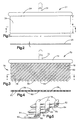
- a continuous, thin flat cross-sectioned, film-type gate design is used, as shown in Figs. 1 and 2.
- This type of gate design is good, but its rubber heating efficiency is reduced with increased injection speed because the shear heat generated by the faster injection speed is primarily absorbed in the gate wall or by the mold itself.
- It is an object of the present invention to provide an improved gate for directing rubber into an injection molding device being as defined in one or more of the appended claims and, as such, having the capability of being constructed to accomplish one or more of the following subsidiary objects.
- a lattice gate for injection molding of rubber in accordance with the invention is defined in claim 1.
- the separate intersecting flow channels of the gate intersect at an angle of about 60° to about 140° and preferably about 90° to about 120° with respect to each other.
- the gate includes: a lattice gate sprue plate having a flat inner surface with an inlet end and an outlet end, and a plurality of separate flow channels extending parallel to each other and disposed at an angle of about 30° to about 70° with respect to a centerline extending through the lattice gate sprue plate from the inlet end to the outlet end; a lattice gate plate having a flat inner surface with an inlet end and an outlet end, and a plurality of separate flow channels extending parallel to each other at an angle of about 30° to about 70° with respect to a centerline extending through the lattice gate plate from the inlet end to the outlet end; and the flat inner surface of the lattice gate sprue plate being abutted against the flat inner surface of the lattice gate plate.
- the separate flow channels in the lattice gate plate intersect the separate flow channels in the lattice gate sprue plate whereby the rubber streams flowing through the separate flow channels in the lattice gate plate and the lattice gate sprue plate mix both physically and thermally and generate more shear heating at the intersections of the separate flow channels.
- the lattice gate sprue plate has a sprue inlet bore extending through the lattice gate plate near the inlet end; and the lattice gate plate has a sprue inlet counterbore extending into the lattice gate plate near the inlet end and an elongated distribution channel extending across the lattice gate plate and connected to the sprue inlet counterbore and to the plurality of separate flow channels extending through the lattice gate plate and the lattice gate sprue plate from the elongated distribution channel to the outlet ends.
- a process for injecting a stream of rubber into an injection molding device comprising the steps of: directing the stream of rubber from the sprue channel into an elongated distribution channel; directing the a stream of rubber from the elongated distribution channel into a plurality of separate, intersecting flow channels connected at one end to the elongated distribution channel; thermally mixing rubber flowing through the separate flow channels at the intersection of the separate flow channels; and directing the rubber exiting the intersecting flow channels into a mold cavity.
- the process includes the step of directing the rubber into a plurality of separate, intersecting flow channels wherein the separate intersecting flow channels intersect so that the flat surface of the flow channels contact each other.
- the lattice gate can have a ring design to inject rubber into a circular, annulus-shaped mold having intersecting flow channels.
- FIG. 13 there is shown a schematic illustration of a typical injection molding machine 10 in accordance with the invention.
- the injection molding machine 10 includes an elongated barrel 12 into which rubber or a rubber compound is introduced.
- the rubber is driven through the barrel 12 by a rotating screw conveyor or a reciprocating ram or piston 18 disposed in the barrel 12, as is conventionally done in the prior art injection molding machines.
- the rubber moves through a gate system 20 to form a corresponding gate shaped portion of rubber.
- a gate shaped portion of rubber 21 corresponding to the shape of a conventional flat gate system.
- the rubber exiting the gate system 20 then flows into the mold cavity 28 of a mold 19.
- the present invention is primarily related to the design of a lattice gate system 30 for increasing the rubber to rubber contact through the gate system resulting in improved mixing and temperature uniformity of the rubber in the gate section, as compared to the prior art flat gate section 21.
- a 275-ton injection molding machine from Engel Corporation of Austria is suitable for use in the present invention.
- a continuous flat gate shaped portion 21 of rubber as illustrated in Figs. 1 and 2 and which corresponds to the internal flow passage through a prior art flat gate system (not shown), includes a sprue 22, a distribution runner 24 and a flat gate section 26.
- the flat gate section has a thickness 't' of about 0.012, a width 'w' of about 5.0 inches and a length '1' of about 1.25 inches.
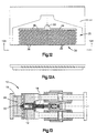
- An improved lattice gate system 30 as generally illustrated in Fig. 12, incorporates a sprue channel 32, a distribution channel 34 and a lattice shaped gate section 35 of intersecting rubber flow channels 36 and 38 which force the rubber flowing through the lattice gate system to be continuously mixed at the intersections of the flow channels for improved thermal distribution.
- the lattice gate system 30 uses a multiplicity of "static mixers", i.e., at each intersection of the two rubber flow channels 36 and 38, in a continuous array to thermally mix the rubber in the lattice shaped gate section 35 just prior to entering the mold cavity 28 of the injection molding machine.
- the lattice gate system 30 is used to direct the rubber flow from the downstream end 16 of a barrel 12 of an injection molding machine into the mold cavity 28.
- the lattice gate system 30 is located in the mold. However, it is within the terms of the invention to locate the lattice gate system 30 outside of the mold.
- Figs. 6-11 there is illustrated the components of the lattice gate system 30, i.e., the lattice gate sprue plate 40 and the lattice gate plate 42.
- Fig. 6 there is illustrated a plan view of the inner surface 44 of lattice gate sprue plate 40.
- the sprue plate 40 includes a sprue bore 46 which extends from the outer surface 48 to the inner surface 44.
- a plurality of flow channels 36 which are formed into the inner surface of plate 40, as shown in Figs.
- a sprue inlet counterbore 62 that extends into the inner surface 56 is positioned between the inlet end 58 and the outlet end 60 of the lattice gate plate 42.
- the sprue inlet counterbore 62 is in flow communication with an elongated distribution channel 64 extending partially across the length of lattice gate plate 42 and in parallel relation to the outlet end 60.
- a plurality of flow channels 66 which are formed into the inner surface of lattice gate plate 42, as shown in Figs.
- the flow channels 66 are preferably formed with a semi-circular cross-section.
- the flow channels 66 with any desired cross-sections such as for example, rectangular, triangular, or elliptical, as desired.
- FIGs. 12 and 12A there is shown the lattice gate system 30 with the flat inner surface 44 of the lattice gate sprue plate 40 abutted against the flat inner surface 56 of lattice gate plate 42 and secured thereto by conventional means such as bolting one to the other.
- the sprue bore 46 and the sprue inlet counterbore 62 intersect to form sprue channel 32.
- the flat inner surface 44 of sprue plate 40 abuts against elongated distribution channel 64 to form distribution channel 34.
- the distribution channel 34 is in fluid communication with the flow channels 36 and 38 that intersect to form the lattice shaped gate section 35.
- An important aspect of the invention relates to the configuration of the distribution channel 34 after the lattice gate system 30 is assembled. That is, the flow channels 36 and 38 are disposed to intersect each other at an angle of about 60° to about 140° with respect to each other and preferably about 90° to about 120° with respect to each other. Also, portions of the flow channels 36 and 38 of the lattice gate sprue plate 40 and the lattice gate plate 42, respectively, are partially formed, typically with a half circle or elliptical shape, resulting from being abutted against the flat surface of the opposing, either the lattice gate plate 42 or the lattice gate sprue plate 40. The remaining portions of the flow channels 36 and 38 are formed at the intersection of the flow channels 36 and 38 and are illustrated in Fig. 12A as having an elliptical shape.
- the process includes the steps of directing rubber or a rubber compound into the inlet 14 of barrel 12 of the injection molding machine 10.
- the rubber is forced down the barrel 12 by conventional means, such as with a ram or screw injector device 18, as is conventionally known in the art.
- the rubber is directed through a sprue channel 32 formed in the lattice shaped gate section 35 and then into the elongated distribution channel 34.
- the rubber is directed from the elongated distribution channel 34 into the plurality of separate, intersecting flow channels 36 and 38 connected at the upstream ends to the elongated distribution channel 34 and at the opposite downstream ends to the mold cavity 28 of the injection molding machine 10.
- the flow of the rubber through the lattice shaped gate section 35 forms the lattice gate shaped portion 70 of rubber which includes a sprue 72, a distribution runner 74 and a lattice gate section 76 of intersecting parallel rubber streams 78 and 80.
- the streams 78 and 80 of rubber flow are forced through the separate intersecting flow channels 36 and 38, the rubber heats up and thermally mixes at each intersection of the separate flow channels, as illustrated in Fig. 5.
- the rubber flow streams 78 and 80 each have a cross section disposed with the flat inner surfaces 82 and 84 abutting against each other at the plurality of intersections
- the rubber flow streams form a differently shaped cross section, such as elliptical, at the intersection of the channels 36 and 38, as seen in Fig. 5.
- the rubber streams continue their flow from one end of the gate to the other, they pass through a series of intersections where the rubber is thermally mixed.
- An important aspect of present invention is that while the number of intersections and the shape of the intersections can vary depending on the specific application, the rubber streams are thermally mixed more and to a higher temperature as the number of intersections through which the rubber streams flow increases.
- both the flat and lattice shaped gates have the same effective cross-sectional flow area. From the results discussed below, and illustrated in Figs. 14, 15, and 16, the blow point cure time for the lattice gate design of Fig. 3 decreased with increasing injection speed, with no adverse affects on part scorch, whereas the comparable flat gate design of Fig. 1, when subjected to similar conditions, exhibited part scorch.
- Porosity in the interior of rubber articles must be avoided. Porosity creates weak, spongy areas in the finished product which can be the locations at which the article blows or fails in service. The finished article also can have undesirable bulges from the porosity which cause parts to be scrapped. Blowing is caused when the internal pressure of volatiles in the rubber compound exceed the strength of the material at the time of demolding or removal from the mold. Porosity results when the rubber article is demolded prior to curing beyond the part's blow point.
- the cure time is determined or limited by the point of least cure in an article. The article will "blow” or have porosity when the cure time is less than the "blow point” cure time.
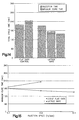
- Figs. 14, 15, and 16 there is shown the results of increasing the injection speed through a flat gate design as compared with a comparable, or substantially equivalent lattice gate design having substantially the same effective cross-sectional flow area.
- Fig. 14 there is illustrated a chart comparing the total cycle time, i.e., the injection time plus the cure time, in seconds between a prior art flat gate and comparable lattice gate design of the present invention.
- the chart of Fig. 14 indicates that as the injection time decreases for the flat gate, the minimum cure time increases. Conversely, when the injection time decreases for the lattice gate design, the cure time decreases.
- Fig. 14 graphically show a very significant advantage of the lattice gate design. That is, a decrease in injection time for the lattice gate design results in a decrease in the minimum cure time, the largest portion of the total cycle time.
- the minimum cure time is defined as the least cure time which exceeds the blow point at the point of least cure in the article being molded.
- Fig. 15 is a chart using the same data as Fig. 14 that also shows a decrease in the minimum cure time as time for specific injection speed increases with the lattice gate, as opposed to the flat gate which has a significantly higher minimum cure time blow point for the same injection speed.
- the cure time for the flat gate design depends on the injection speed. That is, as the injection speed increases beyond 2,5 mm per second (0.1 inches per second), the minimum cure time also increases.
- the injection speed is inversely proportional to the minimum cure time, i.e., as the injection speed increases, the minimum cure time decreases.
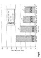
- Fig. 16 there are illustrated bar graphs comparing the total cycle time, i.e., the injection time plus the hold time plus the minimum cure time for substantially equivalent flat and lattice gate designs having substantially the same effective cross-sectional flow area.
- the hold time is the time that the part is held at high pressure before the injector is retracted for the next screw and injection refill cycle.
- a lattice gate built along the concepts of the lattice gates described herein before has a ring shape for injecting rubber into a circular, annulus-shaped mold (not shown).
- the top lattice gate ring 90 as illustrated in Fig. 17, has an interior surface 92 with a plurality of sprue holes 94 disposed around the circular distribution channel 96.
- the channel 96 is intersected by a plurality of flow channels 98 which extend around the peripheral edge of lattice gate ring 90.
- Each of the grooves which form flow channels 98 is disposed to intersect a centerline 100 at an angle "d" of about 30° to about 70° and preferably at an angle of about 45° to about 60°.
- the channels 98 as shown, have an angle "d" of about 45° and are at 1° spacing to provide 360 channels about the circumference of the ring 90. While 360 channels 98 are illustrated, it is within the terms of the invention to use any desired number of channels.
- the bottom plate 102 has an interior surface 104 with a circular distribution channel 106.
- a plurality of channels 108 extend around the outer circumference of the bottom lattice gate ring plate 102 at an angle "e" with respect to centerline 110 where "e” corresponds to the angle "d” in the top lattice gate ring plate 90 with the same angle as selected for the channels 98.
- the channels 108 are illustrated as being disposed 1° apart so that 360 channels 108 extend around the circumference of the bottom plate 102.
- Fig. 19 illustrates a section of a lattice gate ring 112 where the interior surface 92 of the top lattic gate ring plate is abutted against the interior surface 104 of the bottom lattice gate ring plate 102 so that channels 98 and 108 intersect each other.
- the stream of rubber is forced through the sprue bores 94 into the distribution channel formed between channels 96 and 106 and then into the intersecting channels 98 and 108 so that the rubber is continuously mixed at the intersections of the flow channels for improved thermal distribution as the rubber is directed into the mold cavity.
- the second embodiment, as illustrated in Fig. 19, of the lattice gate ring 112 is basically operated with the same principles as the lattice gate system 30 described before and generally illustrated in Fig. 12.
- the improved lattice gate design directs rubber into an injection molding device whereby the rubber can be physically mixed within the gate to decrease the injection time while simultaneously reducing the curing time for a rubber part formed in a mold cavity supplied by the lattice gate.
Landscapes
- Engineering & Computer Science (AREA)
- Manufacturing & Machinery (AREA)
- Mechanical Engineering (AREA)
- Injection Moulding Of Plastics Or The Like (AREA)
- Moulds For Moulding Plastics Or The Like (AREA)
- Heating, Cooling, Or Curing Plastics Or The Like In General (AREA)
- Compositions Of Macromolecular Compounds (AREA)
- Materials For Photolithography (AREA)
- Cold Cathode And The Manufacture (AREA)
Claims (19)
- Entrée en treillis (30) pour le moulage de caoutchouc par injection dans une cavité de moule (28) d'un dispositif (10) de moulage par injection, l'entrée en treillis (30) étant caractérisée par:un canal de distribution allongé (64) pour la réception d'un courant du caoutchouc;un premier ensemble de canaux d'écoulement espacés (36) reliés à une de leurs extrémités au canal de distribution allongé (64) et à leur extrémité opposée à la cavité de moule (28); etun second ensemble de canaux d'écoulement espacés (66) reliés à une de leurs extrémités au canal de distribution allongé (64) et à leur extrémité opposée à la cavité de moule (28), les premier et second ensembles de canaux d'écoulement espacés (36, 66) étant disposés pour se couper l'un l'autre, si bien que l'on obtient un mélange par voie thermique du courant de caoutchouc à travers chacun des premier et second ensembles de canaux d'écoulement espacés (36, 66).
- Entrée en treillis selon la revendication 1, caractérisée en outre en ce que les premier et second ensembles de canaux d'écoulement espacés (36, 66) possèdent une forme choisie parmi le groupe comprenant une section transversale elliptique, une section transversale semi-circulaire, une section transversale rectangulaire et une section transversale triangulaire.
- Entrée en treillis selon la revendication 2, caractérisée en outre en ce que les premier et second ensembles de canaux d'écoulement espacés (36, 66) forment à l'intersection des canaux d'écoulement, une section transversale elliptique.
- Système d'entrée en treillis selon la revendication 1, caractérisé en outre en ce que les premier et second ensembles de canaux d'écoulement espacés (36, 66) se coupent l'un l'autre en formant un angle d'environ 60° à environ 140° l'un par rapport à l'autre.
- Entrée en treillis selon la revendication 4, caractérisée en outre en ce que les premier et second ensembles de canaux d'écoulement espacés (36, 66) se coupent l'un l'autre de préférence en formant un angle d'environ 90° à environ 120° l'un par rapport à l'autre.
- Entrée en treillis selon la revendication 1, caractérisée en outre en ce que les canaux d'écoulement espacés (36) du premier ensemble sont disposés respectivement en relation parallèle l'un par rapport à l'autre et les canaux d'écoulement espacés (66) du second ensemble sont disposés respectivement en relation parallèle l'un à l'autre.
- Système d'entrée en treillis selon la revendication 1, caractérisé en outre par un canal de carotte (32) pour diriger du caoutchouc dans le canal de distribution allongé (64).
- Entrée en treillis selon la revendication 1, caractérisée en outre par:une plaque de carotte d'entrée en treillis (40) possédant une surface interne plate (44), comprenant une extrémité d'entrée (52) et une extrémité de sortie (54), les canaux d'écoulement espacés (36) du premier ensemble s'étendant parallèlement l'un à l'autre e formant un angle d'environ 30° à environ 70° par rapport à une ligne médiane (50) s'étendant à travers la plaque de carotte d'entrée en treillis (40) depuis l'extrémité d'entrée (52) jusqu'à l'extrémité de sortie (54);une plaque d'entrée en treillis (42) possédant une surface interne plate (56), comprenant une extrémité d'entrée (58) et une extrémité de sortie (60), les canaux d'écoulement espacés (66) du second ensemble s'étendant parallèlement l'un à l'autre en formant un angle d'environ 30° à environ 70° par rapport à une ligne médiane (68) s'étendant à travers la plaque d'entrée en treillis (42) depuis l'extrémité d'entrée (58) jusqu'à l'extrémité de sortie (60); etla surface interne plate (44) de la plaque de carotte d'entrée en treillis (40) venant buter contre la surface interne plate (56) de la plaque d'entrée en treillis (42), si bien que les canaux d'écoulement espacés (36) du premier ensemble dans la plaque de carotte d'entrée en treillis (40) coupe le second ensemble de canaux d'écoulement espacés (66) dans la plaque d'entrée en treillis (42).
- Entrée en treillis selon la revendication 8, caractérisée en outre en ce que les canaux espacés (36) du premier ensemble dans la plaque de carotte d'entrée en treillis (40) et les canaux d'écoulement espacés (66) second ensemble dans la plaque d'entrée en treillis (42) forment le même angle par rapport à la ligne centrale traversant la plaque de carotte d'entrée (40) et la plaque d'entrée (42) respectives.
- Entrée en treillis selon la revendication 9, caractérisée en outre par le fait que:la plaque de carotte d'entrée en treillis (40) possède un alésage d'entrée de carotte (46) s'étendant à travers la plaque d'entrée en treillis (42) à proximité de l'extrémité d'entrée (52); etla plaque d'entrée en treillis (42) possède un contre-alésage (62) d'entrée de carotte s'étendant dans la plaque de carotte d'entrée en treillis (42) à proximité de l'extrémité d'entrée (58) et un canal de distribution allongé (64) s'étendant à travers la plaque d'entrée en treillis (42) et reliée au contre-alésage d'entrée de carotte (62), ainsi qu'aux ensembles de canaux séparés (66, 68), lesdits canaux d'écoulement (66, 68) s'étendant à travers la plaque d'entrée en treillis (42) et à travers la plaque de carotte d'entrée en treillis (40) depuis le canal de distribution allongé (64) jusqu'aux extrémités de sortie de la plaque d'entrée (42) et de la plaque de carotte d'entrée (40) respectives.
- Procédé pour le moulage de caoutchouc par injection caractérisée par les étapes consistant à:diriger un courant de caoutchouc dans un canal de distribution allongé (64);diriger le courant de caoutchouc depuis le canal de distribution allongé (64) jusque dans des premier et second ensembles de canaux d'écoulement espacés (36, 66) qui s'entrecoupent, reliés à une de leurs extrémités au canal de distribution allongé (64);mélanger par voie thermique le courant de caoutchouc s'écoulant à travers les premier et second canaux d'écoulement espacés (36, 66) à l'intersection des premier et second canaux d'écoulement espacés (36, 66); etdiriger le caoutchouc quittant les premier et second canaux d'écoulement espacés (36, 66) dans une cavité de moule.
- Procédé selon la revendication 11, caractérisé en outre en ce que l'étape consistant à diriger les courants de caoutchouc dans les premier et second ensembles de canaux d'écoulement espacés (36, 66) qui s'entrecoupent, englobe l'étape d'intersection des courants de caoutchouc s'écoulant à travers les premier et second ensembles de canaux d'écoulement (36, 66) de telle sorte qu'une surface plate des courants de caoutchouc s'écoulant à travers les premiers ensembles de canaux d'écoulement (36) vienne buter contre la surface plate des courants de caoutchouc s'écoulant à travers les seconds ensembles de canaux d'écoulement (66).
- Procédé selon la revendication 12, caractérisé en outre par l'étape consistant à diriger les courants de caoutchouc dans les ensembles des premier et second canaux d'écoulement espacés (36, 66) qui s'entrecoupent en formant un angle d'environ 60° à environ 140° l'un par rapport à l'autre.
- Procédé selon la revendication 13, caractérisé en outre par l'étape consistant à diriger les courants de caoutchouc dans les ensembles des premier et second canaux d'écoulement espacés (36, 66) qui s'entrecoupent en formant un angle d'environ 80° à environ 120° l'un par rapport à l'autre.
- Entrée en treillis pour le moulage de caoutchouc par injection dans une cavité de moule de forme annulaire d'un dispositif de moulage par injection, l'entrée en treillis étant caractérisée par:un canal de distribution circulaire (106) pour la réception d'un courant du caoutchouc;un premier ensemble de canaux d'écoulement espacés (98) reliés à une de leurs extrémités au canal de distribution circulaire (106) et à leur extrémité opposée à la cavité de moule de forme annulaire; etun second ensemble de canaux d'écoulement espacés (108) reliés à une de leurs extrémités au canal de distribution circulaire (106) et à leur extrémité opposée à la cavité de moule de forme annulaire, les premier et second ensembles de canaux d'écoulement espacés (98, 108) étant disposés pour se couper l'un l'autre, de telle sorte que l'on obtient un mélange par voie thermique du caoutchouc traversant chacun des premier et second ensembles de canaux d'écoulement espacés.
- Système d'entrée en treillis selon la revendication 15, caractérisé en outre en ce que les premiers et second ensembles de canaux d'écoulement espacés (98, 108) se coupent l'un l'autre en formant un angle d'environ 60° à environ 140° l'un par rapport à l'autre.
- Procédé pour le moulage de caoutchouc par injection caractérisé par le fait qu'il comprend les étapes consistant à:diriger un courant de caoutchouc dans un canal de distribution circulaire (106);diriger le courant de caoutchouc depuis le canal de distribution circulaire (106) jusque dans des premier et second ensembles de canaux d'écoulement espacés (98, 108) qui s'entrecoupent, reliés à une de leurs extrémités au canal de distribution circulaire (106);mélanger par voie thermique le courant de caoutchouc s'écoulant à travers les premier et second canaux d'écoulement espacés (98, 108) à l'intersection des premier et second canaux d'écoulement espacés (98, 108); etdiriger le caoutchouc quittant les premier et second canaux d'écoulement espacés (98, 108) dans une cavité de moule de forme annulaire.
- Procédé selon la revendication 17, caractérisé en outre en ce que l'étape consistant à diriger le courant de caoutchouc dans les premier et second ensembles de canaux d'écoulement espacés (98, 108) qui s'entrecoupent, englobe l'étape d'intersection des courants de caoutchouc s'écoulant à travers les premier et second ensembles de canaux d'écoulement (98, 108) de telle sorte qu'une surface plate des courants de caoutchouc s'écoulant à travers le premier ensemble de canaux d'écoulement (98) vienne buter contre la surface plate des courants de caoutchouc s'écoulant à travers le second ensemble de canaux d'écoulement (108).
- Procédé selon la revendication 12, caractérisé en outre par l'étape consistant à diriger les courants de caoutchouc dans les ensembles des premier et second canaux d'écoulement espacés (98, 108) qui s'entrecoupent en formant un angle d'environ 60° à environ 140° l'un par rapport à l'autre.
Applications Claiming Priority (1)
| Application Number | Priority Date | Filing Date | Title |
|---|---|---|---|
| PCT/US1997/009916 WO1998056559A1 (fr) | 1997-06-09 | 1997-06-09 | Entree en treillis pour le moulage par injection de melanges de caoutchouc |
Publications (2)
| Publication Number | Publication Date |
|---|---|
| EP1009611A1 EP1009611A1 (fr) | 2000-06-21 |
| EP1009611B1 true EP1009611B1 (fr) | 2001-11-07 |
Family
ID=22261046
Family Applications (1)
| Application Number | Title | Priority Date | Filing Date |
|---|---|---|---|
| EP97928901A Expired - Lifetime EP1009611B1 (fr) | 1997-06-09 | 1997-06-09 | Entree en treillis pour le moulage par injection de melanges de caoutchouc |
Country Status (7)
| Country | Link |
|---|---|
| EP (1) | EP1009611B1 (fr) |
| JP (1) | JP2002503164A (fr) |
| AT (1) | ATE208258T1 (fr) |
| AU (1) | AU3305297A (fr) |
| CA (1) | CA2293636A1 (fr) |
| DE (1) | DE69708161T2 (fr) |
| WO (1) | WO1998056559A1 (fr) |
Families Citing this family (5)
| Publication number | Priority date | Publication date | Assignee | Title |
|---|---|---|---|---|
| US6607688B1 (en) | 2000-09-08 | 2003-08-19 | The Goodyear Tire & Rubber Company | Lattice gate for drop gate injection molding |
| US6387313B1 (en) * | 1999-12-15 | 2002-05-14 | The Goodyear Tire & Rubber Company | Gate for injection molding rubber compounds |
| CA2354319A1 (fr) | 2000-09-08 | 2002-03-08 | The Goodyear Tire & Rubber Company | Canal secondaire d'injection pour moulage par injection |
| KR101536399B1 (ko) * | 2013-05-03 | 2015-07-14 | 한국기계연구원 | 인 몰드 코팅장치 |
| JP2020121479A (ja) * | 2019-01-30 | 2020-08-13 | オリンパス株式会社 | 射出成形金型 |
Family Cites Families (3)
| Publication number | Priority date | Publication date | Assignee | Title |
|---|---|---|---|---|
| US2426651A (en) * | 1946-03-04 | 1947-09-02 | French Oil Mill Machinery | Injection molding |
| GB1570853A (en) * | 1975-02-19 | 1980-07-09 | Pirelli | Mehtod and apparatus for the injection moulding of pneumatic tyres |
| US3989434A (en) * | 1975-10-29 | 1976-11-02 | Mcdowell-Wellman Engineering Company | Blending and molding means |
-
1997
- 1997-06-09 WO PCT/US1997/009916 patent/WO1998056559A1/fr not_active Ceased
- 1997-06-09 CA CA002293636A patent/CA2293636A1/fr not_active Abandoned
- 1997-06-09 AU AU33052/97A patent/AU3305297A/en not_active Abandoned
- 1997-06-09 JP JP50232999A patent/JP2002503164A/ja active Pending
- 1997-06-09 EP EP97928901A patent/EP1009611B1/fr not_active Expired - Lifetime
- 1997-06-09 DE DE69708161T patent/DE69708161T2/de not_active Expired - Fee Related
- 1997-06-09 AT AT97928901T patent/ATE208258T1/de not_active IP Right Cessation
Also Published As
| Publication number | Publication date |
|---|---|
| AU3305297A (en) | 1998-12-30 |
| EP1009611A1 (fr) | 2000-06-21 |
| JP2002503164A (ja) | 2002-01-29 |
| CA2293636A1 (fr) | 1998-12-17 |
| WO1998056559A1 (fr) | 1998-12-17 |
| DE69708161D1 (de) | 2001-12-13 |
| DE69708161T2 (de) | 2002-06-20 |
| ATE208258T1 (de) | 2001-11-15 |
Similar Documents
| Publication | Publication Date | Title |
|---|---|---|
| US4238181A (en) | Method and apparatus for runnerless injection-compression molding thermosetting materials | |
| US3507010A (en) | Continuous molding of thermoplastic materials | |
| US3590109A (en) | Continuous molding of thermoplastic materials | |
| US8211349B2 (en) | Machine for injecting a heat curable material, in particular for rubber vulcanisation, and corresponding method for achieving same | |
| CA2270015A1 (fr) | Dispositif d'etalonnage avec au moins une matrice d'etalonnage | |
| EP0013118B1 (fr) | Buse d'injection et machine d'injection pour mouler des matières thermodurcissables | |
| US4309379A (en) | Method and apparatus for runnerless injection-compression molding thermosetting materials | |
| US4459250A (en) | Process and apparatus of extrusion molding rubbers and thermal cross-linking synthetic resins | |
| US6379603B1 (en) | Lattice gate for injection molding of rubber compounds | |
| US3194868A (en) | Process and apparatus for molding thermosetting material | |
| WO1998056559A1 (fr) | Entree en treillis pour le moulage par injection de melanges de caoutchouc | |
| US6387313B1 (en) | Gate for injection molding rubber compounds | |
| US4501549A (en) | Injection mold with replacable insert in mold cavity outlet opening | |
| JP2002120257A (ja) | 射出成形用構成部品とゴム成形品製造方法 | |
| WO2016084134A1 (fr) | Procédé de moulage multipièce par injection et moule | |
| US5006059A (en) | Mold for injection molding of toothed power transmission belt | |
| EP0013119B1 (fr) | Dispositif pour mouler sans carotte des matières thermodurcissables par injection-compression | |
| JPH0538738A (ja) | 可塑化部を分離したタイプの成形機 | |
| MXPA99010895A (en) | Lattice gate for injection molding of rubber compounds | |
| US20030206992A1 (en) | Lattice gate for drop gate injection molding | |
| JPS5593437A (en) | Injection molding process with thermo-linked reaction of rubber and synthetic resin | |
| Fancy et al. | Elastomer processing | |
| KR20010013484A (ko) | 래티스 게이트 및 고무를 사출 성형하는 방법 | |
| RU2037419C1 (ru) | Способ изготовления изделий из полимерных термореактивных материалов | |
| US12377587B2 (en) | Shut-off nozzle for injection molding |
Legal Events
| Date | Code | Title | Description |
|---|---|---|---|
| PUAI | Public reference made under article 153(3) epc to a published international application that has entered the european phase |
Free format text: ORIGINAL CODE: 0009012 |
|
| 17P | Request for examination filed |
Effective date: 20000110 |
|
| AK | Designated contracting states |
Kind code of ref document: A1 Designated state(s): AT CH DE ES FR GB IT LI NL |
|
| GRAG | Despatch of communication of intention to grant |
Free format text: ORIGINAL CODE: EPIDOS AGRA |
|
| 17Q | First examination report despatched |
Effective date: 20000911 |
|
| GRAG | Despatch of communication of intention to grant |
Free format text: ORIGINAL CODE: EPIDOS AGRA |
|
| GRAH | Despatch of communication of intention to grant a patent |
Free format text: ORIGINAL CODE: EPIDOS IGRA |
|
| GRAH | Despatch of communication of intention to grant a patent |
Free format text: ORIGINAL CODE: EPIDOS IGRA |
|
| GRAA | (expected) grant |
Free format text: ORIGINAL CODE: 0009210 |
|
| AK | Designated contracting states |
Kind code of ref document: B1 Designated state(s): AT CH DE ES FR GB IT LI NL |
|
| PG25 | Lapsed in a contracting state [announced via postgrant information from national office to epo] |
Ref country code: NL Free format text: LAPSE BECAUSE OF FAILURE TO SUBMIT A TRANSLATION OF THE DESCRIPTION OR TO PAY THE FEE WITHIN THE PRESCRIBED TIME-LIMIT Effective date: 20011107 Ref country code: LI Free format text: LAPSE BECAUSE OF FAILURE TO SUBMIT A TRANSLATION OF THE DESCRIPTION OR TO PAY THE FEE WITHIN THE PRESCRIBED TIME-LIMIT Effective date: 20011107 Ref country code: CH Free format text: LAPSE BECAUSE OF FAILURE TO SUBMIT A TRANSLATION OF THE DESCRIPTION OR TO PAY THE FEE WITHIN THE PRESCRIBED TIME-LIMIT Effective date: 20011107 Ref country code: AT Free format text: LAPSE BECAUSE OF FAILURE TO SUBMIT A TRANSLATION OF THE DESCRIPTION OR TO PAY THE FEE WITHIN THE PRESCRIBED TIME-LIMIT Effective date: 20011107 |
|
| REF | Corresponds to: |
Ref document number: 208258 Country of ref document: AT Date of ref document: 20011115 Kind code of ref document: T |
|
| REG | Reference to a national code |
Ref country code: CH Ref legal event code: EP |
|
| REF | Corresponds to: |
Ref document number: 69708161 Country of ref document: DE Date of ref document: 20011213 |
|
| REG | Reference to a national code |
Ref country code: GB Ref legal event code: IF02 |
|
| ET | Fr: translation filed | ||
| NLV1 | Nl: lapsed or annulled due to failure to fulfill the requirements of art. 29p and 29m of the patents act | ||
| REG | Reference to a national code |
Ref country code: CH Ref legal event code: PL |
|
| PG25 | Lapsed in a contracting state [announced via postgrant information from national office to epo] |
Ref country code: ES Free format text: LAPSE BECAUSE OF FAILURE TO SUBMIT A TRANSLATION OF THE DESCRIPTION OR TO PAY THE FEE WITHIN THE PRESCRIBED TIME-LIMIT Effective date: 20020530 |
|
| PLBE | No opposition filed within time limit |
Free format text: ORIGINAL CODE: 0009261 |
|
| STAA | Information on the status of an ep patent application or granted ep patent |
Free format text: STATUS: NO OPPOSITION FILED WITHIN TIME LIMIT |
|
| 26N | No opposition filed | ||
| PGFP | Annual fee paid to national office [announced via postgrant information from national office to epo] |
Ref country code: GB Payment date: 20060505 Year of fee payment: 10 |
|
| PGFP | Annual fee paid to national office [announced via postgrant information from national office to epo] |
Ref country code: FR Payment date: 20060605 Year of fee payment: 10 |
|
| PGFP | Annual fee paid to national office [announced via postgrant information from national office to epo] |
Ref country code: DE Payment date: 20060630 Year of fee payment: 10 |
|
| PGFP | Annual fee paid to national office [announced via postgrant information from national office to epo] |
Ref country code: IT Payment date: 20070620 Year of fee payment: 11 |
|
| GBPC | Gb: european patent ceased through non-payment of renewal fee |
Effective date: 20070609 |
|
| REG | Reference to a national code |
Ref country code: FR Ref legal event code: ST Effective date: 20080229 |
|
| PG25 | Lapsed in a contracting state [announced via postgrant information from national office to epo] |
Ref country code: DE Free format text: LAPSE BECAUSE OF NON-PAYMENT OF DUE FEES Effective date: 20080101 |
|
| PG25 | Lapsed in a contracting state [announced via postgrant information from national office to epo] |
Ref country code: GB Free format text: LAPSE BECAUSE OF NON-PAYMENT OF DUE FEES Effective date: 20070609 |
|
| PG25 | Lapsed in a contracting state [announced via postgrant information from national office to epo] |
Ref country code: FR Free format text: LAPSE BECAUSE OF NON-PAYMENT OF DUE FEES Effective date: 20070702 |
|
| PG25 | Lapsed in a contracting state [announced via postgrant information from national office to epo] |
Ref country code: IT Free format text: LAPSE BECAUSE OF NON-PAYMENT OF DUE FEES Effective date: 20080609 |