EP1009904B1 - Aufrollvorrichtung für rollos - Google Patents
Aufrollvorrichtung für rollos Download PDFInfo
- Publication number
- EP1009904B1 EP1009904B1 EP98929252A EP98929252A EP1009904B1 EP 1009904 B1 EP1009904 B1 EP 1009904B1 EP 98929252 A EP98929252 A EP 98929252A EP 98929252 A EP98929252 A EP 98929252A EP 1009904 B1 EP1009904 B1 EP 1009904B1
- Authority
- EP
- European Patent Office
- Prior art keywords
- nut
- winding mechanism
- shoulder
- friction
- rod
- Prior art date
- Legal status (The legal status is an assumption and is not a legal conclusion. Google has not performed a legal analysis and makes no representation as to the accuracy of the status listed.)
- Expired - Lifetime
Links
- 230000007246 mechanism Effects 0.000 title claims description 20
- 238000004804 winding Methods 0.000 title claims description 19
- 230000006835 compression Effects 0.000 claims description 23
- 238000007906 compression Methods 0.000 claims description 23
- 230000001419 dependent effect Effects 0.000 claims description 5
- 238000010276 construction Methods 0.000 description 8
- 239000000243 solution Substances 0.000 description 4
- 230000006870 function Effects 0.000 description 3
- 230000001133 acceleration Effects 0.000 description 2
- 230000009471 action Effects 0.000 description 2
- 230000008901 benefit Effects 0.000 description 2
- 239000000463 material Substances 0.000 description 2
- 238000012856 packing Methods 0.000 description 2
- 238000010009 beating Methods 0.000 description 1
- 230000008859 change Effects 0.000 description 1
- 230000000694 effects Effects 0.000 description 1
- 239000004744 fabric Substances 0.000 description 1
- 239000011888 foil Substances 0.000 description 1
- 239000002783 friction material Substances 0.000 description 1
- 238000001746 injection moulding Methods 0.000 description 1
- 230000003446 memory effect Effects 0.000 description 1
- 239000004810 polytetrafluoroethylene Substances 0.000 description 1
- 229920001343 polytetrafluoroethylene Polymers 0.000 description 1
- 238000002360 preparation method Methods 0.000 description 1
- 230000003134 recirculating effect Effects 0.000 description 1
- 230000002040 relaxant effect Effects 0.000 description 1
Images


Classifications
-
- E—FIXED CONSTRUCTIONS
- E06—DOORS, WINDOWS, SHUTTERS, OR ROLLER BLINDS IN GENERAL; LADDERS
- E06B—FIXED OR MOVABLE CLOSURES FOR OPENINGS IN BUILDINGS, VEHICLES, FENCES OR LIKE ENCLOSURES IN GENERAL, e.g. DOORS, WINDOWS, BLINDS, GATES
- E06B9/00—Screening or protective devices for wall or similar openings, with or without operating or securing mechanisms; Closures of similar construction
- E06B9/24—Screens or other constructions affording protection against light, especially against sunshine; Similar screens for privacy or appearance; Slat blinds
- E06B9/40—Roller blinds
- E06B9/42—Parts or details of roller blinds, e.g. suspension devices, blind boxes
- E06B9/44—Rollers therefor; Fastening roller blinds to rollers
-
- E—FIXED CONSTRUCTIONS
- E06—DOORS, WINDOWS, SHUTTERS, OR ROLLER BLINDS IN GENERAL; LADDERS
- E06B—FIXED OR MOVABLE CLOSURES FOR OPENINGS IN BUILDINGS, VEHICLES, FENCES OR LIKE ENCLOSURES IN GENERAL, e.g. DOORS, WINDOWS, BLINDS, GATES
- E06B9/00—Screening or protective devices for wall or similar openings, with or without operating or securing mechanisms; Closures of similar construction
- E06B9/56—Operating, guiding or securing devices or arrangements for roll-type closures; Spring drums; Tape drums; Counterweighting arrangements therefor
- E06B9/80—Safety measures against dropping or unauthorised opening; Braking or immobilising devices; Devices for limiting unrolling
- E06B2009/807—Brakes preventing fast screen movement
Definitions
- the invention relates to a winding mechanism for roller blinds which are rolled onto a tube, of the kind in which a stationary rod inside the tube is held by an external fixture, one end of the tube being rotatably supported on the rod by means of a bearing sleeve, and in which a rotational force is created between the rod and the tube.
- a spring is tensioned when the blind is pulled down, and a latching device blocks the roller blind at desired adjustments.
- the construction provides an advantageous characteristic, because the force of the spring is at its maximum when the tube has to carry the largest lenght of hanging blind.
- the latching device is freed by means of a sharp pull in the blind the roller blind is wound around the tube during a strong acceleration. When it has reached the top it has obtained the highest speed, and means have been provided to brake the bottom rail when it has been completely raised. It is important that the fully wound roller blind does not participate in the rotation, because this would relax the spring, so that the bottom rail would end dangling at an undefined height below the desired position.
- the bottom rail is frequently stopped by means of its dimensions or by means of a projection fitted to the bottom rail.
- the sharp braking is harmful, both for the roller blind and seams provided in it, and for the window frame which receives beatings from the projections. It is under all circumstances desirable that the spring has a minimum bias when the roller blind is in its uppermost position.
- the axial force may be provided either by means of a helical spring or by means of a piston which acts on a volume of air in a cylinder.
- One embodiment is particular in that the elastic force is provided by means of a piston which acts against a closed volume of air in a cylinder.
- any desired compression spring characteristic may be dynamically obtained, as it will have been noted that the greatest problem of braking occurs when the roller blind is fast rotating, whereas there is a need for sufficient spring force to obtain correct raising during slow rotation, where there is no stored energy due to the moment of inertia.
- An advantageous embodiment is particular in that the friction is established between the nut and the thread, the support of the compression spring on the nut, alternatively on the shoulder being reduced in friction.
- an axial ball bearing or similar bearing may be provided between the spring and one of its supports. This construction is equally well adapted for use with the air cylinder spring discussed above.
- a further embodiment is particular in that the helical compression spring is supported between a plug with a bearing journal and the nut.
- a further embodiment further develops this solution and is particular in that the threaded rod is taken through the plug and is fixed against rotation by means of a fixture independent of the clamping of the rod for the raising spring.
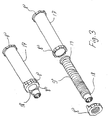
- a mechanism for a roller for a roller blind which is normally fitted inside a tube which fixed to a rotating bearing part 1.
- This mechanism consists in particular in a rod 2 around which is fitted a helical raising spring 3. This is fixed between the bearing part 1 and a fixing device 4 on the rod.
- the end of the rod 2 is available at the outside of the roller in the shape of a projection 5 which is held against rotation by means of a roller blind fixture which is not shown.
- the other part of the tube is provided with a plug - not shown - and a bearing journal which is free to rotate in a bearing in a second roller blind fitting.
- the direction of rotation is immaterial for its working principle, but for the sake of the description the present explanation defines that rotation of the tube and the bearing part 1 in the direction of the arrow causes a tensioning of the raising spring 3, i.e. the roller blind is pulled down.
- latching devices are fitted in the bearing part 1 which are released by pulling the roller blind and which do not influence the movement as long as the bearing part 1 rotates.
- the piston packing ring may be made in one piece with the piston rod by means of an injection molding process as shown in the figure, but it may also be made in the form of a separate elastomeric ring which is rolled over the end of the piston rod.
- the calibrated exhaust opening is in this case an axial groove which passes between the piston packing ring and the piston rod.
- a further embodiment according to claim 8 utilises the advantage that one friction-reducing location may be saved, because the spring 7 has been lengthened all the way to the bearing part 1, thereby surrounding the spring 3. This is shown schematically as the spring part 7a.
- the fixing device 4 has a reduced diameter.
Landscapes
- Engineering & Computer Science (AREA)
- Structural Engineering (AREA)
- Architecture (AREA)
- Civil Engineering (AREA)
- Operating, Guiding And Securing Of Roll- Type Closing Members (AREA)
- Blinds (AREA)
Claims (13)
- Wickeleinrichtung für Rollvorhänge, die auf einem Rohr (T) aufgewickelt sind, von der Bauart in welcher eine feste Stange (2) im Rohr (T) von einer äusseren Festhaltevorrichtung gehalten wird, eine Endes des Rohres auf der Stange drehbar mittels einer Lagerbüchse (1) gelagert, und worin eine Drehkraft zwischen der Stange und dem Rohr erzeugt wird, die Wickeleinrichtung eine feste, nicht-drehbare Gewindestange (9) umfassend, die mit einer Mutter, von dem Rohr (T) gedreht und dadurch seitwärts verschoben, zusammenwirkt, Mittel, womit eine Axialkraft an der Mutter angelegt wird, welche Kraft wenigstens während eine schnelle Rotation des Rohres in einer ersten Richtung wegen der Bewegung der Mutter gesteigert wird, und Bauteile, die eine kontrollierte Reibungskraft gegen die Drehung der Mutter (8) bewirken.
- Wickeleinrichtung für Rollvorhänge nach Anspruch 1,
dadurch gekennzeichnet, dass die Axialkraft mittels einer Schraubendruckfeder (7, 7a) erzeugt wird. - Wickeleinrichtung für Rollvorhänge nach Anspruch 1,
dadurch gekennzeichnet, dass die Axialkraft mittels eines Stempels, auf ein Luftvolumen in einem Zylinder wirkend, erzeugt wird. - Wickeleinrichtung nach Anspruch 2,
dadurch gekennzeichnet, dass die Stange (2) in zwei Teile mittels einer Brust (4, 6) geteilt ist, die eine mit einer Gewinde (9) versorgt, worauf eine Mutter (8) angebracht is, und bei welcher eine Schraubendruckfeder (7, 7a) zwischen der Brust (4, 6) und der Mutter angebracht ist. - Wickeleinrichtung nach Anspruch 4,
dadurch gekennzeichnet, dass die Reibung zwischen der Mutter (8) und der Gewinde (9) hervorgebracht wird, und dass die Anlage der Schraubendruckfeder (7) gegen die Mutter (8), beziehungweise gegen die Brust (6) reibungsarm gestattet ist. - Wickeleinrichtung nach Anspruch 4,
dadurch gekennzeichnet, dass die Reibung mittels der Anlage der Schraubendruckfeder (7) gegen die Mutter (8), beziehungweise gegen die Brust (6) hervorgebracht wird, wobei die Verbindung zwischen Gewinde und Mutter reibungsarm gestattet ist. - Wickeleinrichtung nach jeder der obigen Ansprüchen,
dadurch gekennzeichnet, dass die Mutter (8) am Umfang mit einem Anschlag (8a) versorgt ist zur Zusammenwirkung mit einer weiteren Brust (11, 14) am Ende der Gewinde, welche die Drehung der Mutter (8) arretiert, bevor ihre Bewegung durch axialen Prall an der Brust (14) blockiert wird. - Wickeleinrichtung nach Anspruch 5,
dadurch gekennzeichnet, dass die Anlage der Schraubendruckfeder (7, 7a) gegen die Brust reibungsarm ist, dadurch dass die Brust als Lagerbüchse (1) der Stange (2) gestattet ist, während die Schraubendruckfeder zwischen der Büchse (1) und der Mutter (8) angebracht ist. - Wickeleinrichtung nach Anspruch 2,
dadurch gekennzeichnet, dass die Schraubendruckfeder (7) zwischen einen Stöpsel (12) mit einem Lagerzapfen und die Mutter (8) getragen wird. - Wickeleinrichtung nach den Ansprüchen 2 und 9,
dadurch gekennzeichnet, dass die Gewindestange (9) durch den Stöpsel (12) geführt wird und gegen Drehung durch eine von der Festhaltung der Stange (2) unabhängige Festhaltaeinrichtung gesichert wird. - Wickeleinrichtung nach Anspruch 3,
dadurch gekennzeichnet, dass der Zylinder mindestens eine Öffnung zu kontrolliertem, druckabhängigem Ausströmen von Luft hat. - Wickeleinrichtung nach Anspruch 3,
dadurch gekennzeichnet, dass eine Bewegung in der gegengesetzten Richtung das Einsaugen von Luft in den Zylinder erlaubt. - Wickeleinrichtung nach Anspruch 11,
dadurch gekennzeichnet, dass eine Anzahl von Öffnungen zu kontrolliertem Ausströmen von Luft entlang der gekrümmten Oberfläche des Zylinders hervorgebracht sind, damit dass ein Einschieben des Stempels in dem Zylinder bei einer konstanten, moderaten Geschwindigkeit eine im wesentlichen konstante Widerstandskraft hervorruft, und dass ein langsames Einschieben eine vernachlässigbare Widerstandskraft hervorruft.
Applications Claiming Priority (5)
| Application Number | Priority Date | Filing Date | Title |
|---|---|---|---|
| DK87197 | 1997-07-16 | ||
| DK87197 | 1997-07-16 | ||
| DK2398A DK2398A (da) | 1998-01-09 | 1998-01-09 | Optræksmekanisme til rullegardiner |
| DK2398 | 1998-01-09 | ||
| PCT/DK1998/000318 WO1999004126A1 (en) | 1997-07-16 | 1998-07-07 | Winding mechanism for roller blinds |
Publications (2)
| Publication Number | Publication Date |
|---|---|
| EP1009904A1 EP1009904A1 (de) | 2000-06-21 |
| EP1009904B1 true EP1009904B1 (de) | 2003-11-26 |
Family
ID=26063146
Family Applications (1)
| Application Number | Title | Priority Date | Filing Date |
|---|---|---|---|
| EP98929252A Expired - Lifetime EP1009904B1 (de) | 1997-07-16 | 1998-07-07 | Aufrollvorrichtung für rollos |
Country Status (8)
| Country | Link |
|---|---|
| US (1) | US6467714B1 (de) |
| EP (1) | EP1009904B1 (de) |
| AU (1) | AU7909198A (de) |
| DE (1) | DE69820074T2 (de) |
| DK (1) | DK1009904T3 (de) |
| ES (1) | ES2212830T3 (de) |
| NO (1) | NO316461B1 (de) |
| WO (1) | WO1999004126A1 (de) |
Cited By (1)
| Publication number | Priority date | Publication date | Assignee | Title |
|---|---|---|---|---|
| WO2007009438A1 (de) | 2005-07-15 | 2007-01-25 | Webasto Ag | Wickelwelle für eine rollovorrichtung |
Families Citing this family (34)
| Publication number | Priority date | Publication date | Assignee | Title |
|---|---|---|---|---|
| US6435252B2 (en) | 1998-06-22 | 2002-08-20 | Hunter Douglas Inc. | Control and suspension system for a covering for architectural openings |
| GB2338740B (en) * | 1998-06-22 | 2003-03-19 | Hunter Douglas Internat Nv | Control and suspension system for a covering for architectural openings |
| DE10132107B4 (de) * | 2001-03-23 | 2013-12-19 | Hunter Douglas Industries Switzerland Gmbh | Vorrichtung zum gesteuerten Bremsen der Aufwickelbewegung eines Springrollos |
| ITBO20010396A1 (it) * | 2001-06-21 | 2002-12-21 | Carl Emil Felix Minder | Dispositivo di frizione per tende avvolgibili e simili |
| AU2003302710B2 (en) * | 2002-12-04 | 2007-12-20 | Jae-Suk Kwak | The roll screen for reduction device |
| KR100695819B1 (ko) * | 2004-11-30 | 2007-03-20 | 테크노게이트 주식회사 | 전동식 커튼 |
| DE202005000363U1 (de) * | 2005-01-11 | 2005-05-04 | Webasto Ag | Rolloeinrichtung |
| KR20070020098A (ko) * | 2007-01-04 | 2007-02-16 | 안은로 | 로만쉐이드 권취장치를 이용한 롤블라인드 권취롤장치 |
| US7730689B2 (en) * | 2007-01-30 | 2010-06-08 | Carmen L. Figueroa-Morales | Window arrangement to aid in the reduction of unwanted air movement in or out of windows |
| MX2012008463A (es) | 2010-01-22 | 2012-08-17 | Hunter Douglas | Modulo de ayuda de energia para cortinas de rodillo. |
| TWM403168U (en) * | 2010-12-06 | 2011-05-01 | Bright Supply Corp | Telescopic holder (5) display screen |
| KR101946394B1 (ko) | 2011-08-26 | 2019-02-11 | 헌터더글라스인코포레이티드 | 윈도우 커버링용 코드리스 리트랙터블 롤러 셰이드 |
| NL1039408C2 (en) | 2012-02-27 | 2013-08-28 | Hunter Douglas Ind Bv | Roller shade. |
| CN102767328B (zh) * | 2012-07-17 | 2015-09-23 | 广东创明遮阳科技有限公司 | 扭力卷取差速式天篷帘、卷帘 |
| NL1040593C2 (en) * | 2014-01-08 | 2015-07-13 | Hunter Douglas Ind Bv | Shading device for an architectural opening and method for adjusting an end stop position of the shading device. |
| US9631425B2 (en) * | 2015-09-08 | 2017-04-25 | Crestron Electronics, Inc. | Roller shade with a pretensioned spring and method for pretensioning the spring |
| CN205605050U (zh) * | 2016-01-22 | 2016-09-28 | 亿丰综合工业股份有限公司 | 窗帘的阻尼装置 |
| CN205532187U (zh) * | 2016-01-29 | 2016-08-31 | 亿丰综合工业股份有限公司 | 窗帘升降控制结构 |
| NO342456B1 (no) * | 2016-03-31 | 2018-05-22 | Omega Ind As | Rullegardin for utvendig montering på ei vindusramme. |
| NL2016905B1 (en) * | 2016-06-07 | 2017-12-13 | Coulisse Bv | Spring operated roller blind system with end position adjusting mechanism |
| KR20190046959A (ko) | 2016-09-13 | 2019-05-07 | 그랜트 레이몬드 노턴 | 롤러 블라인드를 위한 조절 가능한 스프링 시스템 및 방법 |
| KR101774567B1 (ko) * | 2016-11-21 | 2017-09-05 | (주)한국윈텍 | 코드리스 블라인드장치 |
| KR101717047B1 (ko) * | 2016-12-26 | 2017-03-27 | 곽재석 | 롤 블라인드의 스프링 장력 사전 구속장치 |
| US10501988B2 (en) | 2017-02-02 | 2019-12-10 | Hunter Douglas Inc. | Power assist module for coverings for architectural structures |
| CN106948741B (zh) * | 2017-05-16 | 2020-02-04 | 佛山市南海荣好家窗饰制品有限公司 | 一种阻力器 |
| CN106948738B (zh) * | 2017-05-16 | 2019-10-11 | 佛山市南海荣好家窗饰制品有限公司 | 一种卷帘 |
| US10738530B2 (en) | 2018-01-16 | 2020-08-11 | Crestron Electronics, Inc. | Motor pretensioned roller shade |
| JP7094006B2 (ja) * | 2018-07-30 | 2022-07-01 | セイキ住工株式会社 | ブレーキ機構を備えた上げ下げ式スクリーン装置 |
| US11187032B2 (en) * | 2018-11-27 | 2021-11-30 | Hunter Douglas Inc. | Power assist module for coverings for architectural structures and related drive plug assemblies |
| CN113266262A (zh) * | 2021-06-28 | 2021-08-17 | 无锡万斯家居科技股份有限公司 | 一种改进型无拉绳罗马帘卷帘 |
| CN115012801A (zh) * | 2022-06-22 | 2022-09-06 | 浙江丽盛遮阳科技有限公司 | 一种自调式的无链窗帘的上轨装置 |
| US12209457B2 (en) * | 2022-10-18 | 2025-01-28 | Chih-Yung Wang | Decelerating and positioning device for roller shade |
| US20240309700A1 (en) * | 2023-03-13 | 2024-09-19 | Tser Wen Chou | Touch-controlled window covering system |
| CN117022349B (zh) * | 2023-08-25 | 2025-09-23 | 青岛鸿裕吉轨道交通装备有限公司 | 高铁动车组补偿式芯轴总成及其卷帘机构、装置和方法 |
Family Cites Families (14)
| Publication number | Priority date | Publication date | Assignee | Title |
|---|---|---|---|---|
| US873438A (en) * | 1906-01-31 | 1907-12-10 | Albert John Jr | Spring shade-roller. |
| GB156500A (en) * | 1919-12-13 | 1921-06-30 | Alfred Coindet | Improvements in and relating to blinds |
| US1944454A (en) * | 1933-02-06 | 1934-01-23 | Park Thomas | Pneumatic curtain control for motor cars |
| GB1464547A (en) * | 1974-10-02 | 1977-02-16 | Rotalac Co Ltd | Spring roller for a roller blind |
| JPS58165188U (ja) * | 1982-04-30 | 1983-11-02 | ト−ソ−株式会社 | ロ−ルブラインドの減速装置 |
| US4523620A (en) * | 1983-01-17 | 1985-06-18 | Clopay Corporation | Window shade clutch assembly |
| JPS6229693A (ja) * | 1985-07-29 | 1987-02-07 | ト−ソ−株式会社 | スクリ−ン巻上げ高さ調整装置 |
| DE3612165A1 (de) * | 1986-04-11 | 1987-10-22 | Baumeister & Ostler | Fuehrungsloses fensterrollo, insbesondere fuer kraftfahrzeuge |
| IT1223746B (it) * | 1988-08-01 | 1990-09-29 | Mottura Spa | Tenda a rullo con dispositivo di arresto a camma cilindrica |
| IT1234071B (it) * | 1989-05-12 | 1992-04-29 | Sunproject Srl | Dispositivo perfezionato a rullo avvolgitore per tendine del tipo avvolgibile |
| JP2656147B2 (ja) * | 1990-10-13 | 1997-09-24 | 立川ブラインド工業株式会社 | ロールブラインドのスクリーン昇降装置 |
| US5439200A (en) * | 1993-12-10 | 1995-08-08 | Columbus Mckinnon Corporation | Air lifting and balancing unit |
| US5437324A (en) * | 1994-01-19 | 1995-08-01 | Newell Operating Company | Shade with variable load braking and lift assist |
| US5788478A (en) * | 1996-07-11 | 1998-08-04 | Got-A-Lite| | Retraction mechanism for a smoking material lighter |
-
1998
- 1998-07-07 DK DK98929252T patent/DK1009904T3/da active
- 1998-07-07 US US09/463,094 patent/US6467714B1/en not_active Expired - Fee Related
- 1998-07-07 EP EP98929252A patent/EP1009904B1/de not_active Expired - Lifetime
- 1998-07-07 DE DE69820074T patent/DE69820074T2/de not_active Expired - Lifetime
- 1998-07-07 WO PCT/DK1998/000318 patent/WO1999004126A1/en not_active Ceased
- 1998-07-07 ES ES98929252T patent/ES2212830T3/es not_active Expired - Lifetime
- 1998-07-07 AU AU79091/98A patent/AU7909198A/en not_active Abandoned
-
2000
- 2000-01-14 NO NO20000209A patent/NO316461B1/no not_active IP Right Cessation
Cited By (2)
| Publication number | Priority date | Publication date | Assignee | Title |
|---|---|---|---|---|
| WO2007009438A1 (de) | 2005-07-15 | 2007-01-25 | Webasto Ag | Wickelwelle für eine rollovorrichtung |
| CN101223331B (zh) * | 2005-07-15 | 2012-10-10 | 韦巴斯托股份公司 | 卷帘装置用的卷绕轴 |
Also Published As
| Publication number | Publication date |
|---|---|
| US6467714B1 (en) | 2002-10-22 |
| NO20000209D0 (no) | 2000-01-14 |
| ES2212830T3 (es) | 2004-08-01 |
| NO20000209L (no) | 2000-01-14 |
| AU7909198A (en) | 1999-02-10 |
| NO316461B1 (no) | 2004-01-26 |
| DE69820074T2 (de) | 2004-09-09 |
| DE69820074D1 (de) | 2004-01-08 |
| EP1009904A1 (de) | 2000-06-21 |
| WO1999004126A1 (en) | 1999-01-28 |
| DK1009904T3 (da) | 2004-04-05 |
Similar Documents
| Publication | Publication Date | Title |
|---|---|---|
| EP1009904B1 (de) | Aufrollvorrichtung für rollos | |
| US11566469B2 (en) | Cordless retractable roller shade for window coverings | |
| US6378594B1 (en) | Roll screen | |
| US4884618A (en) | Roller blind mounting and rolling system | |
| US5437324A (en) | Shade with variable load braking and lift assist | |
| RU2515295C2 (ru) | Пружинный тормоз приводного механизма, приводящего в движение используемый в домашних условиях экран, и приводной механизм, снабженный таким тормозом | |
| RU2479704C2 (ru) | Оконное закрывающее средство и регулирующий механизм | |
| US4697630A (en) | Tilt mechanism for venetian blinds | |
| JP4494774B2 (ja) | 巻き上げカーテン等のための摩擦装置 | |
| JP3961668B2 (ja) | 引戸のクローザ | |
| AU752179B2 (en) | Cord spool | |
| CN106687658A (zh) | 遮蔽装置 | |
| AU782302B2 (en) | Winding mechanism for roller blinds | |
| JP4908199B2 (ja) | カーテン等の巻き上げ用摩擦装置 | |
| US6994643B2 (en) | Driven pulley system with spring positioner | |
| CA1301052C (en) | Roller blind mounting and rolling system | |
| US12448838B2 (en) | Adjustable resistance tail plug | |
| EP3902969A1 (de) | Betätigungsmechanismus für eine fensterabdeckung und fensterabdeckung | |
| JP2708240B2 (ja) | ロールスクリーンの制動装置 | |
| US20260098444A1 (en) | Roll-up auxiliary device for blind | |
| JPS62270837A (ja) | ロ−タリ−ダンパ | |
| JP3888271B2 (ja) | 日射遮蔽装置の減速装置 | |
| HK1092513B (en) | A friction device for rolling up curtains and the like | |
| JP4024807B2 (ja) | ロールスクリーン | |
| US9752628B2 (en) | Self-locking clutch mechanism |
Legal Events
| Date | Code | Title | Description |
|---|---|---|---|
| PUAI | Public reference made under article 153(3) epc to a published international application that has entered the european phase |
Free format text: ORIGINAL CODE: 0009012 |
|
| 17P | Request for examination filed |
Effective date: 20000407 |
|
| AK | Designated contracting states |
Kind code of ref document: A1 Designated state(s): DE DK ES FR GB IE IT NL |
|
| GRAH | Despatch of communication of intention to grant a patent |
Free format text: ORIGINAL CODE: EPIDOS IGRA |
|
| GRAS | Grant fee paid |
Free format text: ORIGINAL CODE: EPIDOSNIGR3 |
|
| GRAA | (expected) grant |
Free format text: ORIGINAL CODE: 0009210 |
|
| AK | Designated contracting states |
Kind code of ref document: B1 Designated state(s): DE DK ES FR GB IE IT NL |
|
| REG | Reference to a national code |
Ref country code: GB Ref legal event code: FG4D |
|
| REF | Corresponds to: |
Ref document number: 69820074 Country of ref document: DE Date of ref document: 20040108 Kind code of ref document: P |
|
| REG | Reference to a national code |
Ref country code: IE Ref legal event code: FG4D |
|
| REG | Reference to a national code |
Ref country code: DK Ref legal event code: T3 |
|
| REG | Reference to a national code |
Ref country code: ES Ref legal event code: FG2A Ref document number: 2212830 Country of ref document: ES Kind code of ref document: T3 |
|
| ET | Fr: translation filed | ||
| PLBE | No opposition filed within time limit |
Free format text: ORIGINAL CODE: 0009261 |
|
| STAA | Information on the status of an ep patent application or granted ep patent |
Free format text: STATUS: NO OPPOSITION FILED WITHIN TIME LIMIT |
|
| 26N | No opposition filed |
Effective date: 20040827 |
|
| PGFP | Annual fee paid to national office [announced via postgrant information from national office to epo] |
Ref country code: ES Payment date: 20130628 Year of fee payment: 16 Ref country code: DE Payment date: 20130703 Year of fee payment: 16 Ref country code: NL Payment date: 20130710 Year of fee payment: 16 Ref country code: DK Payment date: 20130711 Year of fee payment: 16 |
|
| PGFP | Annual fee paid to national office [announced via postgrant information from national office to epo] |
Ref country code: IE Payment date: 20130511 Year of fee payment: 16 Ref country code: FR Payment date: 20130724 Year of fee payment: 16 Ref country code: GB Payment date: 20130703 Year of fee payment: 16 |
|
| PGFP | Annual fee paid to national office [announced via postgrant information from national office to epo] |
Ref country code: IT Payment date: 20130719 Year of fee payment: 16 |
|
| REG | Reference to a national code |
Ref country code: DE Ref legal event code: R119 Ref document number: 69820074 Country of ref document: DE |
|
| REG | Reference to a national code |
Ref country code: DK Ref legal event code: EBP Effective date: 20140731 |
|
| REG | Reference to a national code |
Ref country code: NL Ref legal event code: V1 Effective date: 20150201 |
|
| GBPC | Gb: european patent ceased through non-payment of renewal fee |
Effective date: 20140707 |
|
| PG25 | Lapsed in a contracting state [announced via postgrant information from national office to epo] |
Ref country code: NL Free format text: LAPSE BECAUSE OF NON-PAYMENT OF DUE FEES Effective date: 20150201 |
|
| REG | Reference to a national code |
Ref country code: IE Ref legal event code: MM4A |
|
| REG | Reference to a national code |
Ref country code: FR Ref legal event code: ST Effective date: 20150331 |
|
| PG25 | Lapsed in a contracting state [announced via postgrant information from national office to epo] |
Ref country code: DE Free format text: LAPSE BECAUSE OF NON-PAYMENT OF DUE FEES Effective date: 20150203 Ref country code: IT Free format text: LAPSE BECAUSE OF NON-PAYMENT OF DUE FEES Effective date: 20140707 |
|
| REG | Reference to a national code |
Ref country code: DE Ref legal event code: R119 Ref document number: 69820074 Country of ref document: DE Effective date: 20150203 |
|
| PG25 | Lapsed in a contracting state [announced via postgrant information from national office to epo] |
Ref country code: FR Free format text: LAPSE BECAUSE OF NON-PAYMENT OF DUE FEES Effective date: 20140731 Ref country code: GB Free format text: LAPSE BECAUSE OF NON-PAYMENT OF DUE FEES Effective date: 20140707 |
|
| PG25 | Lapsed in a contracting state [announced via postgrant information from national office to epo] |
Ref country code: DK Free format text: LAPSE BECAUSE OF NON-PAYMENT OF DUE FEES Effective date: 20140731 |
|
| REG | Reference to a national code |
Ref country code: ES Ref legal event code: FD2A Effective date: 20150827 |
|
| PG25 | Lapsed in a contracting state [announced via postgrant information from national office to epo] |
Ref country code: IE Free format text: LAPSE BECAUSE OF NON-PAYMENT OF DUE FEES Effective date: 20140707 |
|
| PG25 | Lapsed in a contracting state [announced via postgrant information from national office to epo] |
Ref country code: ES Free format text: LAPSE BECAUSE OF NON-PAYMENT OF DUE FEES Effective date: 20140708 |