EP1009925B1 - Moteur a combustion interne a deux temps avec amelioration du systeme de circulation de carburant - Google Patents
Moteur a combustion interne a deux temps avec amelioration du systeme de circulation de carburant Download PDFInfo
- Publication number
- EP1009925B1 EP1009925B1 EP98916659A EP98916659A EP1009925B1 EP 1009925 B1 EP1009925 B1 EP 1009925B1 EP 98916659 A EP98916659 A EP 98916659A EP 98916659 A EP98916659 A EP 98916659A EP 1009925 B1 EP1009925 B1 EP 1009925B1
- Authority
- EP
- European Patent Office
- Prior art keywords
- port
- transfer
- crankcase
- flywheel
- combustible mixture
- Prior art date
- Legal status (The legal status is an assumption and is not a legal conclusion. Google has not performed a legal analysis and makes no representation as to the accuracy of the status listed.)
- Expired - Lifetime
Links
- 238000002485 combustion reaction Methods 0.000 title claims abstract description 43
- 239000000446 fuel Substances 0.000 title description 4
- 239000000203 mixture Substances 0.000 claims abstract description 77
- 230000007423 decrease Effects 0.000 claims description 3
- 230000002093 peripheral effect Effects 0.000 claims description 3
- 239000007789 gas Substances 0.000 description 4
- 230000008901 benefit Effects 0.000 description 3
- 238000005086 pumping Methods 0.000 description 2
- 230000009467 reduction Effects 0.000 description 2
- 230000009471 action Effects 0.000 description 1
- 238000013459 approach Methods 0.000 description 1
- 230000008859 change Effects 0.000 description 1
- 230000006835 compression Effects 0.000 description 1
- 238000007906 compression Methods 0.000 description 1
- 230000001419 dependent effect Effects 0.000 description 1
- 230000000694 effects Effects 0.000 description 1
- 239000012530 fluid Substances 0.000 description 1
- 239000008246 gaseous mixture Substances 0.000 description 1
- 238000007373 indentation Methods 0.000 description 1
- 239000007788 liquid Substances 0.000 description 1
- 238000012986 modification Methods 0.000 description 1
- 230000004048 modification Effects 0.000 description 1
- 230000007425 progressive decline Effects 0.000 description 1
- 230000000750 progressive effect Effects 0.000 description 1
- XLYOFNOQVPJJNP-UHFFFAOYSA-N water Substances O XLYOFNOQVPJJNP-UHFFFAOYSA-N 0.000 description 1
Images


Classifications
-
- F—MECHANICAL ENGINEERING; LIGHTING; HEATING; WEAPONS; BLASTING
- F02—COMBUSTION ENGINES; HOT-GAS OR COMBUSTION-PRODUCT ENGINE PLANTS
- F02B—INTERNAL-COMBUSTION PISTON ENGINES; COMBUSTION ENGINES IN GENERAL
- F02B25/00—Engines characterised by using fresh charge for scavenging cylinders
- F02B25/14—Engines characterised by using fresh charge for scavenging cylinders using reverse-flow scavenging, e.g. with both outlet and inlet ports arranged near bottom of piston stroke
-
- F—MECHANICAL ENGINEERING; LIGHTING; HEATING; WEAPONS; BLASTING
- F02—COMBUSTION ENGINES; HOT-GAS OR COMBUSTION-PRODUCT ENGINE PLANTS
- F02B—INTERNAL-COMBUSTION PISTON ENGINES; COMBUSTION ENGINES IN GENERAL
- F02B33/00—Engines characterised by provision of pumps for charging or scavenging
- F02B33/02—Engines with reciprocating-piston pumps; Engines with crankcase pumps
- F02B33/04—Engines with reciprocating-piston pumps; Engines with crankcase pumps with simple crankcase pumps, i.e. with the rear face of a non-stepped working piston acting as sole pumping member in co-operation with the crankcase
-
- F—MECHANICAL ENGINEERING; LIGHTING; HEATING; WEAPONS; BLASTING
- F02—COMBUSTION ENGINES; HOT-GAS OR COMBUSTION-PRODUCT ENGINE PLANTS
- F02F—CYLINDERS, PISTONS OR CASINGS, FOR COMBUSTION ENGINES; ARRANGEMENTS OF SEALINGS IN COMBUSTION ENGINES
- F02F1/00—Cylinders; Cylinder heads
- F02F1/18—Other cylinders
- F02F1/22—Other cylinders characterised by having ports in cylinder wall for scavenging or charging
-
- F—MECHANICAL ENGINEERING; LIGHTING; HEATING; WEAPONS; BLASTING
- F02—COMBUSTION ENGINES; HOT-GAS OR COMBUSTION-PRODUCT ENGINE PLANTS
- F02B—INTERNAL-COMBUSTION PISTON ENGINES; COMBUSTION ENGINES IN GENERAL
- F02B75/00—Other engines
- F02B75/02—Engines characterised by their cycles, e.g. six-stroke
- F02B2075/022—Engines characterised by their cycles, e.g. six-stroke having less than six strokes per cycle
- F02B2075/025—Engines characterised by their cycles, e.g. six-stroke having less than six strokes per cycle two
Definitions
- This invention relates to two-stroke combustion engines and more particularly to port-controlled two-stroke combustion engines wherein the movement of a piston within a cylinder acts to open and close intake, exhaust and transfer ports of that engine.
- Port-controlled two-stroke combustion engines generally comprise a cylinder, a piston working in the cylinder, a crankcase and one or more flywheels rotatably mounted in the crankcase.
- An intake port and an exhaust port are provided in the cylinder wall respectively for admitting and exhausting combustible mixture to the engine.
- Transfer ports are also provided in the cylinder wall. Transfer passages, which each extend between a respective crankcase transfer port and a respective combustion chamber transfer port, convey air/fuel mixture from the crankcase to the combustion chamber.
- the combustible mixture flows through the intake port into the cylinder at the crankcase side of the piston when the piston is adjacent the cylinder head. As the engine fires and the piston moves towards the crankcase, this combustible mixture is then compressed in the crankcase. When the piston approaches its extremity of travel closest to the crankcase, it uncovers transfer ports in the cylinder wall. This allows the combustible mixture which has been compressed in the crankcase to flow along the transfer passages into the cylinder between the piston and the cylinder head.
- the document GB 2 142 085 A proposes a two-stroke crankcase compression engine comprising a cylinder comprising a combustion chamber, a piston reciprocating in the cylinder and comprising cylinder transfer ducts, a crankcase chamber having an opening at a bottom side and housing a crankshaft, and a gas transfer duct having an admission end located substantially at the bottom of the crankcase chamber remote from the combustion chamber and an outlet aperture opening into the combustion chamber.
- air/fuel mixture enters the combustion chamber via two ways: through the admission end and the gas transfer duct as a fuel-rich portion of the mixture, and through said opening into the crankcase chamber and further through the cylinder transfer ducts as an air-rich portion of the mixture.
- the delivery of the combustible mixture in the engine notably through the transfer passages, is inadequate and results in unacceptable engine performance in many circumstances. It is an object of the invention to provide a port-controlled two-stroke engine which exhibits an improved delivery of combustible mixture within the engine during operation with respect to known port-controlled two-stroke engines.
- a port-controlled two-stroke engine comprising: a combustion chamber, a crankcase containing a combustible mixture; a cylinder having a front and a rear; a piston working in the cylinder; an intake duct terminating in an intake port in the front of the cylinder wall for delivering the combustible mixture to the engine one flywheel rotatively mounted in the crankcase about an axis of rotation; and a transfer passage, extending from a first transfer port to a second transfer port in the rear of the cylinder wall adjacent the combustion chamber, for conveying the combustible mixture from the crankcase to the combustion chamber; the flywheel having a plane of rotation which passes through the first transfer port; the intake duct being located in substantially the same plane as a plane of rotation of the flywheel.
- the first transfer port is arranged in the rear of the cylinder wall adjacent said crankcase, the rotation of the flywheel acting to drive the boundary layer of the combustible mixture immediately adjacent the periphery of the flywheel around the periphery into the first transfer port and in that the intake port and the intake duct are oriented so as to deliver the combustible mixture directly into the crankcase.
- the first transfer port in the cylinder wall adjacent the crankcase is located to take advantage of the momentum imparted by the rotating flywheel or flywheels to the boundary layer of combustible mixture around its periphery.
- the plane of rotation passes through the first transfer port, the transfer passage and the second transfer port.
- this first transfer port in addition to the transfer passage and second transfer port, in a plane of rotation of the flywheel enables the boundary layer of combustible mixture to be transferred directly into the transfer port and through the transfer passage, rather than the tortuous path provided in prior art two-stroke engines having laterally located transfer passages, and maximizes the efficiency of the transfer of the boundary layer of combustible liquid into the first transfer port and along and out of the transfer passage.
- the intake duct is arranged to deliver combustible mixture into the cylinder at a location remote from the crankcase.
- the force applied to the boundary layer of combustible mixture by the flywheel or flywheels is taking advantage of optimizing the efficiency with which the combustible mixture drawn into the engine through the intake duct is transferred around the periphery of the flywheel or flywheels and into the transfer port in the cylinder wall adjacent the crankcase.
- a flywheel or flywheels have two opposed faces immediately adjacent interior surfaces of the crankcase.
- the chambers located laterally of the opposing faces of the flywheel or flywheels required in known two-stroke internal combustion engines in order for the combustible mixture to be provided from the crankcase and into the laterally located transfer passages, may be omitted.
- This enables the exterior faces of the flywheel or flywheels to be placed in close proximity to, or flush against, the interior wall of the crankcase. A reduction in the volume of combustible mixture is thus achieved, which increases the pressure of the combustible mixture in the crankcase to more efficiently drive this combustible mixture into the front-located transfer port or ports.
- the second transfer port in the cylinder wall adjacent the combustion chamber has a minimum radius of 1.0 mm between the cylinder wall and the transfer passage.
- the first transfer port has a minimum radius of 2.0 mm, and preferably 2.5 mm, between the wall of the cylinder and the transfer passage.
- the first transfer port has a progressively variable minimum radius between the wall of the cylinder and the transfer passage.
- the radius of the first transfer port may progress, for example, from a minimum of 2.0 mm at the wall of the cylinder to a minimum of 13 mm adjacent to the transfer passage so that the first transfer port has a bell-shaped mouth. This progressive radius change further reduces the turbulence of the combustible mixture flow in the transfer passage.
- the bell-shaped mouth of the first transfer port is provided to make the maximum effect of the momentum of the gaseous mixture rotating around the crankcase being propelled into the transfer passage.
- the transfer passage has a cross sectional area which progressively decreases along its length from the first transfer port to the second transfer port. Accordingly, abrupt changes in cross sectional area are avoided along the length of the transfer passage and the efficiency of the delivery of the combustible mixture in the engine is improved.
- one or more vanes are provided on at least one of the faces of the flywheel or flywheels to drive the combustible mixture in the crankcase in the direction of rotation of the flywheel or flywheels.
- the transfer of force from the rotating flywheel to the combustible mixture in the crankcase once again acts to improve the efficiency of the delivery of the combustible mixture into and through the transfer passage to the combustion chamber much like a paddle wheel in water.
- the vanes extend radially along at least one face of the flywheel or flywheels.
- one or more vanes may be provided on a peripheral surface of the flywheel or flywheels to drive the boundary layer around the periphery of the flywheel or flywheels. Again, such vanes contribute to improving the efficiency of the delivery of the circulating combustible mixture in the engine.
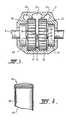
- a two-stroke internal combustion engine 1 comprising a crankcase 2, a cylinder component 3 and a cylinder head 4, which together define the cylinder 5.
- the end 6 of the cylinder at the crankcase is open while the cylinder head forms a closed end 7 of the cylinder to thus define a combustion chamber 8.
- a crankshaft 9 is rotatably mounted by means of bearings 10 in the crankcase.
- the crankshaft 9 includes a pair of flywheels 11 and 12 and a crankpin 13 connecting the flywheels.
- the crankshaft rotates in the direction indicated by the arrow 14.
- a piston 15 reciprocates in the cylinder and is connected to the crankshaft by a connecting rod 16.
- the combustible mixture for the engine is formed in a carburetor (not shown) and flows into the engine through an intake duct 17 which terminates in an intake port 18 in the cylinder wall.
- the exhaust gases of the engine flow from an exhaust port 19 in the cylinder wall out through an exhaust duct 20.
- the rotation of the crankshaft 9 inside the crankcase 2 in the direction of the arrow 14 causes a rotation of the combustible mixture inside the crankcase in the same direction.
- the rotation of the flywheels 11 and 12 acts to impart a flow to the combustible mixture immediately adjacent the periphery of the flywheels in the direction of the arrow 14.
- the transfer port 22 located immediately adjacent the crankcase 2 is located substantially radially with respect to the axis of rotation of the flywheels 11 and 12. This way, the transfer duct 22 is effectively placed in the path of the boundary layer rotating around the periphery of the flywheels 11 and 12 and its momentum used to transfer this combustible mixture through the transfer passage 21 into the combustion chamber 5.
- the efficiency of delivery of the combustible mixture as well as the transfer time is found to be greatly improved with respect to known two-stroke internal combustion engines.
- the relationshi of the transfer passage 21 may be better appreciated by referring to Figure 3, from which it can be seen that the transfer port 22 is located such that at least one plane of rotation of the flywheels 11 and 12 passes therethrough so as to directly transfer the combustible mixture rotating in the boundary layer around the periphery of the flywheels 11 and 12 directly into the transfer passage 21.
- one or more additional transfer ports 40 and 41 may be provided adjacent to the first transfer port 22 to increase the volume of combustible mixture transferred from the crankcase to the combustion chamber, thus improving the efficiency of the circulation of the combustible mixture in the two-stroke engine 1.
- the intake port 18 and associated intake duct 17 are oriented so as to deliver the combustible mixture provided to the engine directly into the crankcase.
- the intake duct 17 may be located such that its longitudinal axis 42 passes through one or more of the flywheels 11 and 12. Combustible mixture delivered through the intake duct in such an arrangement is delivered directly into the boundary layer circulating around the periphery of the flywheels 11 and 12. The delivery of this combustible mixture into the transfer passage 21 is therefore optimized.
- the intake duct 17, the transfer passage 21 and a plane of rotation of one or more of the flywheels 11 and 12 may be located in substantially the same plane.
- the combustible mixture introduced into the engine through the intake duct 17 and transferred across the cylinder 5 into the transfer passage 21 prior to use in the combustion chamber 5 and expulsion through the exhaust duct 20 remains substantially within the same plane and is thus not subjected to rapid changes in direction which would otherwise impair the efficiency of delivery of the combustible mixture.
- the rapidity of delivery of the combustible mixture as well as the general efficiency of the engine is therefore improved with respect to prior art two-stroke engines.
- the word “exterior” is meant to refer to those faces of the flywheel or flywheels which are not adjacent a face of another flywheel. Accordingly, the volume of the crankcase may be reduced, which results in a more efficient pumping of the combustible mixture being required by the engine and enables the rotational force of the flywheels 11 and 12 to be more efficiently transferred to that combustible mixture present within the crankcase 2.
- the transfer port 23 has a minimum radius 64 of 1.0 mm, and preferably 1.25 mm between the wall of the cylinder 5 and the transfer passage 21.
- the same minimum radius is applied to the transfer ports associated with the combustion chamber end of the additional transfer passages 40 and 41.
- the transfer port 22 has a minimum radius 65 of 2.0 mm, and preferably 2.5 mm, between the wall of the cylinder 5 and the transfer passage 21.
- the same minimum radius may also be applied to the corresponding transfer ports of the transfer passages 40 and 41.
- the minimum radius 65 between the wall of the cylinder 5 and the transfer passage progressively varies, for example, from a minimum of 2.0 mm at the wall of the cylinder 5 to a minimum of 13.0 mm adjacent the transfer passage 21 such that the transfer port 22 has a bell-shaped mouth.
- the transfer passages 21, 40 and 41 may each have a cross sectional area which progressively decreases along their respective lengths from their crankcase end to their combustion chamber end. Abrupt changes in cross sectional area and flow rates of the combustible mixture within these transfer passages are therefore avoided. It has been found in practice that a progressive decrease of approximately 20% along the length of the transfer passage is suitable for this purpose.
- vanes 47, 48 and 49 are provided on at least one of the faces of the flywheels 11 and 12. These vanes act to drive the combustible mixture present within the crankcase in the direction 14 of rotation of the flywheels 11 and 12.
- these vanes 47, 48 and 49 extend radially along a face of the flywheels 11 and 12.
- peripherally mounted vanes such as those referenced 50, 51 and 52 may be provided on a peripheral surface of one or more of the flywheels 11 and 12 in order to drive the boundary layer of combustible mixture around the periphery of the flywheels 11 and 12.
- Such vanes may be provided on one or more or all of the flywheels mounted within the crankcase 2.
- vanes 47, 48 and 49 shown in Figure 1, as well as the vanes 50, 51 and 52 shown in Figures 2 and 3 may be provided by projections from the flywheels 11 and 12 or by the provision of notches, grooves or other indentations in the flywheels 11 and 12.
- Figures 2 and 4 show respectively a front view and a side view of the piston 15.
- a front skirt 60 facing the transfer port 22 is contoured so as to minimize the restrictive and turbulent flow of the combustible mixture into the transfer passage 21 when the piston 15 is near the bottom of its travel in the cylinder 5.
- the skirt 60 includes a recess 61 having a shape substantially corresponding to that of the transfer port 22 and being coincident therewith when the piston 15 is near bottom-dead-centre.
- the skirt 60 may include additional recesses, such as those referenced 62 and 63, having shapes corresponding to that of transfer ports 40 and 41 and being coincident therewith when the piston 15 is near bottom-dead-centre.
Landscapes
- Engineering & Computer Science (AREA)
- Chemical & Material Sciences (AREA)
- Combustion & Propulsion (AREA)
- Mechanical Engineering (AREA)
- General Engineering & Computer Science (AREA)
- Cylinder Crankcases Of Internal Combustion Engines (AREA)
- Combustion Methods Of Internal-Combustion Engines (AREA)
- Fuel-Injection Apparatus (AREA)
Claims (12)
- Moteur à deux temps (1) commandé par des orifices, comprenant : une chambre de combustion (8), un carter (2) contenant un mélange combustible, un cylindre (5) ayant un avant et un arrière, un piston (6) travaillant dans le cylindre (5), un conduit d'admission (17) se terminant en un orifice d'admission (18) devant la paroi du cylindre pour délivrer le mélange combustible au moteur, un passage de transfert (21) s'étendant d'un premier orifice de transfert (22) à un deuxième orifice de transfert (23) à l'arrière de la paroi du cylindre adjacente à la chambre de combustion (8), pour faire passer le mélange combustible du carter (2) à la chambre de combustion (8), et au moins un volant (11, 12) est monté à rotation dans le carter (2) autour d'un axe de rotation, le volant (11, 12) ayant un plan de rotation qui passe par le premier orifice de transfert (22), le conduit d'admission (17) étant situé sensiblement dans le même plan que le plan de rotation du volant (11, 12), caractérisé en ce que le premier orifice de transfert (22) est placé à l'arrière de la paroi du cylindre adjacente audit carter (2), en ce que la rotation du volant agit pour entraíner la couche limite du mélange combustible immédiatement adjacente à la périphérie du volant (11, 12) autour de la périphérie dans le premier orifice de transfert (22), et en ce que l'orifice d'admission (18) et le conduit d'admission (17) sont orientés de manière à délivrer le mélange combustible directement dans le carter (2).
- Moteur à deux temps commandé par des orifices selon la revendication 1, caractérisé en ce que le plan de rotation passe par le premier orifice de transfert (22), le passage de transfert (21) et le deuxième orifice de transfert (23).
- Moteur à deux temps commandé par des orifices selon la revendication 1 ou 2, dans lequel le volant (11, 12) a deux faces opposées (43, 44) immédiatement adjacentes aux surfaces intérieures (45, 46) du carter.
- Moteur à deux temps commandé par des orifices selon l'une quelconque des revendications 1 à 3, dans lequel le deuxième orifice de transfert (23) dans la paroi du cylindre adjacente à la chambre de combustion (8) a un rayon minimum de 1,0 mm entre la paroi du cylindre et le passage de transfert (21).
- Moteur à deux temps commandé par des orifices selon l'une quelconque des revendications précédentes, dans lequel le premier orifice de transfert (22) a un rayon minimum de 2,0 mm.
- Moteur à deux temps commandé par des orifices selon la revendication 4, dans lequel le premier orifice de transfert (22) a un rayon minimum de 2,5 mm entre la paroi du cylindre (5) et le passage de transfert (21).
- Moteur à deux temps commandé par des orifices selon l'une quelconque des revendications précédentes, dans lequel le premier orifice de transfert (22) a un rayon minimum progressivement variable entre la paroi du cylindre (5) et le passage de transfert (21).
- Moteur à deux temps commandé par des orifices selon la revendication 7, dans lequel le rayon du premier orifice de transfert (22) progresse d'un minimum de 2,0 mm au niveau de la paroi du cylindre (5) à un minimum de 13 mm en une position adjacente au passage de transfert (21) de sorte que le premier orifice de transfert (22) a une embouchure en forme de cloche.
- Moteur à deux temps commandé par des orifices selon l'une quelconque des revendications précédentes, dans lequel le passage de transfert (21) a une section droite qui diminue progressivement le long de sa longueur, du premier orifice de transfert (22) au deuxième orifice de transfert (23).
- Moteur à deux temps commandé par des orifices selon l'une quelconque des revendications précédentes, dans lequel une ou plusieurs palette(s) (47, 48, 49) sont placées sur au moins l'une des faces (43, 44) du ou des volant(s) (11, 12) pour entraíner le mélange combustible dans le carter (2) dans le sens de rotation du ou des volant(s) (11, 12).
- Moteur à deux temps commandé par des orifices selon la revendication 9, dans lequel les palettes (47, 48, 49) s'étendent radialement le long d'au moins une face du ou des volant(s) (11, 12).
- Moteur à deux temps commandé par des orifices selon l'une quelconque des revendications précédentes, dans lequel une ou plusieurs palettes (51, 52, 53) sont placées sur une surface périphérique du ou des volant(s) (11, 12) pour entraíner la couche limite autour de la périphérie du ou des volant(s).
Applications Claiming Priority (3)
| Application Number | Priority Date | Filing Date | Title |
|---|---|---|---|
| AUPO6805A AUPO680597A0 (en) | 1997-05-15 | 1997-05-15 | Two-stroke intrernal combustion engine having improved fuel porting |
| AUPO680597 | 1997-05-15 | ||
| PCT/AU1998/000303 WO1998051909A1 (fr) | 1997-05-15 | 1998-04-27 | Moteur a combustion interne a deux temps avec amelioration du systeme de circulation de carburant |
Publications (3)
| Publication Number | Publication Date |
|---|---|
| EP1009925A1 EP1009925A1 (fr) | 2000-06-21 |
| EP1009925A4 EP1009925A4 (fr) | 2001-04-25 |
| EP1009925B1 true EP1009925B1 (fr) | 2003-07-09 |
Family
ID=3801096
Family Applications (1)
| Application Number | Title | Priority Date | Filing Date |
|---|---|---|---|
| EP98916659A Expired - Lifetime EP1009925B1 (fr) | 1997-05-15 | 1998-04-27 | Moteur a combustion interne a deux temps avec amelioration du systeme de circulation de carburant |
Country Status (9)
| Country | Link |
|---|---|
| US (1) | US6293234B1 (fr) |
| EP (1) | EP1009925B1 (fr) |
| JP (1) | JP2001524180A (fr) |
| AT (1) | ATE244817T1 (fr) |
| AU (1) | AUPO680597A0 (fr) |
| CA (1) | CA2289604A1 (fr) |
| DE (1) | DE69816309T2 (fr) |
| NZ (1) | NZ501095A (fr) |
| WO (1) | WO1998051909A1 (fr) |
Families Citing this family (6)
| Publication number | Priority date | Publication date | Assignee | Title |
|---|---|---|---|---|
| US7073474B2 (en) * | 2003-11-06 | 2006-07-11 | Brp Us Inc. | Flywheel with torsional dampening ring |
| US20100251994A1 (en) * | 2009-04-03 | 2010-10-07 | Nai Wen Liu | Remote control model engine assembly |
| US9068498B2 (en) | 2013-02-01 | 2015-06-30 | Achates Power, Inc. | Reduction of ring clipping in two-stroke cycle engines |
| JP6035197B2 (ja) * | 2013-04-30 | 2016-11-30 | 株式会社マキタ | 層状掃気2ストロークエンジン |
| JP6042767B2 (ja) * | 2013-04-30 | 2016-12-14 | 株式会社マキタ | 層状掃気2ストロークエンジン |
| EP4293210B1 (fr) * | 2022-06-13 | 2026-02-25 | Andreas Stihl AG & Co. KG | Moteur à deux temps |
Family Cites Families (13)
| Publication number | Priority date | Publication date | Assignee | Title |
|---|---|---|---|---|
| US4088097A (en) * | 1974-10-30 | 1978-05-09 | Harold Litz | Crankcase-scavenged engine |
| FR2425543B1 (fr) * | 1978-05-12 | 1986-02-07 | Univ Belfast | Moteur a combustion interne a deux temps |
| US4261306A (en) * | 1980-01-24 | 1981-04-14 | Gorr Eric D | Method and apparatus for improving performance of two-cycle gasoline engine |
| US4660514A (en) * | 1980-04-21 | 1987-04-28 | Outboard Marine Corporation | Two-cycle internal combustion engine including means for varying cylinder port timing |
| US4362132A (en) * | 1981-01-12 | 1982-12-07 | Neuman Clayton L | Two-cycle engine |
| DE3233108A1 (de) * | 1982-09-07 | 1984-03-08 | Norbert Dipl.-Ing. 3014 Laatzen Kania | Schnellaufende, schlitzgesteuerte zweitakt-brennkraftmaschine mit kurbelkammerspuelung |
| GB2142085B (en) * | 1983-04-28 | 1987-02-18 | Univ Belfast | Two-stroke crankcase compression engine |
| US4712520A (en) * | 1986-07-25 | 1987-12-15 | John Pasquin | Crank case compressor unit for a two cycle engine |
| US4899698A (en) * | 1987-10-30 | 1990-02-13 | Georges Thery | Combustion chamber for two-stroke reciprocating engine, and and engine making use thereof |
| FR2645207B1 (fr) * | 1989-04-04 | 1991-07-19 | Racing Kart Dev Ste Nl | Moteur a combustion interne a cycle deux temps |
| AU6276390A (en) * | 1989-08-10 | 1991-03-11 | Knitted Sleeve (Overseas) Ltd. | Improved two stoke cycle spark ignition internal combustion engine |
| JPH09158738A (ja) * | 1995-12-13 | 1997-06-17 | Daihatsu Motor Co Ltd | ユニフロー式掃気装置 |
| JPH09242546A (ja) * | 1996-03-08 | 1997-09-16 | Honda Motor Co Ltd | クランク室予圧縮型火花点火式2ストローク内燃機関 |
-
1997
- 1997-05-15 AU AUPO6805A patent/AUPO680597A0/en not_active Abandoned
-
1998
- 1998-04-27 JP JP54860798A patent/JP2001524180A/ja active Pending
- 1998-04-27 US US09/423,841 patent/US6293234B1/en not_active Expired - Fee Related
- 1998-04-27 DE DE69816309T patent/DE69816309T2/de not_active Expired - Fee Related
- 1998-04-27 CA CA002289604A patent/CA2289604A1/fr not_active Abandoned
- 1998-04-27 WO PCT/AU1998/000303 patent/WO1998051909A1/fr not_active Ceased
- 1998-04-27 AT AT98916659T patent/ATE244817T1/de not_active IP Right Cessation
- 1998-04-27 NZ NZ501095A patent/NZ501095A/xx unknown
- 1998-04-27 EP EP98916659A patent/EP1009925B1/fr not_active Expired - Lifetime
Also Published As
| Publication number | Publication date |
|---|---|
| JP2001524180A (ja) | 2001-11-27 |
| NZ501095A (en) | 2000-05-26 |
| ATE244817T1 (de) | 2003-07-15 |
| WO1998051909A1 (fr) | 1998-11-19 |
| CA2289604A1 (fr) | 1998-11-19 |
| AUPO680597A0 (en) | 1997-06-05 |
| EP1009925A1 (fr) | 2000-06-21 |
| EP1009925A4 (fr) | 2001-04-25 |
| DE69816309T2 (de) | 2004-05-13 |
| DE69816309D1 (de) | 2003-08-14 |
| US6293234B1 (en) | 2001-09-25 |
Similar Documents
| Publication | Publication Date | Title |
|---|---|---|
| US8141536B2 (en) | Air cleaner for stratified-scavenging two-stroke internal combustion engine | |
| US6640755B2 (en) | Two-cycle internal combustion engine | |
| US4598673A (en) | Air-scavenged two-cycle internal combustion engine | |
| US6450135B1 (en) | Two-stroke internal combustion engine | |
| EP1009925B1 (fr) | Moteur a combustion interne a deux temps avec amelioration du systeme de circulation de carburant | |
| JP3703924B2 (ja) | 2サイクル内燃エンジン | |
| US7243622B2 (en) | Two-stroke internal combustion engine | |
| JP2000179346A (ja) | 2サイクルエンジン | |
| US7322322B2 (en) | Stratified-scavenging two-stroke internal combustion engine | |
| JP4249638B2 (ja) | 2サイクルエンジン | |
| US6173683B1 (en) | Two-stroke cycle engine | |
| EP1069294B1 (fr) | Moteur à combustion interne à deux temps | |
| AU735629B2 (en) | Two-stroke internal combustion engine having improved fuel porting | |
| US2529864A (en) | Supercharger | |
| JP2008274804A (ja) | 2サイクルエンジン | |
| US4305361A (en) | Two cycle baffled piston engine with post-baffle scavenging | |
| US3074388A (en) | Two-cycle cross-flow internal combustion engine with fuel injection | |
| JP2001329844A (ja) | 2サイクルエンジン | |
| JP7641846B2 (ja) | 2サイクルエンジン | |
| JP4272001B2 (ja) | 2サイクルエンジン | |
| JPH01106910A (ja) | ロータリバルブ式内燃機関 | |
| JPS5815713A (ja) | ポ−ト掃気式2サイクルエンジン | |
| JP2001355451A (ja) | 層状掃気2行程内燃機関 | |
| JP2000310123A (ja) | 2サイクル内燃エンジン | |
| IT202400000063A1 (it) | Motore a combustione interna a due tempi con sistema di travaso perfezionato |
Legal Events
| Date | Code | Title | Description |
|---|---|---|---|
| PUAI | Public reference made under article 153(3) epc to a published international application that has entered the european phase |
Free format text: ORIGINAL CODE: 0009012 |
|
| 17P | Request for examination filed |
Effective date: 19991118 |
|
| AK | Designated contracting states |
Kind code of ref document: A1 Designated state(s): AT BE CH CY DE DK ES FI FR GB GR IE IT LI LU MC NL PT SE |
|
| A4 | Supplementary search report drawn up and despatched |
Effective date: 20010309 |
|
| AK | Designated contracting states |
Kind code of ref document: A4 Designated state(s): AT BE CH CY DE DK ES FI FR GB GR IE IT LI LU MC NL PT SE |
|
| 17Q | First examination report despatched |
Effective date: 20011127 |
|
| GRAH | Despatch of communication of intention to grant a patent |
Free format text: ORIGINAL CODE: EPIDOS IGRA |
|
| GRAH | Despatch of communication of intention to grant a patent |
Free format text: ORIGINAL CODE: EPIDOS IGRA |
|
| GRAA | (expected) grant |
Free format text: ORIGINAL CODE: 0009210 |
|
| AK | Designated contracting states |
Designated state(s): AT BE CH CY DE DK ES FI FR GB GR IE IT LI LU MC NL PT SE |
|
| PG25 | Lapsed in a contracting state [announced via postgrant information from national office to epo] |
Ref country code: NL Free format text: LAPSE BECAUSE OF FAILURE TO SUBMIT A TRANSLATION OF THE DESCRIPTION OR TO PAY THE FEE WITHIN THE PRESCRIBED TIME-LIMIT Effective date: 20030709 Ref country code: LI Free format text: LAPSE BECAUSE OF FAILURE TO SUBMIT A TRANSLATION OF THE DESCRIPTION OR TO PAY THE FEE WITHIN THE PRESCRIBED TIME-LIMIT Effective date: 20030709 Ref country code: FI Free format text: LAPSE BECAUSE OF FAILURE TO SUBMIT A TRANSLATION OF THE DESCRIPTION OR TO PAY THE FEE WITHIN THE PRESCRIBED TIME-LIMIT Effective date: 20030709 Ref country code: CY Free format text: LAPSE BECAUSE OF FAILURE TO SUBMIT A TRANSLATION OF THE DESCRIPTION OR TO PAY THE FEE WITHIN THE PRESCRIBED TIME-LIMIT Effective date: 20030709 Ref country code: CH Free format text: LAPSE BECAUSE OF FAILURE TO SUBMIT A TRANSLATION OF THE DESCRIPTION OR TO PAY THE FEE WITHIN THE PRESCRIBED TIME-LIMIT Effective date: 20030709 Ref country code: BE Free format text: LAPSE BECAUSE OF FAILURE TO SUBMIT A TRANSLATION OF THE DESCRIPTION OR TO PAY THE FEE WITHIN THE PRESCRIBED TIME-LIMIT Effective date: 20030709 Ref country code: AT Free format text: LAPSE BECAUSE OF FAILURE TO SUBMIT A TRANSLATION OF THE DESCRIPTION OR TO PAY THE FEE WITHIN THE PRESCRIBED TIME-LIMIT Effective date: 20030709 |
|
| REG | Reference to a national code |
Ref country code: GB Ref legal event code: FG4D |
|
| REG | Reference to a national code |
Ref country code: CH Ref legal event code: EP |
|
| REF | Corresponds to: |
Ref document number: 69816309 Country of ref document: DE Date of ref document: 20030814 Kind code of ref document: P |
|
| REG | Reference to a national code |
Ref country code: IE Ref legal event code: FG4D |
|
| PG25 | Lapsed in a contracting state [announced via postgrant information from national office to epo] |
Ref country code: SE Free format text: LAPSE BECAUSE OF FAILURE TO SUBMIT A TRANSLATION OF THE DESCRIPTION OR TO PAY THE FEE WITHIN THE PRESCRIBED TIME-LIMIT Effective date: 20031009 Ref country code: GR Free format text: LAPSE BECAUSE OF FAILURE TO SUBMIT A TRANSLATION OF THE DESCRIPTION OR TO PAY THE FEE WITHIN THE PRESCRIBED TIME-LIMIT Effective date: 20031009 Ref country code: DK Free format text: LAPSE BECAUSE OF FAILURE TO SUBMIT A TRANSLATION OF THE DESCRIPTION OR TO PAY THE FEE WITHIN THE PRESCRIBED TIME-LIMIT Effective date: 20031009 |
|
| PG25 | Lapsed in a contracting state [announced via postgrant information from national office to epo] |
Ref country code: ES Free format text: LAPSE BECAUSE OF FAILURE TO SUBMIT A TRANSLATION OF THE DESCRIPTION OR TO PAY THE FEE WITHIN THE PRESCRIBED TIME-LIMIT Effective date: 20031020 |
|
| NLV1 | Nl: lapsed or annulled due to failure to fulfill the requirements of art. 29p and 29m of the patents act | ||
| PG25 | Lapsed in a contracting state [announced via postgrant information from national office to epo] |
Ref country code: PT Free format text: LAPSE BECAUSE OF FAILURE TO SUBMIT A TRANSLATION OF THE DESCRIPTION OR TO PAY THE FEE WITHIN THE PRESCRIBED TIME-LIMIT Effective date: 20031209 |
|
| REG | Reference to a national code |
Ref country code: CH Ref legal event code: PL |
|
| ET | Fr: translation filed | ||
| PG25 | Lapsed in a contracting state [announced via postgrant information from national office to epo] |
Ref country code: LU Free format text: LAPSE BECAUSE OF NON-PAYMENT OF DUE FEES Effective date: 20040427 Ref country code: IE Free format text: LAPSE BECAUSE OF NON-PAYMENT OF DUE FEES Effective date: 20040427 |
|
| PG25 | Lapsed in a contracting state [announced via postgrant information from national office to epo] |
Ref country code: MC Free format text: LAPSE BECAUSE OF NON-PAYMENT OF DUE FEES Effective date: 20040430 |
|
| PLBE | No opposition filed within time limit |
Free format text: ORIGINAL CODE: 0009261 |
|
| STAA | Information on the status of an ep patent application or granted ep patent |
Free format text: STATUS: NO OPPOSITION FILED WITHIN TIME LIMIT |
|
| 26N | No opposition filed |
Effective date: 20040414 |
|
| PG25 | Lapsed in a contracting state [announced via postgrant information from national office to epo] |
Ref country code: FR Free format text: LAPSE BECAUSE OF NON-PAYMENT OF DUE FEES Effective date: 20041231 |
|
| REG | Reference to a national code |
Ref country code: FR Ref legal event code: ST |
|
| REG | Reference to a national code |
Ref country code: IE Ref legal event code: MM4A |
|
| PGFP | Annual fee paid to national office [announced via postgrant information from national office to epo] |
Ref country code: IT Payment date: 20060430 Year of fee payment: 9 |
|
| PGFP | Annual fee paid to national office [announced via postgrant information from national office to epo] |
Ref country code: GB Payment date: 20060530 Year of fee payment: 9 |
|
| PGFP | Annual fee paid to national office [announced via postgrant information from national office to epo] |
Ref country code: DE Payment date: 20060616 Year of fee payment: 9 |
|
| GBPC | Gb: european patent ceased through non-payment of renewal fee |
Effective date: 20070427 |
|
| PG25 | Lapsed in a contracting state [announced via postgrant information from national office to epo] |
Ref country code: DE Free format text: LAPSE BECAUSE OF NON-PAYMENT OF DUE FEES Effective date: 20071101 |
|
| PG25 | Lapsed in a contracting state [announced via postgrant information from national office to epo] |
Ref country code: GB Free format text: LAPSE BECAUSE OF NON-PAYMENT OF DUE FEES Effective date: 20070427 |
|
| PG25 | Lapsed in a contracting state [announced via postgrant information from national office to epo] |
Ref country code: IT Free format text: LAPSE BECAUSE OF NON-PAYMENT OF DUE FEES Effective date: 20070427 |