EP1010548A2 - Bandage pneumatique radial - Google Patents
Bandage pneumatique radial Download PDFInfo
- Publication number
- EP1010548A2 EP1010548A2 EP99309969A EP99309969A EP1010548A2 EP 1010548 A2 EP1010548 A2 EP 1010548A2 EP 99309969 A EP99309969 A EP 99309969A EP 99309969 A EP99309969 A EP 99309969A EP 1010548 A2 EP1010548 A2 EP 1010548A2
- Authority
- EP
- European Patent Office
- Prior art keywords
- steel
- carcass
- steel cord
- filament
- pneumatic radial
- Prior art date
- Legal status (The legal status is an assumption and is not a legal conclusion. Google has not performed a legal analysis and makes no representation as to the accuracy of the status listed.)
- Granted
Links
Images



Classifications
-
- D—TEXTILES; PAPER
- D07—ROPES; CABLES OTHER THAN ELECTRIC
- D07B—ROPES OR CABLES IN GENERAL
- D07B1/00—Constructional features of ropes or cables
- D07B1/06—Ropes or cables built-up from metal wires, e.g. of section wires around a hemp core
- D07B1/0606—Reinforcing cords for rubber or plastic articles
- D07B1/0646—Reinforcing cords for rubber or plastic articles comprising longitudinally preformed wires
- D07B1/0653—Reinforcing cords for rubber or plastic articles comprising longitudinally preformed wires in the core
-
- B—PERFORMING OPERATIONS; TRANSPORTING
- B60—VEHICLES IN GENERAL
- B60C—VEHICLE TYRES; TYRE INFLATION; TYRE CHANGING; CONNECTING VALVES TO INFLATABLE ELASTIC BODIES IN GENERAL; DEVICES OR ARRANGEMENTS RELATED TO TYRES
- B60C9/00—Reinforcements or ply arrangement of pneumatic tyres
- B60C9/0007—Reinforcements made of metallic elements, e.g. cords, yarns, filaments or fibres made from metal
-
- B—PERFORMING OPERATIONS; TRANSPORTING
- B60—VEHICLES IN GENERAL
- B60C—VEHICLE TYRES; TYRE INFLATION; TYRE CHANGING; CONNECTING VALVES TO INFLATABLE ELASTIC BODIES IN GENERAL; DEVICES OR ARRANGEMENTS RELATED TO TYRES
- B60C9/00—Reinforcements or ply arrangement of pneumatic tyres
- B60C9/0064—Reinforcements comprising monofilaments
-
- B—PERFORMING OPERATIONS; TRANSPORTING
- B60—VEHICLES IN GENERAL
- B60C—VEHICLE TYRES; TYRE INFLATION; TYRE CHANGING; CONNECTING VALVES TO INFLATABLE ELASTIC BODIES IN GENERAL; DEVICES OR ARRANGEMENTS RELATED TO TYRES
- B60C9/00—Reinforcements or ply arrangement of pneumatic tyres
- B60C9/02—Carcasses
- B60C9/04—Carcasses the reinforcing cords of each carcass ply arranged in a substantially parallel relationship
- B60C9/08—Carcasses the reinforcing cords of each carcass ply arranged in a substantially parallel relationship the cords extend transversely from bead to bead, i.e. radial ply
-
- D—TEXTILES; PAPER
- D07—ROPES; CABLES OTHER THAN ELECTRIC
- D07B—ROPES OR CABLES IN GENERAL
- D07B2201/00—Ropes or cables
- D07B2201/20—Rope or cable components
- D07B2201/2015—Strands
- D07B2201/2023—Strands with core
-
- D—TEXTILES; PAPER
- D07—ROPES; CABLES OTHER THAN ELECTRIC
- D07B—ROPES OR CABLES IN GENERAL
- D07B2501/00—Application field
- D07B2501/20—Application field related to ropes or cables
- D07B2501/2046—Tyre cords
-
- Y—GENERAL TAGGING OF NEW TECHNOLOGICAL DEVELOPMENTS; GENERAL TAGGING OF CROSS-SECTIONAL TECHNOLOGIES SPANNING OVER SEVERAL SECTIONS OF THE IPC; TECHNICAL SUBJECTS COVERED BY FORMER USPC CROSS-REFERENCE ART COLLECTIONS [XRACs] AND DIGESTS
- Y10—TECHNICAL SUBJECTS COVERED BY FORMER USPC
- Y10S—TECHNICAL SUBJECTS COVERED BY FORMER USPC CROSS-REFERENCE ART COLLECTIONS [XRACs] AND DIGESTS
- Y10S57/00—Textiles: spinning, twisting, and twining
- Y10S57/902—Reinforcing or tyre cords
-
- Y—GENERAL TAGGING OF NEW TECHNOLOGICAL DEVELOPMENTS; GENERAL TAGGING OF CROSS-SECTIONAL TECHNOLOGIES SPANNING OVER SEVERAL SECTIONS OF THE IPC; TECHNICAL SUBJECTS COVERED BY FORMER USPC CROSS-REFERENCE ART COLLECTIONS [XRACs] AND DIGESTS
- Y10—TECHNICAL SUBJECTS COVERED BY FORMER USPC
- Y10T—TECHNICAL SUBJECTS COVERED BY FORMER US CLASSIFICATION
- Y10T152/00—Resilient tires and wheels
- Y10T152/10—Tires, resilient
- Y10T152/10495—Pneumatic tire or inner tube
- Y10T152/10765—Characterized by belt or breaker structure
Definitions
- the present invention relates to a pneumatic radial tire, particularly to a pneumatic radial tire for passenger cars, having a decreased weight and exhibiting excellent durability, riding comfort and controllability.
- organic fibers have been used for the carcass of pneumatic radial tires for passenger cars.
- polyesters are mainly used and rayon and nylon are occasionally used.
- the present invention has been made under the above circumstances and an object of the present invention is to provide a pneumatic radial tire for passenger cars which can suppress deterioration in durability of a carcass which takes place due to buckling deformation when a steel cord is applied to the carcass of the pneumatic radial tire, which has a decreased weight due to application of a high strength steel cord and which exhibits improved riding comfort and controllability.
- tensile rigidity of the carcass is kept smaller than that of conventional carcasses by application of the steel cord having a smaller Young's modulus to the carcass.
- buckling deformation of the steel cord is prevented and durability is improved.
- tensile strength, TS of the steel filament in the steel cord satisfies an equation (2) as follows: TS(kgf/mm 2 ) ⁇ 230 - 148 log d wherein
- a high strength steel cord formed with steel filaments having a great tensile strength is used for the carcass.
- input force (tensile stress) per unit sectional area of the steel filament forming the steel cord increases when tensile force works on the carcass and the extension (elongation) increases.
- tensile rigidity of the carcass decreases.
- durability is improved due to the decrease in tensile rigidity of the carcass.
- the amount of the cord necessary for maintaining the required strength of the carcass is decreased by the application of the high strength steel cord and the weight of the tire can be decreased.
- the diameter of the steel filament in the steel cord is 0.10 to 0.32 mm.
- Figure 1 shows a cross section of a pneumatic radial tire of an embodiment of the present invention.
- Figure 2 shows a diagram exhibiting the relation between elongation and the applied load in the tensile test of a steel cord.
- Figure 3 shows a diagram exhibiting the pitch between adjacent steel cords in a carcass, in a cross section along the equatorial line of a tire.
- Figure 4 shows a side view of a steel filament formed into a helical shape.
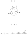
- Figure 5 shows a cross section of the steel cord used in Example 3.
- Figure 6 shows a side view of a steel cord filament formed into a waved shape.
- Figure 7 shows a cross section of the steel cord used in Example 8.
- the pneumatic radial tire 10 comprises a carcass 14 which is a ply of cords disposed in the radial direction of the tire and which extends in a toroidal form between a pair of beads 12 and belts 16 disposed at a crown portion 15 at an outer side of the carcass 14 in the radial direction of the tire.
- steel cords 20 comprising at least one steel filament 18 (five filaments in Figure 3) are disposed parallel to each other with a prescribed pitch between them.
- the (strike) pitch S between adjacent steel cords at the crown portion is the pitch (distance) between the centers of adjacent steel cords 20 in the carcass 14 in the cross section along the equatorial line of the tire (refer to Figure 3).
- D and d indicate diameters of the steel cord 20 and the steel filament 18, respectively.
- the pneumatic radial tire 10 of the present embodiment is characterized in that tensile rigidity of the carcass 14 comprising the steel cord 20 is kept within an appropriate range to improve durability of the carcass.
- Tensile force in the circumferential direction of the tire works on a belt in a pneumatic radial tire when the tire is inflated by an inner pressure.
- a particularly great tensile stress works on the portion at the inner side of the equatorial plane of the tire (with respect to the turn in the tire) attached at the outer side of the vehicle with respect to the turn.
- the belt extends greatly in the circumferential direction of the tire and contracts in the transverse direction of the tire.
- a great compression stress works on steel cords of the carcass disposed in the direction perpendicular to the direction of the belt.
- a steel cord having a smaller Young's modulus is applied in the carcass. The reason is that a decrease in the Young's modulus of the steel cord used for reinforcing the carcass should decrease tensile rigidity of the carcass.
- tensile rigidity EL of the carcass is in the range of 1,300 to 2,400 kgf/mm 2 .
- tensile rigidity EL of the carcass is less than 1,300 kgf/mm 2 , the amount of the steel cord used in the carcass must be decreased to a great extent and it becomes difficult for the strength required for the carcass to be maintained.
- the strength required for the carcass can be maintained by increasing tensile strength of the steel filament constituting the steel.
- increasing the tensile strength of the steel filament causes a great decrease in the manufacturing productivity in the step of stretching the filament and is therefore economically disadvantageous.
- the tensile rigidity EL of the carcass exceeds 2,400 kgf/mm 2
- the tensile rigidity of the carcass becomes as high as that of carcasses having conventional steel cords and compression stress works repeatedly on the steel cord during rotation of the tire.
- the buckling deformation of the steel cord takes place at the time when the vehicle turns, deteriorating durability.
- tensile rigidity EL of the carcass 14 be in the range of 1,300 to 2,400 kgf/mm 2 . Durability of the carcass 14 is improved under this condition.
- tensile strength TS of the steel filament 18 forming the steel cord 20 satisfies the following equation (2): TS(kgf/mm 2 ) ⁇ 230 - 148 log d wherein
- the amount of the cord necessary for maintaining the required strength of the carcass is decreased by the application of the high strength steel cord and the weight of the tire can be decreased.
- the diameter of the steel filament 18 forming the steel cord 20 is 0.10 to 0.32 mm.
- the tensile rigidity of the carcass 14 can be made smaller than that of a carcass using a conventional steel cord and durability can be improved.
- a steel cord comprising a single steel filament which is held in the original straight form may be applied in the carcass.
- the steel filament is formed into a helical shape (refer to Figure 4) or a waved shape (refer to Figure 6).
- the structure of a steel cord formed with two or more steel filaments is not particularly limited. It is preferable that the steel cord has an open twist structure in which adjacent steel filaments are disposed with a pitch between them, or that at least one steel filament is formed into a helical shape or a waved shape having a pitch smaller than a pitch of twisting in the steel cord, because penetratability of rubber increases and tensile rigidity of the carcass decreases.
- durability of a carcass of a pneumatic tire depends significantly on the tensile rigidity of the carcass.
- the residual stress at a surface layer of the steel filament forming the steel cord is compression stress.
- Example 1 2 3 4 5 6 7 Number of carcasses 1 1 1 1 1 1 1 1 1 1 Cord structure 1 ⁇ 1 ⁇ 1 ⁇ 2 ⁇ 1 ⁇ 3 ⁇ 1 ⁇ 4 ⁇ 1 ⁇ 5 ⁇ 1+4 ⁇ 1+5 ⁇ 0.31 0.30 0.20 0.175 0.15 0.19 0.18
- Strength of cord (kg) 32 55 37 39 36 55 63 Diameter of steel cord (mm) 0.47 0.60 0.52 0.51 0.49 0.57 0.54 Number of cords per unit width 37.5 22.0 32.3 31.0 33.4 22.0 18.9 of ply (/50 mm) Pitch between adjacent 1.33 2.28 1.55 1.61 1.50 2.28 2.64 steel cords in crown portion (mm)
- Durability of carcass cord good good good good good good good good good good good good good good Riding comfort (index) 100 100 105
- a steel cord embedded in a carcass (in the condition in which the steel cord was covered with rubber) was subjected to a tensile test and the relation between the elongation and the applied load such as that shown in Figure 2 was obtained. Young's modulus of the steel cord was obtained from the slope of the curve and the tensile rigidity was obtained in accordance with equation (1) described in Claim 1.
- Tires inflated by an inner pressure of 2.0 kgf/cm 2 were attached to an ordinary passenger car.
- the passenger car was driven on a test course and side force was applied, and thereafter, fracturing of steel cords in the carcass was examined.
- the result was evaluated as good.
- the result was evaluated as fair.
- the result was evaluated as poor.
- Tires inflated by an inner pressure of 2.0 kgf/cm 2 were attached to an ordinary passenger car.
- the riding comfort was evaluated and expressed as a number based on the impression of the driver while driving the passenger car on a test course.
- the result is expressed as an index based on the value obtained in Comparative Example 1, which was set at 100. The greater the value, the better the riding comfort.
- Tires inflated by an inner pressure of 2.0 kgf/cm 2 were attached to an ordinary passenger car.
- the controllability was evaluated and expressed as a number based on the impression of the driver while driving the passenger car on a test course.
- the result is expressed as an index based on the value obtained in Comparative Example 1, which was set at 100. The greater the value, the better the controllability.
- the weight of the steel cords embedded in the carcass is expressed as an index based on the value obtained in Comparative Example 1, which was set at 100. The smaller the value, the more reduced the weight.
- the tires of the present invention in Examples 1 to 13 all showed more excellent durability than that of the tire in Comparative Example 1 and exhibited riding comfort and controllability which were the same as or more excellent than those of the tire in Comparative Example 1.
- the tires of the present invention showed advantageous results with respect to reducing the weight of the tire as well.
- the cord used in Example 1 had the structure shown in Figure 4 which comprised a single steel filament formed into a helical shape.
- the cords used in Examples 3 to 5 had the structures in which adjacent filaments are disposed with a pitch between them.
- the cross-section of the cord used in Example 3 is shown in Figure 5.
- the cord used in Example 8 had the structure in which the core filament was formed into a waved shape as shown in Figure 6 and a sheath of 6 filaments was twisted around the core filament.
- the cross-section of this cord is shown in Figure 7.
- Tires of Comparative Examples 1 to 6 shown in Table 3 all had carcasses having very great tensile rigidity and showed inferior durability of carcass cords.
- the tire of Comparative Example 3 had a carcass having particularly great tensile rigidity and the controllability was inferior to that of the tire of Comparative Example 1.
- the tensile strength of the steel filament in this tire was very small and the weight of the carcass was greater than that of the tire of Comparative Example 1.
- the tire of Comparative Example 4 had a carcass having particularly great tensile rigidity and showed inferior controllability to that of the tire of Comparative Example 1.
- the tire of Comparative Example 6 had a steel filament having a small tensile strength and the weight of a carcass thereof was greater than that of the tire of Comparative Example 1.
- the pneumatic radial tire of the present invention which satisfies the aforementioned conditions exhibits an excellent balance of durability of the carcass cord, riding comfort and controllability and, moreover, the weight of the tire can be decreased.
- tensile rigidity of the carcass was decreased and durability was improved by the use of the high strength steel cord in decreased amounts in a carcass. Similar effects can be obtained by the use of a cord having a smaller tensile rigidity such as a highly stretched steel cord twisted at a greater angle.
- a pneumatic radial tire exhibiting more excellent durability and controllability than those of tires using organic fibers in the carcass can be provided.
- a pneumatic radial having a decreased weight and exhibiting excellent riding comfort can be provided by adjusting tensile rigidity of the carcass, tensile strength of the steel filament or the diameter of the steel filament in respective prescribed ranges.
Landscapes
- Engineering & Computer Science (AREA)
- Mechanical Engineering (AREA)
- Tires In General (AREA)
- Ropes Or Cables (AREA)
Applications Claiming Priority (2)
| Application Number | Priority Date | Filing Date | Title |
|---|---|---|---|
| JP35505898 | 1998-12-14 | ||
| JP10355058A JP2000177312A (ja) | 1998-12-14 | 1998-12-14 | 空気入りラジアルタイヤ |
Publications (3)
| Publication Number | Publication Date |
|---|---|
| EP1010548A2 true EP1010548A2 (fr) | 2000-06-21 |
| EP1010548A3 EP1010548A3 (fr) | 2002-01-30 |
| EP1010548B1 EP1010548B1 (fr) | 2006-02-15 |
Family
ID=18441698
Family Applications (1)
| Application Number | Title | Priority Date | Filing Date |
|---|---|---|---|
| EP99309969A Expired - Lifetime EP1010548B1 (fr) | 1998-12-14 | 1999-12-10 | Bandage pneumatique radial |
Country Status (5)
| Country | Link |
|---|---|
| US (1) | US6530410B1 (fr) |
| EP (1) | EP1010548B1 (fr) |
| JP (1) | JP2000177312A (fr) |
| DE (1) | DE69929864T2 (fr) |
| ES (1) | ES2257012T3 (fr) |
Cited By (6)
| Publication number | Priority date | Publication date | Assignee | Title |
|---|---|---|---|---|
| US6530410B1 (en) * | 1998-12-14 | 2003-03-11 | Bridgestone Corporation | Pneumatic radial tire |
| EP1314812A3 (fr) * | 2001-11-22 | 2004-07-07 | Sumitomo Rubber Industries Ltd. | Câble métallique et pneumatique comportant un tel câble métallique |
| CN102642448A (zh) * | 2012-04-27 | 2012-08-22 | 张国清 | 一种防爆胎的安全充气轮胎 |
| WO2015162178A1 (fr) * | 2014-04-25 | 2015-10-29 | Compagnie Generale Des Etablissements Michelin | Pneumatique comprenant une nappe de carcasse comprenant des éléments de renfort de carcasse gainés |
| EP3025873A4 (fr) * | 2013-07-22 | 2016-08-10 | Bridgestone Corp | Pneumatique |
| CN108202563A (zh) * | 2016-12-20 | 2018-06-26 | 固特异轮胎和橡胶公司 | 具有用钢丝帘线加强的单个胎体帘布层的充气轮胎 |
Families Citing this family (18)
| Publication number | Priority date | Publication date | Assignee | Title |
|---|---|---|---|---|
| JP2002326505A (ja) * | 2001-05-01 | 2002-11-12 | Yokohama Rubber Co Ltd:The | 乗用車用空気入りラジアルタイヤ |
| DE10152165A1 (de) * | 2001-10-23 | 2003-05-15 | Continental Ag | Fahrzeugluftreifen |
| JP4138296B2 (ja) * | 2001-11-01 | 2008-08-27 | 住友ゴム工業株式会社 | 空気入りタイヤ |
| US6949149B2 (en) * | 2002-12-18 | 2005-09-27 | The Goodyear Tire & Rubber Company | High strength, high carbon steel wire |
| KR100579532B1 (ko) * | 2003-11-25 | 2006-05-12 | 한국타이어 주식회사 | 경량화 및 내구성능이 향상된 타이어 |
| JP4940753B2 (ja) * | 2006-05-15 | 2012-05-30 | 横浜ゴム株式会社 | ゴム補強用スチールコード及びそれを用いた空気入りラジアルタイヤの製造方法 |
| US20100038006A1 (en) * | 2007-03-20 | 2010-02-18 | Bridgestone Corporation | Tire for two-wheeled vehicle |
| FR3008349B1 (fr) * | 2013-07-12 | 2015-08-07 | Michelin & Cie | Pneumatique comportant une armature de carcasse assouplie |
| FR3008350B1 (fr) * | 2013-07-12 | 2015-08-07 | Michelin & Cie | Pneumatique comportant des cables d'armatures de carcasse presentant une faible permeabilite |
| FR3008351B1 (fr) * | 2013-07-12 | 2015-08-07 | Michelin & Cie | Pneumatique comportant des epaisseurs variables des melanges caoutchouteux interieurs a l'armature de carcasse |
| FR3040911A1 (fr) * | 2015-09-16 | 2017-03-17 | Michelin & Cie | Pneumatique comportant des cables d'armatures de carcasse presentant un bas taux de carbone |
| US20190039415A1 (en) * | 2016-01-29 | 2019-02-07 | Firestone Industrial Products Company, Llc | Elastomeric articles as well as devices including same and methods of manufacture |
| EP3441239B1 (fr) * | 2016-04-08 | 2024-05-15 | The Yokohama Rubber Co., Ltd. | Bandage pneumatique |
| US20180117969A1 (en) * | 2016-11-02 | 2018-05-03 | Qingdao Doublestar Tire Industrial Co., Ltd. | Passenger all-steel tire and turn up process in building process thereof |
| JP6965597B2 (ja) * | 2017-06-26 | 2021-11-10 | 住友ゴム工業株式会社 | ランフラットタイヤ及びその製造方法 |
| WO2020080441A1 (fr) * | 2018-10-17 | 2020-04-23 | 株式会社ブリヂストン | Corps composite élastomère-câblé métallique et pneu l'employant |
| CN110329008A (zh) * | 2019-06-26 | 2019-10-15 | 青岛双星轮胎工业有限公司 | 一种全钢子午线轿车轮胎胎体的帘布 |
| JP7690384B2 (ja) * | 2021-11-25 | 2025-06-10 | 株式会社ブリヂストン | 空気入りタイヤ |
Family Cites Families (13)
| Publication number | Priority date | Publication date | Assignee | Title |
|---|---|---|---|---|
| US4836262A (en) * | 1986-08-08 | 1989-06-06 | Bridgestone Corporation | Metal cords and pneumatic tires using the same |
| US5223060A (en) * | 1988-10-26 | 1993-06-29 | The Yokohama Rubber Co., Ltd. | Pneumatic radial tire including steel cords of flat oblong cross-sectional configuration |
| JP2936112B2 (ja) * | 1988-11-11 | 1999-08-23 | 株式会社ブリヂストン | 補強用スチールコード |
| US5285623A (en) * | 1989-04-03 | 1994-02-15 | N.V. Bekaert S.A. | Steel cord with improved fatigue strength |
| DE69318582T2 (de) * | 1992-01-09 | 1998-09-17 | Bridgestone Corp | Stahlseil |
| KR940006811A (ko) * | 1992-09-18 | 1994-04-25 | 카알 에이취. 크루코우 | 카아커스플라이에 강으로된 모노필라멘트를 갖는 래디얼 타이어 |
| US5603208A (en) * | 1992-12-10 | 1997-02-18 | Bridgestone Bekaert Steel Cord Co., Ltd. | Composite rubber bodies using steel cords for the reinforcement of rubber articles |
| JP3222257B2 (ja) * | 1993-04-09 | 2001-10-22 | 株式会社ブリヂストン | ゴム物品補強用スチールコード及びそれを用いた空気入りラジアルタイヤ |
| JPH07242102A (ja) * | 1993-11-29 | 1995-09-19 | Bridgestone Corp | 重荷重用空気入りタイヤ |
| AU683522B2 (en) * | 1993-12-15 | 1997-11-13 | N.V. Bekaert S.A. | Open steel cord structure |
| US5779829A (en) * | 1995-08-24 | 1998-07-14 | The Goodyear Tire & Rubber Company | Pneumatic tire having a single carcass ply reinforced with metallic cords, a high ending ply, turnup and locked bead construction |
| JP3643123B2 (ja) * | 1996-04-18 | 2005-04-27 | 株式会社ブリヂストン | ゴム物品補強用スチールコード及び空気入りタイヤ |
| JP2000177312A (ja) * | 1998-12-14 | 2000-06-27 | Bridgestone Corp | 空気入りラジアルタイヤ |
-
1998
- 1998-12-14 JP JP10355058A patent/JP2000177312A/ja active Pending
-
1999
- 1999-12-10 EP EP99309969A patent/EP1010548B1/fr not_active Expired - Lifetime
- 1999-12-10 ES ES99309969T patent/ES2257012T3/es not_active Expired - Lifetime
- 1999-12-10 DE DE69929864T patent/DE69929864T2/de not_active Expired - Fee Related
- 1999-12-14 US US09/460,729 patent/US6530410B1/en not_active Expired - Fee Related
Cited By (9)
| Publication number | Priority date | Publication date | Assignee | Title |
|---|---|---|---|---|
| US6530410B1 (en) * | 1998-12-14 | 2003-03-11 | Bridgestone Corporation | Pneumatic radial tire |
| EP1314812A3 (fr) * | 2001-11-22 | 2004-07-07 | Sumitomo Rubber Industries Ltd. | Câble métallique et pneumatique comportant un tel câble métallique |
| US7131257B2 (en) | 2001-11-22 | 2006-11-07 | Sumitomo Rubber Industries, Ltd. | Metal cord and pneumatic tire including the same |
| CN102642448A (zh) * | 2012-04-27 | 2012-08-22 | 张国清 | 一种防爆胎的安全充气轮胎 |
| EP3025873A4 (fr) * | 2013-07-22 | 2016-08-10 | Bridgestone Corp | Pneumatique |
| WO2015162178A1 (fr) * | 2014-04-25 | 2015-10-29 | Compagnie Generale Des Etablissements Michelin | Pneumatique comprenant une nappe de carcasse comprenant des éléments de renfort de carcasse gainés |
| FR3020311A1 (fr) * | 2014-04-25 | 2015-10-30 | Michelin & Cie | Pneumatique comprenant une nappe de carcasse comprenant des elements de renfort de carcasse gaines |
| CN108202563A (zh) * | 2016-12-20 | 2018-06-26 | 固特异轮胎和橡胶公司 | 具有用钢丝帘线加强的单个胎体帘布层的充气轮胎 |
| EP3339058A1 (fr) * | 2016-12-20 | 2018-06-27 | The Goodyear Tire & Rubber Company | Pneumatique |
Also Published As
| Publication number | Publication date |
|---|---|
| EP1010548A3 (fr) | 2002-01-30 |
| US6530410B1 (en) | 2003-03-11 |
| EP1010548B1 (fr) | 2006-02-15 |
| DE69929864D1 (de) | 2006-04-20 |
| JP2000177312A (ja) | 2000-06-27 |
| ES2257012T3 (es) | 2006-07-16 |
| DE69929864T2 (de) | 2006-08-10 |
Similar Documents
| Publication | Publication Date | Title |
|---|---|---|
| US6530410B1 (en) | Pneumatic radial tire | |
| EP3196343B1 (fr) | Câble hybride et pneu l'utilisant | |
| EP2186652B1 (fr) | Pneu pour motocyclette pour déplacement en terrain accidenté | |
| KR100247517B1 (ko) | 공기 레이디얼 타이어 | |
| EP2551127A1 (fr) | Câble hybride composé de câble d'aramide et de nylon 66 et pneu l'utilisant ledit câble de renforcement | |
| JPH06305302A (ja) | 空気入りタイヤ | |
| US5419383A (en) | Pneumatic tire including hybrid belt cord | |
| EP1344864B1 (fr) | Cable d'acier, procédé pour sa fabrication et pneumatique comportant un tel cable | |
| JPH04356205A (ja) | ラジアルタイヤ | |
| EP1547816A2 (fr) | Câble d'acier contenant des filaments d'acier très fins destiné au renforcement d'une carcasse de pneumatique et pneu radial de voiture muni d'un tel câble. | |
| EP0916521B1 (fr) | Bandage pneumatique pour véhicules de tourisme | |
| EP1283113A2 (fr) | Bandage pneumatique à carcasse diagonale | |
| JP2000062410A (ja) | 空気入りタイヤ | |
| JP5213161B2 (ja) | 空気入りタイヤ | |
| EP0535969B1 (fr) | Bandage pneumatique | |
| JP2000006612A (ja) | 空気入りタイヤ | |
| JPH06297905A (ja) | 空気入りラジアルタイヤ | |
| JP2002019414A (ja) | 乗用車用空気入りラジアルタイヤ | |
| EP3868573B1 (fr) | Pneumatique | |
| JPH11198605A (ja) | ラジアルタイヤ | |
| US20230331046A1 (en) | Pneumatic tire | |
| JP4312667B2 (ja) | 空気入りラジアルタイヤ | |
| EP0566350B1 (fr) | Cordes d'acier pour articles en élastomère et bandages pneumatiques radiaux les utilisant | |
| JPH05186976A (ja) | タイヤ用スチールコードおよびラジアルタイヤ | |
| JPH0920106A (ja) | 空気入りラジアルタイヤ |
Legal Events
| Date | Code | Title | Description |
|---|---|---|---|
| PUAI | Public reference made under article 153(3) epc to a published international application that has entered the european phase |
Free format text: ORIGINAL CODE: 0009012 |
|
| AK | Designated contracting states |
Kind code of ref document: A2 Designated state(s): AT BE CH CY DE DK ES FI FR GB GR IE IT LI LU MC NL PT SE Kind code of ref document: A2 Designated state(s): BE DE ES FR GB IT |
|
| AX | Request for extension of the european patent |
Free format text: AL;LT;LV;MK;RO;SI |
|
| PUAL | Search report despatched |
Free format text: ORIGINAL CODE: 0009013 |
|
| AK | Designated contracting states |
Kind code of ref document: A3 Designated state(s): AT BE CH CY DE DK ES FI FR GB GR IE IT LI LU MC NL PT SE |
|
| AX | Request for extension of the european patent |
Free format text: AL;LT;LV;MK;RO;SI |
|
| 17P | Request for examination filed |
Effective date: 20020521 |
|
| AKX | Designation fees paid |
Free format text: BE DE ES FR GB IT |
|
| 17Q | First examination report despatched |
Effective date: 20040602 |
|
| GRAP | Despatch of communication of intention to grant a patent |
Free format text: ORIGINAL CODE: EPIDOSNIGR1 |
|
| GRAS | Grant fee paid |
Free format text: ORIGINAL CODE: EPIDOSNIGR3 |
|
| GRAA | (expected) grant |
Free format text: ORIGINAL CODE: 0009210 |
|
| AK | Designated contracting states |
Kind code of ref document: B1 Designated state(s): BE DE ES FR GB IT |
|
| REG | Reference to a national code |
Ref country code: GB Ref legal event code: FG4D |
|
| REF | Corresponds to: |
Ref document number: 69929864 Country of ref document: DE Date of ref document: 20060420 Kind code of ref document: P |
|
| REG | Reference to a national code |
Ref country code: ES Ref legal event code: FG2A Ref document number: 2257012 Country of ref document: ES Kind code of ref document: T3 |
|
| ET | Fr: translation filed | ||
| PGFP | Annual fee paid to national office [announced via postgrant information from national office to epo] |
Ref country code: GB Payment date: 20061206 Year of fee payment: 8 |
|
| PGFP | Annual fee paid to national office [announced via postgrant information from national office to epo] |
Ref country code: DE Payment date: 20061207 Year of fee payment: 8 |
|
| PGFP | Annual fee paid to national office [announced via postgrant information from national office to epo] |
Ref country code: FR Payment date: 20061208 Year of fee payment: 8 |
|
| PLBE | No opposition filed within time limit |
Free format text: ORIGINAL CODE: 0009261 |
|
| STAA | Information on the status of an ep patent application or granted ep patent |
Free format text: STATUS: NO OPPOSITION FILED WITHIN TIME LIMIT |
|
| PGFP | Annual fee paid to national office [announced via postgrant information from national office to epo] |
Ref country code: IT Payment date: 20061231 Year of fee payment: 8 |
|
| PGFP | Annual fee paid to national office [announced via postgrant information from national office to epo] |
Ref country code: ES Payment date: 20070122 Year of fee payment: 8 |
|
| 26N | No opposition filed |
Effective date: 20061116 |
|
| PGFP | Annual fee paid to national office [announced via postgrant information from national office to epo] |
Ref country code: BE Payment date: 20070222 Year of fee payment: 8 |
|
| BERE | Be: lapsed |
Owner name: *BRIDGESTONE CORP. Effective date: 20071231 |
|
| GBPC | Gb: european patent ceased through non-payment of renewal fee |
Effective date: 20071210 |
|
| PG25 | Lapsed in a contracting state [announced via postgrant information from national office to epo] |
Ref country code: BE Free format text: LAPSE BECAUSE OF NON-PAYMENT OF DUE FEES Effective date: 20071231 |
|
| PG25 | Lapsed in a contracting state [announced via postgrant information from national office to epo] |
Ref country code: DE Free format text: LAPSE BECAUSE OF NON-PAYMENT OF DUE FEES Effective date: 20080701 |
|
| REG | Reference to a national code |
Ref country code: FR Ref legal event code: ST Effective date: 20081020 |
|
| PG25 | Lapsed in a contracting state [announced via postgrant information from national office to epo] |
Ref country code: GB Free format text: LAPSE BECAUSE OF NON-PAYMENT OF DUE FEES Effective date: 20071210 |
|
| REG | Reference to a national code |
Ref country code: ES Ref legal event code: FD2A Effective date: 20071211 |
|
| PG25 | Lapsed in a contracting state [announced via postgrant information from national office to epo] |
Ref country code: FR Free format text: LAPSE BECAUSE OF NON-PAYMENT OF DUE FEES Effective date: 20071231 Ref country code: ES Free format text: LAPSE BECAUSE OF NON-PAYMENT OF DUE FEES Effective date: 20071211 |
|
| PG25 | Lapsed in a contracting state [announced via postgrant information from national office to epo] |
Ref country code: IT Free format text: LAPSE BECAUSE OF NON-PAYMENT OF DUE FEES Effective date: 20071210 |