EP1010556A2 - Verkabelungsstruktur für Sonnenblende - Google Patents
Verkabelungsstruktur für Sonnenblende Download PDFInfo
- Publication number
- EP1010556A2 EP1010556A2 EP99117896A EP99117896A EP1010556A2 EP 1010556 A2 EP1010556 A2 EP 1010556A2 EP 99117896 A EP99117896 A EP 99117896A EP 99117896 A EP99117896 A EP 99117896A EP 1010556 A2 EP1010556 A2 EP 1010556A2
- Authority
- EP
- European Patent Office
- Prior art keywords
- car
- sunvisor
- side connector
- stay
- holder
- Prior art date
- Legal status (The legal status is an assumption and is not a legal conclusion. Google has not performed a legal analysis and makes no representation as to the accuracy of the status listed.)
- Withdrawn
Links
Images


Classifications
-
- B—PERFORMING OPERATIONS; TRANSPORTING
- B60—VEHICLES IN GENERAL
- B60J—WINDOWS, WINDSCREENS, NON-FIXED ROOFS, DOORS, OR SIMILAR DEVICES FOR VEHICLES; REMOVABLE EXTERNAL PROTECTIVE COVERINGS SPECIALLY ADAPTED FOR VEHICLES
- B60J3/00—Antiglare equipment associated with windows or windscreens; Sun visors for vehicles
- B60J3/02—Antiglare equipment associated with windows or windscreens; Sun visors for vehicles adjustable in position
- B60J3/0204—Sun visors
- B60J3/0213—Sun visors characterised by the mounting means
-
- B—PERFORMING OPERATIONS; TRANSPORTING
- B60—VEHICLES IN GENERAL
- B60J—WINDOWS, WINDSCREENS, NON-FIXED ROOFS, DOORS, OR SIMILAR DEVICES FOR VEHICLES; REMOVABLE EXTERNAL PROTECTIVE COVERINGS SPECIALLY ADAPTED FOR VEHICLES
- B60J3/00—Antiglare equipment associated with windows or windscreens; Sun visors for vehicles
- B60J3/02—Antiglare equipment associated with windows or windscreens; Sun visors for vehicles adjustable in position
- B60J3/0204—Sun visors
-
- B—PERFORMING OPERATIONS; TRANSPORTING
- B60—VEHICLES IN GENERAL
- B60Q—ARRANGEMENT OF SIGNALLING OR LIGHTING DEVICES, THE MOUNTING OR SUPPORTING THEREOF OR CIRCUITS THEREFOR, FOR VEHICLES IN GENERAL
- B60Q3/00—Arrangement of lighting devices for vehicle interiors; Lighting devices specially adapted for vehicle interiors
- B60Q3/20—Arrangement of lighting devices for vehicle interiors; Lighting devices specially adapted for vehicle interiors for lighting specific fittings of passenger or driving compartments; mounted on specific fittings of passenger or driving compartments
- B60Q3/252—Sun visors
-
- Y—GENERAL TAGGING OF NEW TECHNOLOGICAL DEVELOPMENTS; GENERAL TAGGING OF CROSS-SECTIONAL TECHNOLOGIES SPANNING OVER SEVERAL SECTIONS OF THE IPC; TECHNICAL SUBJECTS COVERED BY FORMER USPC CROSS-REFERENCE ART COLLECTIONS [XRACs] AND DIGESTS
- Y10—TECHNICAL SUBJECTS COVERED BY FORMER USPC
- Y10S—TECHNICAL SUBJECTS COVERED BY FORMER USPC CROSS-REFERENCE ART COLLECTIONS [XRACs] AND DIGESTS
- Y10S439/00—Electrical connectors
- Y10S439/926—Electrical connectors within machine casing or motor housing, connector within casing wall
Definitions
- the present invention relates to a wiring structure for a sunvisor.
- a sunvisor is, as shown in Figs. 15 and 16, structured such that a horizontal shaft portion 3a of an L-shape pipe stay 3 having a vertical shaft portion 3a supported rotatively around the vertical shaft by a stay holder 2 joined to a roof panel 1 in a vehicle is inserted into a visor holder 5 of a sunvisor body 4.
- the sunvisor body 4 is supported movably in the vertical direction around a horizontal shaft.
- the sunvisor body 4 having a vanity mirror 6 is provided with a vanity lamp 7.
- a cover (not shown) of the vanity mirror 6 is opened, a switch is switched on so that the vanity lamp 7 is turned on.
- a sunvisor-body-side connector 9 joined to other ends of the electric wires 8 is, in the roof panel 1, connected to a car-body-side connector 11 connected to an electric wire 10 extended from a battery.
- the battery in the car body and the vanity lamp 7 of the sunvisor body are electrically connected to each other.
- each of the electric wires 8 is twisted to permit the movement of the sunvisor body 4.
- An operation for joining the stay holder 2, which supports the stay 3 of the sunvisor body 4, to the roof panel 1 is performed as follows: an operator holds the car-body-side connector 11 by either hand thereof while holding the sunvisor body 4 under the operator's arm in a state in which the car-body-side connector 11 has been drawn into the car body through a joining hole 1a of the roof panel 1. Then, the sunvisor-body-side connector 9 is held by the other hand so that the sunvisor-body-side connector 9 and the car-body-side connector 11 are connected to each other.
- the sunvisor-body-side connector 9 and the electric wires 8 are pushed inwards into the inside portion of the roof panel 1 through the joining hole 1a while the car-body-side connector 11 and the electric wire 10 are being pushed inwards into the inside portion of the roof panel 1 through the joining hole 1a.
- the stay holder 2 is made contact with the roof panel 1 so as to be secured with screws.
- a sunvisor is, as shown in Figs. 15 and 16, structured such that a horizontal shaft portion 3a of an L-shape pipe stay 3 having a vertical shaft portion 3a supported rotatively around the vertical shaft by a stay holder 2 joined to a roof panel 1 in a vehicle is inserted into a visor holder 5 of a sunvisor body 4.
- the sunvisor body 4 is supported movably in the vertical direction around a horizontal shaft.
- an object of the present invention is to provide a wiring structure for a sunvisor which is capable of simplifying a variety of operations required to electrically connect a battery in a car body and a vanity lamp of the sunvisor body to each other.
- a wiring structure for a sunvisor structured such that a horizontal shaft portion of an L-shape stay having a vertical shaft portion supported rotatively around a vertical shaft by a stay holder joined to a roof panel in a vehicle is inserted into a visor holder of a sunvisor body so that the sunvisor body is supported movably in the vertical direction around a horizontal shaft and the sunvisor body is provided with a vanity lamp,
- the wiring structure for a sunvisor comprising:
- the present invention is structured such that the bus bar is insert-molded into the L-shape stay, a necessity for the conventional structure to pass the electric wires of the vanity lamp through the L-shape pipe stay can be eliminated. In the foregoing case, the operation for passing the electric wires can be omitted.
- a sunvisor-side connector for accommodating a female terminal to which an electric wire of the vanity lamp is connected is joined to the visor holder of the sunvisor body such that rotation of the sunvisor connector around the horizontal shaft is permitted, and the male terminal portion of the horizontal shaft portion is engaged to the female terminal of the sunvisor-side connector when the horizontal shaft portion of the stay is inserted into the visor holder.
- the male terminal portion of the bias bar of the horizontal shaft portion can automatically be engaged to the female terminal of the sunvisor-side connector. Therefore, the operation for connecting the connectors can be omitted.
- a car-body-side connector for accommodating the male terminal to which an electric wire of the battery is connected is joined to a car-body member in the roof panel such that rotation of the car-body-side connector around the vertical shaft is permitted, and the male terminal portion of the vertical shaft portion is engaged to the female terminal of the car-body-side connector when the stay holder which supports the vertical shaft portion of the stay is joined to the roof panel.
- the male terminal portion of the bus bar of the vertical shaft portion can automatically be joined to the female terminal of the car-body-side connector. Therefore, the operation for connecting the connectors can be omitted.
- rotation of the car-body-side connector around the vertical shaft permits the longitudinal movement of the sunvisor body.
- a register recess is formed in an end surface of the sunvisor-side connector, a register projection longer than the male terminal portion and projecting over the male terminal portion is formed on end surface of the horizontal shaft portion of the stay, and the register projection is engaged to the register recess when the horizontal shaft portion is inserted into the visor holder. Therefore, the male terminal portion of the horizontal shaft portion of the stay can smoothly be engaged to the female terminal of the sunvisor-side connector. Since the register projection is longer than the male terminal portion to project over the male terminal portion, the register projection serves as a guard to prevent undesirable breakage of the male terminal portion which has not been engaged.
- a sleeve portion which has a length which is substantially the same as that of the male terminal is formed at each end surface of the vertical shaft portion and into which the car-body-side connector is inserted is provided for the stay holder for supporting the vertical shaft portion of the stay, and an axial-directional slit is formed in the sleeve portion. Since the sleeve portion has the length which is substantially the same as that of the male terminal portion, the sleeve portion serves as a guard to prevent undesirable breakage of the male terminal portion before the male terminal portion has not been engaged. Since the axial-directional slit is formed in the sleeve portion to have elasticity in the direction perpendicular to the axial direction, insertion of the car-body-side connector can smoothly be performed.
- either of the register projection or register recess is provided for the end surface of the car-body-side connector
- a residual one of the register projection or the register recess is provided for the end surface of the vertical shaft portion of the stay, and the register projection and the register recess are engaged to each other when the stay holder, which supports the vertical shaft portion, is joined to the roof panel.
- the male terminal portion of the vertical shaft portion can smoothly be engaged to the female terminal of the car-body-side connector.
- the car-body member is provided with a connector holder which permits insertion and joining of the car-body-side connector from a direction perpendicular to the axial direction, and displacement of the car-body-side insertion portion of the connector holder in the direction perpendicular to the axial direction is permitted.
- the car-body-side connector can be joined to the connector holder which is the car-body member by a one-touch operation. Since the insertion portion permits displacement of the car-body-side connector in the direction perpendicular to the axial direction, an error from the male terminal portion of the vertical shaft portion of the stay occurring due to an assembling operation can be absorbed. As a result, the male terminal portion of the vertical shaft portion of the stay can smoothly be engaged.
- an insertion portion is provided for the car-body member, and the connector holder is inserted and joined to the insertion portion.
- the connector holder and the car-body-side connector can be joined to the car-body member by a one-touch operation.
- a slit is formed in the car-body-side-connector insertion portion of the connector holder, a rotation-stopping projection made contact with two side surface of the slit and arranged to stop rotation of the car-body-side connector at a connector joining position is formed on the side portion of the car-body-side connector, and the rotation-stopping projection is embedded such that the rotation-stopping projection is not made contact with the two side surfaces of the slit when the car-body-side connector has been inserted into the sleeve portion of the stay holder.
- the slit also serves as an inserting slit for inserting the car-body-side connector into the car-body-side insertion portion.
- the car-body-side connector can easily and quickly be inserted into the connector holder.
- a wiring structure for a sunvisor structured such that a horizontal shaft portion of an L-shape stay having a vertical shaft portion supported rotatively around a vertical shaft by a stay holder joined to a roof panel in a vehicle is inserted into a visor holder of a sunvisor body so that the sunvisor body is supported movably in the vertical direction around a horizontal shaft and structured such that the sunvisor body is provided with a vanity lamp and an electric wire of the vanity lamp is passed through the stay so as to be connected to an electric wire extended from a battery on the car body, the sunvisor comprising:
- the present invention is structured such that the sunvisor-side connector is integrally joined to the stay holder.
- the necessity of holding the sunvisor-side connector by the hand can be eliminated.
- an operation for joining the stay holder to the roof panel can be performed such that the sunvisor-side connector is automatically joined to the car-body-side connector.
- the operation for connecting the connectors can be omitted.
- the car-body member is provided with a connector holder which is capable of inserting the car-body-side connector from the axial direction to join the car-body-side connector such that rotation of the car-body-side connector is inhibited, and an insertion portion of the connector holder can be displaced in a direction perpendicular to the axial direction.
- the car-body-side connector can be joined to the connector holder of the car-body member by a one-touch operation.
- the insertion portion permits displacement of the car-body-side connector in the direction perpendicular to the axial direction. Therefore, an error or the like from the sunvisor-side connector occurring when assembly is performed can be absorbed. Therefore, the sunvisor-side connector can smoothly be joined.
- an insertion portion is provided for the car-body member, and the connector holder is inserted and joined to the insertion portion.
- the connector holder and the car-body-side connector can be joined to the car-body member by a one-touch operation.
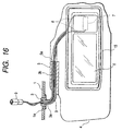
- the sunvisor incorporates a sunvisor body 4 formed into a rectangular-plate-like shape elongated in a lateral direction.
- the sunvisor body 4 is made of, for example, styrofoam.
- a recess 4a for securing a frame 15 (shown in Fig. 16) having a vanity mirror 6 and a vanity lamp 7 is formed in the front surface of the sunvisor body 4.
- a visor holder 5 having an insertion hole 5a for the stay 16 to be described later is joined to an upper portion of the sunvisor body 4.
- a cover (not shown) is provided for the frame 15. When the cover has been opened, a switch is switched on so that the vanity lamp 7 is turned on.
- the sunvisor body 4 is covered with an outer skin.
- the L-shape stay 16 incorporates a horizontal shaft portion 16a and a vertical shaft portion 16b.
- the horizontal shaft portion 16a of the stay 16 is inserted into the insertion hole 5a of the visor holder 5.
- the sunvisor body 4 is supported such that vertical movement of the sunvisor body 4 around the horizontal shaft is permitted.
- the vanity mirror 6 is locked by a lock spring or the like to prevent undesirable separation.
- a pair of bus bars 17 are insert-molded into the stay 16.
- Each of the male terminal portion 17a and 17b of the bus bars 17 projects over ends of the horizontal shaft portion 16a and the vertical shaft portion 16b for a predetermined length.
- the sunvisor-side connector 19 is locked by a lock spring or the like at a predetermined position of the insertion hole 5a to prevent separation.
- the male terminal portion 17a of the horizontal shaft portion 16a is automatically engaged to the female terminal 18 of the sunvisor-side connector 19.
- the sunvisor-side connector 19 which is able to rotate around the horizontal shaft permits the vertical movement of the sunvisor body 4. The rotation of the sunvisor-side connector 19 is absorbed because the electric wires 8 are twisted.
- Two register recesses 19a are formed in an end surface of the sunvisor-side connector 19. Moreover, two register projections 16c which are longer than the male terminal portion 17a and allowed to project over the male terminal portion 17a are formed on the end surface of the register projections 16a of the stay 16. When the register projections 16a are inserted into the insertion hole 5a, the register projections 16a are engaged to the register recesses 19a of the sunvisor-side connector 19.
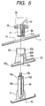
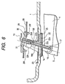
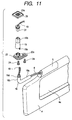
- a stay holder 22 which is joined to the roof panel 1 in the cabin incorporates a flange portion 22a which is made contact with the lower surface of the roof panel 1 and a holder portion 22b which is inserted into the joining hole 1a of the roof panel 1.
- the flange portion 22a is secured to the roof panel 1 with screws 24 by using screw washers 23 (see Fig. 6) made contact with the upper surface of the roof panel 1. Note that the flange portion 22a is covered with a cover 25.
- An insertion hole 22c into which the vertical shaft portion 16b of the stay 16 is inserted rotatively around the vertical shaft, is formed in the lower portion of the holder portion 22b of the stay holder 22.
- An engaging projection 22d for securing an outer groove 16d of the vertical shaft portion 16b when the vertical shaft portion 16b has been inserted to a predetermined depth is formed in the upper portion of the insertion hole 22c.
- the vertical shaft portion 16b is locked so that removal of the vertical shaft portion 16b from the insertion hole 22c is prevented.
- a thin sleeve portion 22f having the length which is substantially the same as that of the male terminal 17b projecting over the end surface of the vertical shaft portion 16b of the stay 26 is formed in an upper portion of the holder portion 22b of the stay holder 22.
- the sleeve portion 22f has four slits 22g formed at the same intervals in the circumferential direction of the sleeve portion 22f so that elasticity is imparted to the sleeve portion 22f.
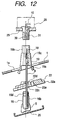
- a car-body-side connector 31 for accommodating a female terminal 30 to which the electric wire 10 extended from a mounted battery is connected is joined to a connector holder 29 joined to a car body member 28 in the roof panel 1 such that rotation of the car-body-side connector 31 around the vertical shaft is permitted.
- the car-body-side connector 31 which is capable of rotating around the vertical shaft, permits the longitudinal movement of the sunvisor body 4.
- the rotation of the car-body-side connector 31 can be absorbed when the electric wire 10 is twisted.
- register projections 31a are formed on the end surface of the car-body-side connector 31.
- Register recesses 16e are formed in the end surface of the vertical shaft portion 16b of the stay 16.
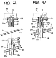
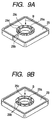
- the connector holder 29 has a cylindrical insertion hole portion 29a into which the car-body-side connector 31 is inserted.
- the insertion hole portion 29a has an outward-opened slit 29b into which the car-body-side connector 31 is inserted from a direction (from a side position) perpendicular to the axial direction.
- a semi-circular cut portions 29c are formed around the insertion hole portion 29a. The cut portions 29c are connected by a plurality of thin bridge portions 29d so that slight displacement of the insertion hole portion 29a in the direction perpendicular to the axial direction is permitted.
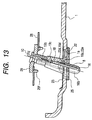
- the car-body member 28 has an insertion portion 28a formed by cutting upwards the three sides and by inwardly bending the leading ends of the three sides.
- the connector holder 29 is inserted through one of the portions of the insertion portion 28a (see an arrow A shown in Fig. 8B). Note that the connector holder 29 may be joined to the car-body member 28 with a snap portion 29f, as shown in Fig. 6.
- a rotation-stopping projection 31b projecting over the outer surface of the car-body-side connector 31 is formed on the side portion of the car-body-side connector 31.
- the rotation-stopping projection 31b is brought into contact with the two side surfaces 29e of the outward-opened slit 29b of the connector holder 29.
- undesirable rotation of the car-body-side connector 31 is stopped at the connector joining position.
- Fig. 7B when the car-body-side connector 31 has been inserted into the sleeve portion 22f of the stay holder 22, the car-body-side connector 31 is inserted into the sleeve portion 22f more inwards than the outer surface.
- contact with the two side surfaces 29e of the outward-opened slit 29b can be prevented. That is, the car-body-side connector 31 is able to freely rotate in the insertion hole portion 29a.
- the outward-opened slit 29b of the connector holder 29 also serves an insertion slit for inserting the car-body-side connector 31 into the insertion hole portion 29a from the direction perpendicular to the axial direction.
- the outward-opened shape is not required.
- the slit 29b may be omitted.
- the insertion hole portion 29a may be formed into a rectangular shape as a substitute for the cylindrical shape. In this case, a rectangular car-body-side connector 31 is inserted into the insertion hole portion 29a from the axial direction.
- the bus bars 17 is insert-molded in the stay 16
- the necessity of passing the electric wires 8 of the vanity lamp 7 through the L-shape stay 16 can be eliminated. Therefore, the operation required for the conventional technique to pass the electric wire can be omitted.
- the male terminal portion 17a of the bus bars 17 of the register projections 16a can automatically be engaged to the female terminal 18 of the sunvisor-side connector 19. Therefore, the operation required for the conventional technique to connect the connectors can be omitted.
- the register recesses 19a is formed in the sunvisor-side connector 19, the register projections 16c is formed in the horizontal shaft portion 16a of the stay 16 and the register projections 16c is engaged to the register recesses 19a when the horizontal shaft portion 16a is inserted into the insertion hole 5a of the visor holder 5. Therefore, the male terminal portion 17a of the horizontal shaft portion 16a of the stay 16 can smoothly be inserted into the female terminal 18 of the sunvisor-side connector 19. Since the register projections 16c is longer than the male terminal portion 17a and formed to project over the male terminal portion 17a, the register projections 16c serve as guards to prevent unintentional breakage of the male terminal portion 17a which has not been engaged.
- the car-body-side connector 31 is joined to the car body member 28 in the roof panel 1. Therefore, the operation for joining the stay holder 22 to the roof panel 1 can be performed such that the male terminal portion 17b of the bus bars 17 of the vertical shaft portion 16b of the stay 16 is automatically engaged to the female terminal 30 of the car-body-side connector 31. Therefore, the operation required for the conventional technique to connect the connectors can be omitted.
- the stay holder 22, which supports the vertical shaft portion 16b of the stay 16 is provided with the sleeve portion 22f having the length which is substantially the same as that of the male terminal portion 17b of the vertical shaft portion 16b.
- the sleeve portion 22f serves as a guard to prevent unintentional breakage of the male terminal portion 17b which has not been engaged. Since the axial-directional 22g is formed in the sleeve portion 22f, insertion of the car-body-side connector 31 can smoothly be performed.
- the register projection 31a is formed on the car-body-side connector 31.
- the register recesses 16e is formed in the vertical shaft portion 16b of the stay 16. Therefore, when the stay holder 22, which supports the vertical shaft portion 16b, is joined to the roof panel 1, the register recesses 16e is engaged to the register projections 31a. Therefore, the male terminal portion 17b of the vertical shaft portion 16b of the stay 16 can smoothly be engaged to the female terminal 30 of the car-body-side connector 31.
- the car-body-side connector 31 is inserted into the insertion hole portion 29a of the connector holder 29 provided for the car body member 28. Therefore, the car-body-side connector 31 can be joined to the connector holder 29 by a one-touch operation. Since the car-body-side connector 31 can be displaced in the direction perpendicular to the axial direction owing to the insertion hole portion 29a, an error from the male terminal portion 17a of the vertical shaft portion 16b of the stay 16 occurring when assembly is performed can be absorbed. As a result, the male terminal portion 17b of the vertical shaft portion 16b of the stay 16 can smoothly be engaged.
- the connector holder 29 When the connector holder 29 is simply inserted into the insertion portion 28a of the car body member 28, the connector holder 29 and the car-body-side connector 31 can be joined by the one-touch operation.
- the rotation-stopping projection 31b of the car-body-side connector 31 is brought into contact with the two side surfaces 29e of the outward-opened slit 29b of the insertion hole portion 29a of the connector holder 29. Therefore, unintentional rotation of the car-body-side connector 31 around the vertical shaft can be prevented before the male terminal portion 17b of the vertical shaft portion 16b of the stay 16 is engaged to the female terminal 30 of the car-body-side connector 31. Therefore, the male terminal portion 17b of the vertical shaft portion 16b of the stay 16 can smoothly be engaged.
- the outward-opened slit 29b also serves as the insertion slit for inserting the car-body-side connector 31 into the insertion hole portion 29a from the direction perpendicular to the axial direction. Therefore, the car-body-side connector 31 can easily and quickly be inserted into the connector holder 29.
- the wiring structure for a sunvisor according to the present invention has the structure that the bus bar is insert-molded into the L-shape stay. Therefore, the necessity of passing the electric wire of the vanity lamp through the L-shape stay can be eliminated. Therefore, the operation for passing the electric wire can be omitted.
- the sunvisor-side connector is joined to the visor holder of the sunvisor body (aspect 2). Therefore, the operation for inserting the horizontal shaft portion into the visor holder can be performed such that the male terminal portion of the bus bar of the horizontal shaft portion is automatically engaged to the female terminal of the sunvisor-side connector. Therefore, the operation for connecting the connectors can be omitted.
- the car-body-side connector is joined to the car-body member in the roof panel (aspect 3). Therefore, the operation for joining the stay holder to the roof panel can be performed such that the male terminal of the bus bar of the vertical shaft portion is automatically engaged to the female terminal of the car-body-side connector. Therefore, the operation for connecting the connectors can be omitted.
- the register recesses are formed in the sunvisor-side connector and the register projection is formed on the horizontal shaft portion (aspect 4). Therefore, the male terminal portion-of the horizontal shaft portion of the stay can smoothly be engaged to the female terminal of the sunvisor-side connector.
- the register projection is longer than the male terminal portion to project over the male terminal portion. Therefore, the register projection serves as the guard to prevent unintentional breakage of the male terminal portion before the male terminal portion is engaged.
- the sleeve portion having the length substantially the same as that of the male terminal portion of the vertical shaft portion of the stay is provided for the stay holder (aspect 5). Therefore, the sleeve portion serves as a guard for preventing unintentional breakage of the male terminal portion which has not been engaged. Since the axial-directional slit is formed in the sleeve portion, insertion of the car-body-side connector can smoothly be performed.
- Either of the register projection or the register recess is provided for the car-body-side connector and the other one of the register projection or the register recess is provided for the vertical shaft portion of the stay (aspect 6). Therefore, the male terminal portion of the vertical shaft portion can smoothly be inserted into the female terminal of the car-body-side connector.
- the connector holder having the insertion portion which can be displaced in the direction perpendicular to the axial direction is provided for the car-body member (aspect 7). Therefore, the car-body-side connector can be joined to the connector holder of the car-body member by the one-touch operation. Therefore, an error from the male terminal portion of the vertical shaft portion of the stay occurring when assembly is performed can be absorbed. Thus, the male terminal portion of the vertical shaft portion of the stay can smoothly be joined.
- the connector holder is inserted and joined to the insertion portion of the car-body member (aspect 8). Therefore, the connector holder and the car-body-side connector can be joined to the car-body member by the one-touch operation.
- the slit is formed in the insertion portion of the connector holder and the rotation-stopping projection is formed on the car-body-side connector (aspect 9). Therefore, unintentional rotation of the car-body-side connector around the vertical shaft can be prevented before the male terminal portion of the vertical shaft portion of the stay is engaged to the female terminal of the car-body-side connector. Therefore, the male terminal portion of the vertical shaft portion of the stay can smoothly be engaged.
- the slit also serves as the insertion slit for inserting the car-body-side connector into the car-body-side-connector insertion portion from the direction perpendicular to the axial direction (aspect 10). Therefore, the car-body-side connector can easily and quickly be inserted into the connector holder.
- the stay 16 is constituted by a pipe member. Similar to the conventional structure, a pair of electric wires 8 having ends connected to the vanity lamp 7 are passed through the stay 16. A male terminal 18 is connected to other ends of the electric wires 8 extended from the vertical shaft portion 16b of the stay 16.
- a stay holder 22 which is joined to the roof panel 1 in the cabin incorporates a flange portion 22a which is made contact with the lower surface of the roof panel 1, an insertion hole 22c into which the vertical shaft portion 16b of the stay 16 is inserted such that rotation of the vertical shaft portion 16b around the vertical shaft is permitted and an engaging recess 22e to which a sunvisor-side connector 19 to be described later is engaged.
- An engaging projection 22d for engaging an outer groove 16d of the vertical shaft portion 16b when the vertical shaft portion 16b has been inserted into a predetermined depth is formed in the upper portion of the insertion hole 22c.
- the vertical shaft portion 16b is locked in such a manner that removal of the vertical shaft portion 16b from the insertion hole 22c is prevented. Since the vertical shaft portion 16b of the stay 16 is inserted into the insertion hole 22c, the sunvisor body 4 is supported such that lateral movement (when the sunvisor is used) around the vertical shaft is permitted.
- An engaging claw 19a which is engaged to the engaging recess 22e of the stay holder 22 from an upper position so as to be integrated with the stay holder 22 is formed in the lower portion of the sunvisor-side connector 19. Moreover, a hood portion 19b into a car-body-side connector 31 to be described later is formed in the upper portion of the sunvisor-side connector 19.
- a cavity 19c for accommodating the female terminal 18 at another end of the electric wires 8 extended from the vertical shaft portion 16b of the stay 16 is formed in the sunvisor-side connector 19.
- the flange portion 22a of the stay holder 22 is secured to the roof panel 1 with screws 24 by using a screw washer 23 made contact with the upper surface of the roof panel 1 in a state in which the sunvisor-side connector 19 has been engaged. Note that the flange portion 22a is covered with a cover 25.
- the car-body-side connector 31 formed into a rectangular shape and arranged to accommodate a female terminal 30 to which the electric wire 10 extended from a battery mounted on the vehicle is connected is joined to a connector holder 29 joined to a car body member 28 in the roof panel 1.
- the female terminal portion 18 is automatically engaged to the female terminal 30 of the car-body-side connector 31 while the hood portion 19c of the sunvisor-side connector 19 is being inserted into the car-body-side connector 31. Note that the vertical movement of the sunvisor body 4 around the horizontal shaft and the longitudinal movement of the same around the vertical shaft are absorbed because the electric wires 8 are twisted.
- the connector holder 29 has an insertion hole portion 29a formed into a rectangular shape to receive the car-body-side connector 31 from the axial direction. Cut portions 29c are formed around the insertion hole portion 29a. The cut portions 29c are connected to one another by a plurality of thin-width bridge portion 29d so that slight displacement of the insertion hole portion 29a in the direction perpendicular to the axial direction is permitted.
- the car-body member 28 has an insertion portion 28a formed by cutting upwards the three sides and by inwardly bending the leading ends of the three sides.
- the connector holder 29 is inserted and joined from any one of the portions of the insertion portion 28a. Note that the connector holder 29 may be joined to the car body member 28 with a snap portion 29f, as shown in Fig. 13.
- the foregoing structure is arranged such that the sunvisor-side connector 19 is integrally engaged and joined to the stay holder 22.
- the necessity of holding the sunvisor-side connector 19 with the hands can be eliminated.
- the operation for joining the stay holder 22 to the roof panel 1 can be performed such that the sunvisor-side connector 19 is automatically joined to the car-body-side connector 31. Therefore, the operation for connecting the connectors can be omitted.
- the car-body-side connector 31 is simply inserted into the connector holder 29 of the car body member 28 so that joining is performed by a one-touch operation. Since the insertion portion 29a permits displacement of the car-body-side connector 31 in the direction perpendicular to the axial direction, an error from the sunvisor-side connector 19 occurring when assembly is performed can be absorbed. Therefore, the sunvisor-side connector 19 can smoothly be joined.
- joining can be performed by a one-touch operation.
- the wiring structure for a sunvisor according to the present invention is arranged such that the sunvisor-side connector is integrally joined to the stay holder.
- the necessity of holding the sunvisor-side connector with the hands can be eliminated.
- the operation for joining the stay holder to the roof panel can be performed such that the sunvisor-side connector is automatically joined to the car-body-side connector. As a result, the operation for connecting the connectors can be omitted.
- the connector holder for receiving and joining the car-body-side connector from the axial direction is provided for the car-body member (aspect 12). Therefore, the car-body-side connector can be joined to the connector holder of the car-body member by a one-touch operation. Moreover, the insertion portion permits displacement of the car-body-side connector in the direction perpendicular to the axial direction. Therefore, an error or the like from the sunvisor-side connector occurring when assembly is performed can be absorbed. Thus, the sunvisor-side connector can smoothly be joined.
- the connector holder is inserted and joined to the insertion portion of the car-body member (aspect 13).
- the connector holder and the car-body-side connector can be joined to the car-body member by a one-touch operation.
Landscapes
- Engineering & Computer Science (AREA)
- Mechanical Engineering (AREA)
- Details Of Connecting Devices For Male And Female Coupling (AREA)
Applications Claiming Priority (4)
| Application Number | Priority Date | Filing Date | Title |
|---|---|---|---|
| JP35955198A JP3629376B2 (ja) | 1998-12-17 | 1998-12-17 | サンバイザの配線構造 |
| JP35955398A JP3629378B2 (ja) | 1998-12-17 | 1998-12-17 | サンバイザの配線構造 |
| JP35955398 | 1998-12-17 | ||
| JP35955198 | 1998-12-17 |
Publications (2)
| Publication Number | Publication Date |
|---|---|
| EP1010556A2 true EP1010556A2 (de) | 2000-06-21 |
| EP1010556A3 EP1010556A3 (de) | 2002-11-13 |
Family
ID=26580985
Family Applications (1)
| Application Number | Title | Priority Date | Filing Date |
|---|---|---|---|
| EP99117896A Withdrawn EP1010556A3 (de) | 1998-12-17 | 1999-09-10 | Verkabelungsstruktur für Sonnenblende |
Country Status (2)
| Country | Link |
|---|---|
| US (1) | US6368114B1 (de) |
| EP (1) | EP1010556A3 (de) |
Cited By (6)
| Publication number | Priority date | Publication date | Assignee | Title |
|---|---|---|---|---|
| FR2814710A1 (fr) * | 2000-09-29 | 2002-04-05 | Grupo Antolin Vosges Sas | Dispositif d'alimentation electrique pour pare soleil de vehicule |
| EP1219481A1 (de) * | 2000-12-25 | 2002-07-03 | Yazaki Corporation | Steck-Verbindungseinrichtung für Zusatzkomponente |
| WO2003095253A1 (es) * | 2002-05-07 | 2003-11-20 | Grupo Antolin-Ingenieria, S.A. | Parasol con brazo conductor para vehículos |
| CN102734708A (zh) * | 2012-06-09 | 2012-10-17 | 李绍和 | 组合式led装饰镜灯 |
| CN103786553A (zh) * | 2013-12-05 | 2014-05-14 | 富卓汽车内饰(安徽)有限公司 | 一种汽车用遮阳板总成 |
| EP2813386A1 (de) * | 2013-06-14 | 2014-12-17 | Grupo Antolin-Ingenieria, S.A. | Arm für eine Sonnenblende, Sonnenblende und Verfahren zur Herstellung eines Arms für eine Sonnenblende |
Families Citing this family (14)
| Publication number | Priority date | Publication date | Assignee | Title |
|---|---|---|---|---|
| US6676129B2 (en) * | 2001-04-12 | 2004-01-13 | Lear Corporation | Sun visor arm connection assembly and arrangement |
| DE10208106B4 (de) * | 2002-02-26 | 2013-04-11 | Roof Systems Germany Gmbh | Baugruppe für eine Fahrzeugtür |
| US6790066B1 (en) * | 2002-11-27 | 2004-09-14 | Western Digital Technologies, Inc. | Apparatus for securing a cable assembly within an enclosed electronic system |
| ATE320943T1 (de) * | 2003-11-11 | 2006-04-15 | Antolin Grupo Ing Sa | Sicherheitshalterung für einen innenspiegel eines fahrzeugs |
| ITMO20040005A1 (it) * | 2004-01-13 | 2004-04-13 | Meta System Spa | Gruppo di rilevamento di ostacoli nelle vicinanze di veicoli |
| KR100971692B1 (ko) | 2008-10-16 | 2010-07-22 | 주식회사 용산 | 선바이저용 스위치 |
| JP5467918B2 (ja) * | 2010-04-23 | 2014-04-09 | 共和産業株式会社 | 車両用サンバイザ |
| US8556325B2 (en) | 2011-09-20 | 2013-10-15 | Irvin Automotive Products, Inc. | Sliding visor |
| CN104325865B (zh) * | 2014-08-29 | 2016-06-29 | 长安马自达汽车有限公司 | 带支架的车用遮阳板转轴总成及其加工方法 |
| US10737559B2 (en) | 2014-12-16 | 2020-08-11 | Irvin Automotive Products, LLC | Visor |
| US20170240103A1 (en) | 2016-02-23 | 2017-08-24 | Motus Integrated Technologies | Vehicle sun visor assembly having an electrical system |
| US10688850B2 (en) | 2018-03-13 | 2020-06-23 | Irvin Automotive Products, LLC | Sliding visor |
| US10870337B2 (en) | 2019-02-28 | 2020-12-22 | Irvin Automotive Products, LLC | Thin visor |
| US10864804B2 (en) | 2019-02-28 | 2020-12-15 | Irvin Automotive Products, LLC | Sliding thin visor |
Family Cites Families (15)
| Publication number | Priority date | Publication date | Assignee | Title |
|---|---|---|---|---|
| US1157026A (en) * | 1911-10-20 | 1915-10-19 | William F Meschenmoser | Plug-switch. |
| US2983895A (en) * | 1957-12-11 | 1961-05-09 | Reeves Instrument Corp | Coaxial jack plug |
| DE2703447C3 (de) * | 1977-01-28 | 1979-09-06 | Gebr. Happich Gmbh, 5600 Wuppertal | Sonnenblende für Fahrzeuge |
| US4472010A (en) * | 1983-01-31 | 1984-09-18 | Parnello Nicholas G | Twist-inhibiting appliance for connecting a cable of a telephone set or the like |
| DE3601762C1 (de) * | 1986-01-22 | 1987-04-30 | Happich Gmbh Gebr | Sonnenblende fuer Fahrzeuge |
| DE3713425A1 (de) * | 1987-04-22 | 1988-11-03 | Happich Gmbh Gebr | Gegenlagerboeckchen fuer fahrzeugsonnenblenden |
| DE3916560A1 (de) * | 1989-05-20 | 1990-11-22 | Zipperle Eugen Gmbh & Co Kg | Sonnenblende fuer kraftfahrzeuge |
| FR2659596B1 (fr) * | 1990-03-13 | 1992-12-11 | Rockwell Abs France | Bras de support coude pour pare-soleil alimente electriquement par des conducteurs. |
| DE4135719C1 (de) * | 1991-10-30 | 1992-10-22 | Gebr. Happich Gmbh, 5600 Wuppertal, De | |
| DE19608566A1 (de) * | 1996-03-06 | 1997-12-04 | Hirschmann Richard Gmbh | Blendschutzvorrichtung |
| DE19647918A1 (de) * | 1996-11-20 | 1998-05-28 | Happich Gmbh Gebr | Sonnenblende für Fahrzeuge |
| JP3865273B2 (ja) * | 1997-09-26 | 2007-01-10 | 矢崎総業株式会社 | ルーフモジュール構造 |
| DE19754533A1 (de) * | 1997-12-09 | 1999-06-10 | Johnson Contr Interiors Gmbh | Sonnenblendenachse |
| US6139083A (en) * | 1998-04-24 | 2000-10-31 | Lear-Donnelly Overhead Systems, Llc | Sliding core visor |
| JP3629377B2 (ja) * | 1998-12-17 | 2005-03-16 | 株式会社オートネットワーク技術研究所 | サンバイザの照明構造 |
-
1999
- 1999-09-07 US US09/390,320 patent/US6368114B1/en not_active Expired - Fee Related
- 1999-09-10 EP EP99117896A patent/EP1010556A3/de not_active Withdrawn
Non-Patent Citations (1)
| Title |
|---|
| None |
Cited By (8)
| Publication number | Priority date | Publication date | Assignee | Title |
|---|---|---|---|---|
| FR2814710A1 (fr) * | 2000-09-29 | 2002-04-05 | Grupo Antolin Vosges Sas | Dispositif d'alimentation electrique pour pare soleil de vehicule |
| EP1219481A1 (de) * | 2000-12-25 | 2002-07-03 | Yazaki Corporation | Steck-Verbindungseinrichtung für Zusatzkomponente |
| US6558193B2 (en) | 2000-12-25 | 2003-05-06 | Yazaki Corporation | Connector fitting structure for auxiliary component |
| WO2003095253A1 (es) * | 2002-05-07 | 2003-11-20 | Grupo Antolin-Ingenieria, S.A. | Parasol con brazo conductor para vehículos |
| US7108309B2 (en) | 2002-05-07 | 2006-09-19 | Grupo Antolin-Ingenieria, S.A. | Sun visor with conducting arm for vehicles |
| CN102734708A (zh) * | 2012-06-09 | 2012-10-17 | 李绍和 | 组合式led装饰镜灯 |
| EP2813386A1 (de) * | 2013-06-14 | 2014-12-17 | Grupo Antolin-Ingenieria, S.A. | Arm für eine Sonnenblende, Sonnenblende und Verfahren zur Herstellung eines Arms für eine Sonnenblende |
| CN103786553A (zh) * | 2013-12-05 | 2014-05-14 | 富卓汽车内饰(安徽)有限公司 | 一种汽车用遮阳板总成 |
Also Published As
| Publication number | Publication date |
|---|---|
| EP1010556A3 (de) | 2002-11-13 |
| US6368114B1 (en) | 2002-04-09 |
Similar Documents
| Publication | Publication Date | Title |
|---|---|---|
| EP1010556A2 (de) | Verkabelungsstruktur für Sonnenblende | |
| US6270240B1 (en) | Structure for illuminating sunvisor | |
| US5066878A (en) | Small-sized electric motor housing circuit breaker | |
| US5454737A (en) | Relay connector | |
| US5430624A (en) | Mounting structure for a vanity mirror | |
| JPH08192680A (ja) | 電動リモートコントロールミラーにおける駆動ユニットとハーネスとの接続構造 | |
| EP1219481B1 (de) | Steck-Verbindungseinrichtung für Zusatzkomponente | |
| US6354843B1 (en) | Electrical connector for a vehicle body side having engaging and recess portions for connection | |
| US6616475B2 (en) | Electric wire connecting structure of lamp unit | |
| US6053758A (en) | Door trim connector connecting structure | |
| EP0840402B1 (de) | Verbinder | |
| US6159019A (en) | Mounting structure for connector for vehicle and method of mounting the same | |
| US6287142B1 (en) | Bracket for attaching sun visor provided with electric equipment onto vehicle body | |
| US6347959B2 (en) | Bracket for attaching interior equipment | |
| KR19980032404A (ko) | 스위치 접속 구조 | |
| EP1695850B1 (de) | Haltekonsolen-Struktur | |
| US5238214A (en) | Holding device for a connector associated with an electrically controlled automotive mirror | |
| US20010002170A1 (en) | Rear combination lamp | |
| US6406087B2 (en) | Bracket for attaching interior equipment | |
| US5713754A (en) | Fitting structure of movable connector | |
| JP3747964B2 (ja) | 調心コネクタ | |
| JPH118005A (ja) | 開閉扉付き電気コネクタ | |
| JP2589762Y2 (ja) | ヒューズの係止構造 | |
| US3453578A (en) | Electrical plug connector | |
| JP3629378B2 (ja) | サンバイザの配線構造 |
Legal Events
| Date | Code | Title | Description |
|---|---|---|---|
| PUAI | Public reference made under article 153(3) epc to a published international application that has entered the european phase |
Free format text: ORIGINAL CODE: 0009012 |
|
| AK | Designated contracting states |
Kind code of ref document: A2 Designated state(s): AT BE CH CY DE DK ES FI FR GB GR IE IT LI LU MC NL PT SE |
|
| AX | Request for extension of the european patent |
Free format text: AL;LT;LV;MK;RO;SI |
|
| PUAL | Search report despatched |
Free format text: ORIGINAL CODE: 0009013 |
|
| AK | Designated contracting states |
Kind code of ref document: A3 Designated state(s): AT BE CH CY DE DK ES FI FR GB GR IE IT LI LU MC NL PT SE |
|
| AX | Request for extension of the european patent |
Free format text: AL;LT;LV;MK;RO;SI |
|
| RIC1 | Information provided on ipc code assigned before grant |
Free format text: 7B 60J 3/00 A, 7B 60J 3/02 B |
|
| RAP1 | Party data changed (applicant data changed or rights of an application transferred) |
Owner name: SUMITOMO ELECTRIC INDUSTRIES, LTD. Owner name: AUTONETWORKS TECHNOLOGIES, LTD. Owner name: SUMITOMO WIRING SYSTEMS, LTD. |
|
| AKX | Designation fees paid | ||
| REG | Reference to a national code |
Ref country code: DE Ref legal event code: 8566 |
|
| STAA | Information on the status of an ep patent application or granted ep patent |
Free format text: STATUS: THE APPLICATION IS DEEMED TO BE WITHDRAWN |
|
| 18D | Application deemed to be withdrawn |
Effective date: 20030514 |