EP1010583A2 - Dispositif électronique - Google Patents
Dispositif électronique Download PDFInfo
- Publication number
- EP1010583A2 EP1010583A2 EP99123265A EP99123265A EP1010583A2 EP 1010583 A2 EP1010583 A2 EP 1010583A2 EP 99123265 A EP99123265 A EP 99123265A EP 99123265 A EP99123265 A EP 99123265A EP 1010583 A2 EP1010583 A2 EP 1010583A2
- Authority
- EP
- European Patent Office
- Prior art keywords
- housing part
- unit
- electronic device
- capacitor unit
- capacitor
- Prior art date
- Legal status (The legal status is an assumption and is not a legal conclusion. Google has not performed a legal analysis and makes no representation as to the accuracy of the status listed.)
- Granted
Links
Images

Classifications
-
- B—PERFORMING OPERATIONS; TRANSPORTING
- B60—VEHICLES IN GENERAL
- B60R—VEHICLES, VEHICLE FITTINGS, OR VEHICLE PARTS, NOT OTHERWISE PROVIDED FOR
- B60R16/00—Electric or fluid circuits specially adapted for vehicles and not otherwise provided for; Arrangement of elements of electric or fluid circuits specially adapted for vehicles and not otherwise provided for
- B60R16/02—Electric or fluid circuits specially adapted for vehicles and not otherwise provided for; Arrangement of elements of electric or fluid circuits specially adapted for vehicles and not otherwise provided for electric constitutive elements
- B60R16/023—Electric or fluid circuits specially adapted for vehicles and not otherwise provided for; Arrangement of elements of electric or fluid circuits specially adapted for vehicles and not otherwise provided for electric constitutive elements for transmission of signals between vehicle parts or subsystems
- B60R16/0239—Electronic boxes
-
- B—PERFORMING OPERATIONS; TRANSPORTING
- B60—VEHICLES IN GENERAL
- B60L—PROPULSION OF ELECTRICALLY-PROPELLED VEHICLES; SUPPLYING ELECTRIC POWER FOR AUXILIARY EQUIPMENT OF ELECTRICALLY-PROPELLED VEHICLES; ELECTRODYNAMIC BRAKE SYSTEMS FOR VEHICLES IN GENERAL; MAGNETIC SUSPENSION OR LEVITATION FOR VEHICLES; MONITORING OPERATING VARIABLES OF ELECTRICALLY-PROPELLED VEHICLES; ELECTRIC SAFETY DEVICES FOR ELECTRICALLY-PROPELLED VEHICLES
- B60L1/00—Supplying electric power to auxiliary equipment of vehicles
- B60L1/003—Supplying electric power to auxiliary equipment of vehicles to auxiliary motors, e.g. for pumps, compressors
Definitions
- the invention relates to an electronic device for a motor vehicle, which in a two-part housing one for switching high currents has trained electronics unit, whereby to suppress the thereby caused interference signals a capacitor unit in the housing is arranged.
- Control devices which, in addition to the control electronics, also have a Power output stage for controlling a motor vehicle Actuator included.
- actuating the actuator such as an electric motor for window regulators or for realizing a Valve strokes in a motor vehicle are determined by the power output stages high currents provided.
- high currents provided.
- timed control of the actuator become interference signals by switching the high currents inside of the control unit, the level of which is many times greater than the level of the signals that the control electronics process.
- the signals of the control device by this electromagnetic Interfering signals affected.
- Capacitors electrically connected which compensate for the interference signals.
- Both the power electronics and the capacitors generate in Operation a high heat loss, which through the housing to the environment is delivered.
- the invention has for its object an electronic device specify which is easy to manufacture, and which of the electronic Circuits generate heat the function of the electronic Circuits not affected.
- the object is achieved in that the large area Capacitor unit and the electronics unit spatially separated a carrier substrate are arranged, the capacitor unit thermally with a first area and the electronics unit thermally is connected to a second region of a first housing part.
- the advantage of the invention is that the two, generating waste heat Compenents transfer their heat to different areas of the same Submit part of the housing, whereby a rapid heat dissipation via the entire area of the first housing part is guaranteed. With that the best possible heat exchange between electronics and the housing part achieved. Due to this heat distribution, the use of an as Heat sink designed second housing part can be dispensed with.
- the capacitor unit is on one, the first housing part facing surface of the carrier substrate arranged while the electronics unit on a surface facing away from the housing part of the carrier substrate is arranged, wherein the first region of the first Housing part rests on the capacitor unit, while the second area of the first housing part almost completely on the, the first Housing part facing surface rests.
- the components forming the electronics unit are on the Surface mounted surface facing away from the first housing part. Also the electrical connection of the capacitor unit or a plug unit the electronic unit can be used for surface mounting.
- the first area of the first housing part is for positive reception of the capacitor unit on its inner surface adapted the outer contour of the capacitor unit.
- the first housing part Especially when using commercially available capacitor cells, has the inner surface of the first region of the first housing part Corresponding semicircular outer contour of the capacitor elements Deepening. With this arrangement, the first housing part lies directly on the capacitor cells, which creates direct thermal contact.
- Thermal conductive adhesive layer arranged between the capacitor unit and the first housing part. This thermal adhesive layer transfers not only the heat generated by the condenser unit to the first area of the first housing part, but also compensates for the structural tolerance of the capacitor cells inside the housing, which is caused by the Fixation on the first housing part is still supported.
- the connector elements for establishing an electrical connection with the capacitor unit or the electronic unit on the carrier substrate are.
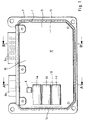
- FIG. 1 is the basic structure of the device according to the invention shown how it is used to control an electric motor, the sets the valve lift of an air intake valve of an internal combustion engine.
- the electronic device consists of two housing parts 1 and 2.
- Two Plug units 6a and 6b protrude from the housing 1, 2.
- a capacitor unit consisting of three capacitor cells 4a to 4c arranged.
- a Zener diode 5 is provided in order to prevent current peaks and thus protect the electronic circuit from destruction.
- the first housing part 1 has a thermal connection the electronics two areas on the first area 12 of the first housing part 1 extends along the entire extent of the capacitor cells 4a, 4b, 4c from the housing edge 14 to the end of the capacitor unit 4a, 4b, 4c. This is parallel to the connector device 6a a second area 13 of the housing part 1.
- section A-A ' is between the housing parts 1 and 2, the connector unit 6b closely arranged.
- the plug-in unit 6b has several as a stamped and bent part trained plug elements 7, which are guided to the outside and serve to connect a mating connector.
- Inside the housing 15 are the Connector elements 7 soldered to a circuit board 3, which between the two housing parts 1 and 2 is mounted. Set the connector elements 7 thus an electrical connection with a control electronics 9, which in Dependency of the process to be monitored control signals for a power output module 8 generated.
- the control electronics 9 is on one side 16 of the circuit board 3 opposite arranged to the three capacitor cells 4a, 4b, 4c and the Zener diode 5, which are attached to the second side 17 of the circuit board 3.
- the capacitor cells 4a, 4b, 4c engage positively in recesses 10 a, which on the inside of the first region 12 of the second housing part 1 are formed. In the present case they are Recesses 10 formed semicircular. This way, a direct thermal contact of the capacitor cells 4a, 4b, 4c with the first housing part 1 manufactured.
- the circuit board 3 is the first housing part 1 and the connector unit 6b worn. Between the individual capacitor cells 4a, 4b, 4c and each recess 10 is a heat-conducting adhesive layer 11 for improved Heat dissipation arranged.
- connection elements 7 also formed as a sheet metal part with the Printed circuit board 3 connected.
- the plug element 6 a serves for connection to a mating connector, which is the energy supply of the this power electronics located on the circuit board 3 8 guaranteed.
- the connector element 6a from the power amplifier electronics 8 upon request by the control electronics 9 provided switching voltage or currents for the electric motor generated and transferred to this.
- the power amplifier electronics 8 is on the surface facing the second housing part 16 of the circuit board 3 arranged.
- the second area 13 of the first housing part 1 is flat in this area on the opposite side 17 of the circuit board 3 and thus forms a direct thermal contact.
- Both the components the control electronics 9 and the components of the power amplifier electronics 8, as well as the connector elements 7 and the electrical connection of the capacitors 4a, 4b, 4c are on the second housing part 2 facing surface 16 of the circuit board 3 by means of the known Surface mounted SMD technology.
Landscapes
- Engineering & Computer Science (AREA)
- Mechanical Engineering (AREA)
- Power Engineering (AREA)
- Transportation (AREA)
- Shielding Devices Or Components To Electric Or Magnetic Fields (AREA)
- Cooling Or The Like Of Electrical Apparatus (AREA)
- Details Of Connecting Devices For Male And Female Coupling (AREA)
Applications Claiming Priority (4)
| Application Number | Priority Date | Filing Date | Title |
|---|---|---|---|
| DE19857824 | 1998-12-15 | ||
| DE19857824 | 1998-12-15 | ||
| DE19919098 | 1999-04-27 | ||
| DE19919098A DE19919098A1 (de) | 1998-12-15 | 1999-04-27 | Elektronische Einrichtung |
Publications (3)
| Publication Number | Publication Date |
|---|---|
| EP1010583A2 true EP1010583A2 (fr) | 2000-06-21 |
| EP1010583A3 EP1010583A3 (fr) | 2003-11-05 |
| EP1010583B1 EP1010583B1 (fr) | 2005-04-20 |
Family
ID=26050767
Family Applications (1)
| Application Number | Title | Priority Date | Filing Date |
|---|---|---|---|
| EP99123265A Expired - Lifetime EP1010583B1 (fr) | 1998-12-15 | 1999-11-29 | Dispositif électronique |
Country Status (1)
| Country | Link |
|---|---|
| EP (1) | EP1010583B1 (fr) |
Cited By (3)
| Publication number | Priority date | Publication date | Assignee | Title |
|---|---|---|---|---|
| EP1544043A1 (fr) * | 2003-12-17 | 2005-06-22 | Yazaki Corporation | Boítier de connexion électrique |
| EP1387606A3 (fr) * | 2002-07-30 | 2008-01-02 | Hitachi, Ltd. | Dispositing de contrôle dans un véhicule |
| WO2017108735A1 (fr) * | 2015-12-21 | 2017-06-29 | Robert Bosch Gmbh | Système électronique d'entraînement pour un entraînement électrique dans un véhicule |
Family Cites Families (4)
| Publication number | Priority date | Publication date | Assignee | Title |
|---|---|---|---|---|
| DE3440756A1 (de) * | 1984-11-08 | 1986-05-07 | CEAG Licht- und Stromversorgungstechnik GmbH, 6800 Mannheim | Stromversorgungsgeraet |
| US5016139A (en) * | 1989-09-06 | 1991-05-14 | Whelen Technologies, Inc. | Electronic power supply with enhanced heat transfer characteristics |
| US5297025A (en) * | 1992-10-28 | 1994-03-22 | Onan Corporation | Power supply assembly |
| DE4240755A1 (de) * | 1992-12-03 | 1994-06-16 | Siemens Ag | Steuergerät, insbesondere für ein Kraftfahrzeug |
-
1999
- 1999-11-29 EP EP99123265A patent/EP1010583B1/fr not_active Expired - Lifetime
Non-Patent Citations (1)
| Title |
|---|
| None |
Cited By (3)
| Publication number | Priority date | Publication date | Assignee | Title |
|---|---|---|---|---|
| EP1387606A3 (fr) * | 2002-07-30 | 2008-01-02 | Hitachi, Ltd. | Dispositing de contrôle dans un véhicule |
| EP1544043A1 (fr) * | 2003-12-17 | 2005-06-22 | Yazaki Corporation | Boítier de connexion électrique |
| WO2017108735A1 (fr) * | 2015-12-21 | 2017-06-29 | Robert Bosch Gmbh | Système électronique d'entraînement pour un entraînement électrique dans un véhicule |
Also Published As
| Publication number | Publication date |
|---|---|
| EP1010583B1 (fr) | 2005-04-20 |
| EP1010583A3 (fr) | 2003-11-05 |
Similar Documents
| Publication | Publication Date | Title |
|---|---|---|
| EP0941642B1 (fr) | Support pour circuit integre | |
| DE10056832B4 (de) | Halbleiterbauteil-Moduleinheit | |
| DE102007014789B3 (de) | Anordnung mindestens eines Leistungshalbleitermoduls und einer Leiterplatte und Leistungshalbleitermodul | |
| EP0588793B1 (fr) | Boitier pour composants electroniques d'automobile | |
| DE102008012570B4 (de) | Leistungshalbleitermodul-System, Leistungshalbleitermodulanordnung und Verfahren zur Herstellung einer Leistungshalbleitermodulanordnung | |
| DE69106615T2 (de) | Lageweise zusammengebaute Steckbuchsenleiste mit integraler Erdabschirmung. | |
| EP1148602B1 (fr) | Dispositif limiteur de surtensions | |
| DE102013100701B4 (de) | Halbleitermodulanordnung und verfahren zur herstellung einer halbleitermodulanordnung | |
| DE19518522C2 (de) | Steuergerät für ein Kraftfahrzeug | |
| EP0685939B1 (fr) | Commutateur électronique de puissance pour des véhicules automobiles | |
| WO1993009656A1 (fr) | Appareil electrique, en particulier appareil de connexion et de commande pour vehicules automobiles | |
| EP1010582A2 (fr) | Dispositif électronique | |
| EP3482611B1 (fr) | Système et procédé de connexion à la masse d'une carte de circuit imprimé sur un boîtier d'un appareil électrique | |
| DE10340297B4 (de) | Verbindugsanordnung zur Verbindung von aktiven und passiven elektrischen und elektronischen Bauelementen | |
| DE10113912A1 (de) | Elektronische Vorrichtung | |
| DE102017123109B4 (de) | Leistungselektronikmodul | |
| EP1010583B1 (fr) | Dispositif électronique | |
| DE10262012A1 (de) | Speichermodul mit einer Wärmeableiteinrichtung | |
| DE69917923T2 (de) | Gehaüse für eine leiterplatte zur horizontalen oder vertikalen montage | |
| DE10123198A1 (de) | Anordnung aus einem Gehäuse und einem Schaltungsträger | |
| DE60031199T2 (de) | Verbesserungen an elektrischen Schaltungen | |
| EP0058759A2 (fr) | Appareil de contrôle fabriqué en construction modulaire | |
| DE19919098A1 (de) | Elektronische Einrichtung | |
| EP1864557B1 (fr) | Procede de production d'un appareil electronique, et appareil electronique | |
| EP0941643B1 (fr) | Socle pour circuit integre |
Legal Events
| Date | Code | Title | Description |
|---|---|---|---|
| PUAI | Public reference made under article 153(3) epc to a published international application that has entered the european phase |
Free format text: ORIGINAL CODE: 0009012 |
|
| AK | Designated contracting states |
Kind code of ref document: A2 Designated state(s): AT BE CH CY DE DK ES FI FR GB GR IE IT LI LU MC NL PT SE |
|
| AX | Request for extension of the european patent |
Free format text: AL;LT;LV;MK;RO;SI |
|
| RAP1 | Party data changed (applicant data changed or rights of an application transferred) |
Owner name: SIEMENS AKTIENGESELLSCHAFT |
|
| PUAL | Search report despatched |
Free format text: ORIGINAL CODE: 0009013 |
|
| AK | Designated contracting states |
Kind code of ref document: A3 Designated state(s): AT BE CH CY DE DK ES FI FR GB GR IE IT LI LU MC NL PT SE |
|
| AX | Request for extension of the european patent |
Extension state: AL LT LV MK RO SI |
|
| 17P | Request for examination filed |
Effective date: 20040419 |
|
| AKX | Designation fees paid |
Designated state(s): DE FR GB |
|
| GRAP | Despatch of communication of intention to grant a patent |
Free format text: ORIGINAL CODE: EPIDOSNIGR1 |
|
| GRAS | Grant fee paid |
Free format text: ORIGINAL CODE: EPIDOSNIGR3 |
|
| GRAA | (expected) grant |
Free format text: ORIGINAL CODE: 0009210 |
|
| AK | Designated contracting states |
Kind code of ref document: B1 Designated state(s): DE FR GB |
|
| REG | Reference to a national code |
Ref country code: GB Ref legal event code: FG4D Free format text: NOT ENGLISH |
|
| REG | Reference to a national code |
Ref country code: IE Ref legal event code: FG4D Free format text: LANGUAGE OF EP DOCUMENT: GERMAN |
|
| REF | Corresponds to: |
Ref document number: 59911933 Country of ref document: DE Date of ref document: 20050525 Kind code of ref document: P |
|
| GBT | Gb: translation of ep patent filed (gb section 77(6)(a)/1977) |
Effective date: 20050520 |
|
| PLBE | No opposition filed within time limit |
Free format text: ORIGINAL CODE: 0009261 |
|
| STAA | Information on the status of an ep patent application or granted ep patent |
Free format text: STATUS: NO OPPOSITION FILED WITHIN TIME LIMIT |
|
| ET | Fr: translation filed | ||
| 26N | No opposition filed |
Effective date: 20060123 |
|
| REG | Reference to a national code |
Ref country code: FR Ref legal event code: TP |
|
| REG | Reference to a national code |
Ref country code: GB Ref legal event code: 732E Free format text: REGISTERED BETWEEN 20110825 AND 20110831 |
|
| PGFP | Annual fee paid to national office [announced via postgrant information from national office to epo] |
Ref country code: GB Payment date: 20121120 Year of fee payment: 14 |
|
| GBPC | Gb: european patent ceased through non-payment of renewal fee |
Effective date: 20131129 |
|
| PG25 | Lapsed in a contracting state [announced via postgrant information from national office to epo] |
Ref country code: GB Free format text: LAPSE BECAUSE OF NON-PAYMENT OF DUE FEES Effective date: 20131129 |
|
| REG | Reference to a national code |
Ref country code: FR Ref legal event code: PLFP Year of fee payment: 17 |
|
| PGFP | Annual fee paid to national office [announced via postgrant information from national office to epo] |
Ref country code: DE Payment date: 20151130 Year of fee payment: 17 |
|
| PGFP | Annual fee paid to national office [announced via postgrant information from national office to epo] |
Ref country code: FR Payment date: 20151119 Year of fee payment: 17 |
|
| REG | Reference to a national code |
Ref country code: DE Ref legal event code: R119 Ref document number: 59911933 Country of ref document: DE |
|
| REG | Reference to a national code |
Ref country code: FR Ref legal event code: ST Effective date: 20170731 |
|
| PG25 | Lapsed in a contracting state [announced via postgrant information from national office to epo] |
Ref country code: FR Free format text: LAPSE BECAUSE OF NON-PAYMENT OF DUE FEES Effective date: 20161130 |
|
| PG25 | Lapsed in a contracting state [announced via postgrant information from national office to epo] |
Ref country code: DE Free format text: LAPSE BECAUSE OF NON-PAYMENT OF DUE FEES Effective date: 20170601 |