EP1010652A1 - Vorrichtung zum Drucken, Lagern und Ausgeben von Gutscheinen - Google Patents
Vorrichtung zum Drucken, Lagern und Ausgeben von Gutscheinen Download PDFInfo
- Publication number
- EP1010652A1 EP1010652A1 EP98403157A EP98403157A EP1010652A1 EP 1010652 A1 EP1010652 A1 EP 1010652A1 EP 98403157 A EP98403157 A EP 98403157A EP 98403157 A EP98403157 A EP 98403157A EP 1010652 A1 EP1010652 A1 EP 1010652A1
- Authority
- EP
- European Patent Office
- Prior art keywords
- media
- presenting device
- accordance
- pair
- feed
- Prior art date
- Legal status (The legal status is an assumption and is not a legal conclusion. Google has not performed a legal analysis and makes no representation as to the accuracy of the status listed.)
- Granted
Links
- 238000007599 discharging Methods 0.000 title claims description 4
- 230000007246 mechanism Effects 0.000 title description 10
- 210000000038 chest Anatomy 0.000 claims abstract description 11
- 239000000463 material Substances 0.000 claims description 13
- 238000012986 modification Methods 0.000 description 2
- 230000004048 modification Effects 0.000 description 2
- 230000000712 assembly Effects 0.000 description 1
- 238000000429 assembly Methods 0.000 description 1
- 210000003195 fascia Anatomy 0.000 description 1
- 230000002452 interceptive effect Effects 0.000 description 1
- 239000010813 municipal solid waste Substances 0.000 description 1
- 238000010926 purge Methods 0.000 description 1
- 230000001960 triggered effect Effects 0.000 description 1
Images



Classifications
-
- B—PERFORMING OPERATIONS; TRANSPORTING
- B65—CONVEYING; PACKING; STORING; HANDLING THIN OR FILAMENTARY MATERIAL
- B65H—HANDLING THIN OR FILAMENTARY MATERIAL, e.g. SHEETS, WEBS, CABLES
- B65H29/00—Delivering or advancing articles from machines; Advancing articles to or into piles
- B65H29/006—Winding articles into rolls
- B65H29/008—Winding single articles into single rolls
-
- B—PERFORMING OPERATIONS; TRANSPORTING
- B65—CONVEYING; PACKING; STORING; HANDLING THIN OR FILAMENTARY MATERIAL
- B65H—HANDLING THIN OR FILAMENTARY MATERIAL, e.g. SHEETS, WEBS, CABLES
- B65H15/00—Overturning articles
- B65H15/004—Overturning articles employing rollers
Definitions
- This invention relates to receipt printing and handling devices and, more particularly, to a receipt printing, storage and presenting mechanism for printing a plurality of transactions upon a continuous web, temporarily storing the receipt web, and thereafter discharging the receipt web at an angle to the normal discharge direction.
- Retail establishments usually print receipts of the sales transactions upon a supply roll of paper. Very often, a plurality of transactions causes the printing of a lengthy receipt document. The long document presents an unwieldy and unmanageable web that is both unsightly and cumbersome to handle. The lengthy receipt web often drapes awkwardly from the print register, interfering with the entering of additional transactions and summing of the final receipt total.
- the present invention seeks to provide a device that captures and temporarily stores a lengthy receipt web, as the transactions are printed and totalled, and the web is cut.
- the device then rotates through an angle of between approximately 0 to 90 degrees (preferably 90 degrees) from the normal web discharge direction, and issues the receipt.
- the apparatus may be oriented to allow rotation to the left or to the right, providing a presentation field of 180 degrees. In this manner, the front of a register is not encumbered by a long, suspended, receipt web.
- a presenting mechanism that stores and then discharges a printed receipt, label, ticket, or form at an angle to the issuing direction.
- the mechanism comprises an overflow bucket, of generally oval shape, that is disposed adjacent the exit slot of a receipt printer.
- the overflow bucket is mounted upon a rotatable assembly.
- the receipt is dispersed as a continuous web from the exit slot of the receipt printer. It then enters the overflow bucket through an entrance guide.
- a sensor disposed adjacent the entrance guide senses the web of paper and triggers a motor that drives a pair of teed rollers connected thereto by a gear train. The same sensor is used to detect the trailing edge of the receipt, in order to detect jams as well as to determine that the receipt has been successfully discharged.
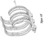
- the feed rollers push the paper web onto a rib-cage mandrel disposed in the overflow bucket.
- the rib-cage mandrel supports the paper as it is stored within the bucket, and allows the web to flow smoothly thereupon.
- the feed rollers Upon discharge from the overflow bucket, the feed rollers reverse direction and push the paper back out through the entrance guide.
- the feed rollers are mounted on a gear plate that rotates and causes the discharge of the paper at a second position, disposed above the entrance position.
- the rotatable assembly housing the overflow bucket is itself caused to be rotated at right angles to the direction in which the receipt is discharged from the printer. In this manner, the receipt web is discharged at a high position and at right angles to the entrance position.
- the invention features a receipt storage and presenting device.
- the device allows for the storage of various media, such as receipts, slips, forms, labels, tickets, tags, etc.
- the receipts are introduced into the device by an adjacently disposed printer.
- the web of the receipt enters the storage and presenting device and is stored within a rib-cage mandrel.
- the device can store various lengths of the media up to about twenty feet.
- the device is then caused to rotate through an angle transverse of the printer discharge direction, which angle is preferably ninety degrees.
- like elements and components will bear the same numbering and designation throughout the figures.
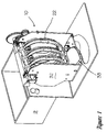
- FIGURE 1 a perspective view of the receipt storage and presenter device 10 and associated printer 9 are shown.
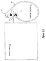
- FIGURE 2a a schematic side view of a printer mechanism 9 is illustrated.
- the printer 9 is shown discharging a receipt (arrows 8) to the storage and presenting device 10 of this invention.
- the device 10 has an overflow bucket 11, which contains two feed rollers "A” and “B”, respectively, that drive the receipt 8 into the overflow bucket 11.
- the feed rollers "A” and “B” are in pressure contact with each other, and are driven by a gear train 20 and motor 30, described in greater detail hereinbelow with respect to FIGURES 3 through 6.
- the slip or web representing the receipt 8 is discharged by printer 9 into the nip of rollers "A” and “B”, and is then wound within a rib-cage mandrel 22 disposed within the overflow bucket 11, as shown in FIGURES 1, 5a and 6. Rib-cage mandrel 22 is shown in greater detail in FIGURE 5b.
- rollers "A” and “B” have switched positions. That is, roller “B” is now disposed over roller "A”.
- Rollers “A” and “B”, respectively, are attached to, and driven by, corresponding gears “A” and “B” (FIGURES 3 and 4).
- Gears “A” and “B” are mounted for rotation about shafts 12a and 12b, respectively.
- the gears “A” and “B” are also mounted on gear plate 14 for revolution about each other, wherein gear “B”, and hence roller “B”, are driven clockwise about gear “A” and roller “A”, respectively, placing gear “B” above gear “A” for the discharge operation; and gear “B” rotates counter-clockwise to its home position to accept the next receipt.
- the purpose of this revolution is to present the receipt 8 at a greater height than that of the discharge height of printer 9.
- sensor 15 also shifts its position when gears "A” and “B” reverse positions. This is accomplished by mounting the sensor 15 upon the entrance/exit guide platform 18 (FIGURE 6), which is rotatively slaved to the rollers "A” and "B". Thus, sensor 15 can be used, first, to detect the leading edge of the receipt 8 and then to detect the trailing edge thereof.
- gear plate 14 is shown in the storage position "C", with gear “A” disposed above adjacent gear "B". In this position, the receipt 8 is caused to be fed into the overflow bucket 11.
- gear plate 14 is depicted in the presenting position "D", with gear “B” disposed above gear "A”.
- the gears "A” and “B” of gear train 20 are rotatively driven by adjacent driving gear 16, when gear train 20 is in the storage position "C".
- the driving gear 16 directly engages with gear “B” to drive rollers "A” and “B”, respectively, as shown in FIGURE 3.
- the driving gear 16 reverses direction, and also drives gear plate 14, via a slip clutch 19 and intermediate gears 23 and 24.
- the reversal of the driving gear 16 is accomplished by reversing the driving direction of motor 30.
- Reversal of the motor 30 and the engagement of the slip clutch 19 is triggered by sensor 15, which senses the leading and trailing edges of receipt 8.
- the receipt 8 is sensed by sensor 15 as it enters the overflow bucket 11.
- Sensor 15 can be a photosensor that senses the leading edge of the incoming receipt 8, and causes motor 30 to be actuated into driving the gear 16.
- the motor 30 can be made to reverse its driving direction, when the sensor 15 senses the trailing edge of the receipt web 8. Detecting the trailing edge of receipt 8 is useful for detecting a paper jam or as a signal that the receipt has been discharged to the operator.
- the sensor 15 sends a signal to reverse the motor 30 and to engage the slip clutch 19 with the intermediate gear drive (gears 23 and 24).
- Engaging the slip clutch 19 causes the gear plate 14 to rotate, thus reversing the position of the gears "A” and "B".
- a door could be actuated when the entrance guide is rotated to discharge the receipt form, ticket, etc. This door would be closed until the time of receipt discharge, in order to block the fascia entrance to the presenter, preventing foreign objects from being inserted into the presenter.
- the overflow bin area 28 of storage and presenting device 10 is shown.
- the overflow bin area 28 allows for multiple presentations.
- multiple receipt exit points can be provided, depending on the mounting orientation of the presenter in relation to the print mechanism.
- the presenter may be assembled in such a manner so as not to include means to store the receipt or web.
- the receipt if not taken by operator, could be retracted and fed in a downward direction into a bin or bucket. This would purge the presenter of any web material and allow for the next receipt.
- a trash bin area can be provided below for receipts that are rejected.
- the rollers "A” and “B”, the entrance guide 18, and the gear train 20 are all supported upon a rotatable frame 32.
- Frame 32 is pivotally supported about shaft 34.
- the shaft 34 is connected to sectional gear 33, which is driven by spur gear 35.
- the spur gear 35 is rotatively driven by a drive motor 37 via a connecting shaft 36.
- Pivoting the frame 32 allows receipt 8 to be discharged at an angle with respect to the incoming receipt direction, as shown in FIGURE 2a.
- the preferred angle is ninety degrees, but the frame 32 can be pivotally directed about any angle from zero to ninety degrees.
- a presentation field of 180 degrees is obtained.
- the sensor 15 actuates motor 37, when the trailing edge of the web is sensed.
- the presenter can be constructed in such a manner as to allow for varying widths of media. This can be done with a modular, building block approach, by which some parts and assemblies are used to build various width presenters. One presenter could also be constructed and used with two different print mechanisms, or two similar mechanisms to alternately present different media, (e.g., two color receipts from one unit and tickets or coupons from the other).
Landscapes
- Engineering & Computer Science (AREA)
- Mechanical Engineering (AREA)
- Cash Registers Or Receiving Machines (AREA)
- Pile Receivers (AREA)
Priority Applications (2)
| Application Number | Priority Date | Filing Date | Title |
|---|---|---|---|
| EP98403157A EP1010652B1 (de) | 1998-12-15 | 1998-12-15 | Vorrichtung zum Drucken, Lagern und Ausgeben von Gutscheinen |
| DE69818072T DE69818072T2 (de) | 1998-12-15 | 1998-12-15 | Vorrichtung zum Drucken, Lagern und Ausgeben von Gutscheinen |
Applications Claiming Priority (1)
| Application Number | Priority Date | Filing Date | Title |
|---|---|---|---|
| EP98403157A EP1010652B1 (de) | 1998-12-15 | 1998-12-15 | Vorrichtung zum Drucken, Lagern und Ausgeben von Gutscheinen |
Publications (2)
| Publication Number | Publication Date |
|---|---|
| EP1010652A1 true EP1010652A1 (de) | 2000-06-21 |
| EP1010652B1 EP1010652B1 (de) | 2003-09-10 |
Family
ID=8235589
Family Applications (1)
| Application Number | Title | Priority Date | Filing Date |
|---|---|---|---|
| EP98403157A Expired - Lifetime EP1010652B1 (de) | 1998-12-15 | 1998-12-15 | Vorrichtung zum Drucken, Lagern und Ausgeben von Gutscheinen |
Country Status (2)
| Country | Link |
|---|---|
| EP (1) | EP1010652B1 (de) |
| DE (1) | DE69818072T2 (de) |
Citations (5)
| Publication number | Priority date | Publication date | Assignee | Title |
|---|---|---|---|---|
| JPS602549A (ja) * | 1983-06-21 | 1985-01-08 | Toyo Tire & Rubber Co Ltd | シ−ト状物品の裏返し方法 |
| EP0409809A1 (de) * | 1989-07-20 | 1991-01-23 | DE LA RUE INTER INNOVATION Aktiebolag | Vorrichtung zur Speicherung von wertvollen Papieren |
| US5201517A (en) * | 1992-06-24 | 1993-04-13 | Xerox Corporation | Orbiting nip plural mode sheet output with faceup or facedown stacking |
| FR2751315A1 (fr) * | 1996-07-22 | 1998-01-23 | Canon Kk | Dispositif et procede de manipulation de feuille |
| US5879090A (en) * | 1997-11-07 | 1999-03-09 | Axiohm Ipb Inc. | Receipt printing, storage and discharging mechanism |
-
1998
- 1998-12-15 DE DE69818072T patent/DE69818072T2/de not_active Expired - Fee Related
- 1998-12-15 EP EP98403157A patent/EP1010652B1/de not_active Expired - Lifetime
Patent Citations (5)
| Publication number | Priority date | Publication date | Assignee | Title |
|---|---|---|---|---|
| JPS602549A (ja) * | 1983-06-21 | 1985-01-08 | Toyo Tire & Rubber Co Ltd | シ−ト状物品の裏返し方法 |
| EP0409809A1 (de) * | 1989-07-20 | 1991-01-23 | DE LA RUE INTER INNOVATION Aktiebolag | Vorrichtung zur Speicherung von wertvollen Papieren |
| US5201517A (en) * | 1992-06-24 | 1993-04-13 | Xerox Corporation | Orbiting nip plural mode sheet output with faceup or facedown stacking |
| FR2751315A1 (fr) * | 1996-07-22 | 1998-01-23 | Canon Kk | Dispositif et procede de manipulation de feuille |
| US5879090A (en) * | 1997-11-07 | 1999-03-09 | Axiohm Ipb Inc. | Receipt printing, storage and discharging mechanism |
Non-Patent Citations (1)
| Title |
|---|
| PATENT ABSTRACTS OF JAPAN vol. 009, no. 114 (M - 380) 18 May 1985 (1985-05-18) * |
Also Published As
| Publication number | Publication date |
|---|---|
| EP1010652B1 (de) | 2003-09-10 |
| DE69818072D1 (de) | 2003-10-16 |
| DE69818072T2 (de) | 2004-07-08 |
Similar Documents
| Publication | Publication Date | Title |
|---|---|---|
| US6447182B2 (en) | Duplex check printer using a print mechanism pivoted between document paths | |
| US6712253B2 (en) | Apparatus and method for dispensing tickets | |
| US20040000572A1 (en) | Ticket dispensing apparatus and method | |
| US5879090A (en) | Receipt printing, storage and discharging mechanism | |
| US5435542A (en) | Statement presenter mechanism for automated teller machine | |
| US6929416B2 (en) | Stacker for a printer | |
| US7775732B2 (en) | Multi-roll paper supply for printer | |
| US6386445B2 (en) | Medium issuing apparatus using paper roll medium and automatic teller machine using the apparatus | |
| US6966714B2 (en) | Duplex check printer having a separately driven document inverting loop | |
| EP1010652B1 (de) | Vorrichtung zum Drucken, Lagern und Ausgeben von Gutscheinen | |
| US6059160A (en) | Receipt printing and discharge mechanism | |
| US6129465A (en) | Receipt discharging mechanism | |
| US5699741A (en) | Document printer and a process for registering the documents by means of control markings using this document printer | |
| JPH11120412A (ja) | 帯供給装置およびこれを備えた紙葉類処理装置 | |
| JPH07272120A (ja) | 領収書発行装置 | |
| JP3724886B2 (ja) | 券感熱転写印刷装置 | |
| US5186104A (en) | Automatic endorser | |
| KR100288939B1 (ko) | 현금지급기의명세표및저널용지처리장치 | |
| JP2949355B2 (ja) | カード装置 | |
| JPS597095Y2 (ja) | 伝票発行装置 | |
| KR100305963B1 (ko) | 현금지급기의거래명세표용지롤자동로딩장치 | |
| JPH0565415B2 (de) | ||
| JPS63197677A (ja) | 伝票処理装置 | |
| JPH08138150A (ja) | 自動券売機の領収書発行装置 | |
| JPH0635222B2 (ja) | 通帳印字装置 |
Legal Events
| Date | Code | Title | Description |
|---|---|---|---|
| PUAI | Public reference made under article 153(3) epc to a published international application that has entered the european phase |
Free format text: ORIGINAL CODE: 0009012 |
|
| AK | Designated contracting states |
Kind code of ref document: A1 Designated state(s): DE FR GB IT SE |
|
| AX | Request for extension of the european patent |
Free format text: AL;LT;LV;MK;RO;SI |
|
| 17P | Request for examination filed |
Effective date: 20001108 |
|
| AKX | Designation fees paid |
Free format text: AT BE CH CY DE LI |
|
| RBV | Designated contracting states (corrected) |
Designated state(s): DE FR GB IT SE |
|
| 17Q | First examination report despatched |
Effective date: 20020807 |
|
| GRAH | Despatch of communication of intention to grant a patent |
Free format text: ORIGINAL CODE: EPIDOS IGRA |
|
| GRAS | Grant fee paid |
Free format text: ORIGINAL CODE: EPIDOSNIGR3 |
|
| GRAA | (expected) grant |
Free format text: ORIGINAL CODE: 0009210 |
|
| AK | Designated contracting states |
Kind code of ref document: B1 Designated state(s): DE FR GB IT SE |
|
| PG25 | Lapsed in a contracting state [announced via postgrant information from national office to epo] |
Ref country code: IT Free format text: LAPSE BECAUSE OF FAILURE TO SUBMIT A TRANSLATION OF THE DESCRIPTION OR TO PAY THE FEE WITHIN THE PRE;WARNING: LAPSES OF ITALIAN PATENTS WITH EFFECTIVE DATE BEFORE 2007 MAY HAVE OCCURRED AT ANY TIME BEFORE 2007. THE CORRECT EFFECTIVE DATE MAY BE DIFFERENT FROM THE ONE RECORDED.SCRIBED TIME-LIMIT Effective date: 20030910 Ref country code: FR Free format text: LAPSE BECAUSE OF FAILURE TO SUBMIT A TRANSLATION OF THE DESCRIPTION OR TO PAY THE FEE WITHIN THE PRESCRIBED TIME-LIMIT Effective date: 20030910 |
|
| REG | Reference to a national code |
Ref country code: GB Ref legal event code: FG4D |
|
| REF | Corresponds to: |
Ref document number: 69818072 Country of ref document: DE Date of ref document: 20031016 Kind code of ref document: P |
|
| PG25 | Lapsed in a contracting state [announced via postgrant information from national office to epo] |
Ref country code: SE Free format text: LAPSE BECAUSE OF FAILURE TO SUBMIT A TRANSLATION OF THE DESCRIPTION OR TO PAY THE FEE WITHIN THE PRESCRIBED TIME-LIMIT Effective date: 20031210 |
|
| PG25 | Lapsed in a contracting state [announced via postgrant information from national office to epo] |
Ref country code: GB Free format text: LAPSE BECAUSE OF NON-PAYMENT OF DUE FEES Effective date: 20031215 |
|
| PG25 | Lapsed in a contracting state [announced via postgrant information from national office to epo] |
Ref country code: DE Free format text: LAPSE BECAUSE OF NON-PAYMENT OF DUE FEES Effective date: 20040701 |
|
| PLBE | No opposition filed within time limit |
Free format text: ORIGINAL CODE: 0009261 |
|
| STAA | Information on the status of an ep patent application or granted ep patent |
Free format text: STATUS: NO OPPOSITION FILED WITHIN TIME LIMIT |
|
| GBPC | Gb: european patent ceased through non-payment of renewal fee |
Effective date: 20031215 |
|
| 26N | No opposition filed |
Effective date: 20040614 |
|
| EN | Fr: translation not filed |