EP1010797A1 - Maschine und Verfahren zum kontinuierlichen Dekatieren und Fixieren einer textilen Warenbahn - Google Patents
Maschine und Verfahren zum kontinuierlichen Dekatieren und Fixieren einer textilen Warenbahn Download PDFInfo
- Publication number
- EP1010797A1 EP1010797A1 EP98830768A EP98830768A EP1010797A1 EP 1010797 A1 EP1010797 A1 EP 1010797A1 EP 98830768 A EP98830768 A EP 98830768A EP 98830768 A EP98830768 A EP 98830768A EP 1010797 A1 EP1010797 A1 EP 1010797A1
- Authority
- EP
- European Patent Office
- Prior art keywords
- air
- fabric
- drum
- side wall
- blanket
- Prior art date
- Legal status (The legal status is an assumption and is not a legal conclusion. Google has not performed a legal analysis and makes no representation as to the accuracy of the status listed.)
- Granted
Links
- 239000004744 fabric Substances 0.000 title claims abstract description 73
- 230000000087 stabilizing effect Effects 0.000 title claims abstract description 18
- 238000010026 decatizing Methods 0.000 title claims abstract description 17
- 238000000034 method Methods 0.000 title claims description 6
- 230000002093 peripheral effect Effects 0.000 claims abstract description 20
- 229920006395 saturated elastomer Polymers 0.000 claims abstract description 10
- 239000004753 textile Substances 0.000 claims description 10
- 239000000463 material Substances 0.000 claims description 7
- 238000011282 treatment Methods 0.000 description 4
- 238000007664 blowing Methods 0.000 description 3
- 238000001816 cooling Methods 0.000 description 3
- 230000006641 stabilisation Effects 0.000 description 3
- 238000011105 stabilization Methods 0.000 description 3
- 229910000831 Steel Inorganic materials 0.000 description 2
- 238000012423 maintenance Methods 0.000 description 2
- 239000012466 permeate Substances 0.000 description 2
- 239000010959 steel Substances 0.000 description 2
- 210000002268 wool Anatomy 0.000 description 2
- 239000004760 aramid Substances 0.000 description 1
- 229920003235 aromatic polyamide Polymers 0.000 description 1
- 238000009833 condensation Methods 0.000 description 1
- 230000005494 condensation Effects 0.000 description 1
- 238000010276 construction Methods 0.000 description 1
- 238000001035 drying Methods 0.000 description 1
- 238000001704 evaporation Methods 0.000 description 1
- 230000008020 evaporation Effects 0.000 description 1
- 230000002349 favourable effect Effects 0.000 description 1
- 238000004519 manufacturing process Methods 0.000 description 1
- 229920000728 polyester Polymers 0.000 description 1
- 238000007790 scraping Methods 0.000 description 1
- 238000000926 separation method Methods 0.000 description 1
- 239000007787 solid Substances 0.000 description 1
Images


Classifications
-
- D—TEXTILES; PAPER
- D06—TREATMENT OF TEXTILES OR THE LIKE; LAUNDERING; FLEXIBLE MATERIALS NOT OTHERWISE PROVIDED FOR
- D06C—FINISHING, DRESSING, TENTERING OR STRETCHING TEXTILE FABRICS
- D06C7/00—Heating or cooling textile fabrics
-
- D—TEXTILES; PAPER
- D04—BRAIDING; LACE-MAKING; KNITTING; TRIMMINGS; NON-WOVEN FABRICS
- D04B—KNITTING
- D04B37/00—Auxiliary apparatus or devices for use with knitting machines
-
- D—TEXTILES; PAPER
- D06—TREATMENT OF TEXTILES OR THE LIKE; LAUNDERING; FLEXIBLE MATERIALS NOT OTHERWISE PROVIDED FOR
- D06C—FINISHING, DRESSING, TENTERING OR STRETCHING TEXTILE FABRICS
- D06C15/00—Calendering, pressing, ironing, glossing or glazing textile fabrics
- D06C15/06—Calendering, pressing, ironing, glossing or glazing textile fabrics between rollers and co-operating moving surfaces formed of flexible material, e.g. bands
-
- D—TEXTILES; PAPER
- D06—TREATMENT OF TEXTILES OR THE LIKE; LAUNDERING; FLEXIBLE MATERIALS NOT OTHERWISE PROVIDED FOR
- D06C—FINISHING, DRESSING, TENTERING OR STRETCHING TEXTILE FABRICS
- D06C2700/00—Finishing or decoration of textile materials, except for bleaching, dyeing, printing, mercerising, washing or fulling
- D06C2700/13—Steaming or decatising of fabrics or yarns
Definitions
- the present invention relates to a machine and a process for the continuous decatizing and stabilizing of a fabric.
- one finishing treatment is that known as decatizing, in which the fabric piece is treated with saturated steam at preselected pressure and temperature and then stabilized by sudden cooling.
- EP-B1-0 293 028 discloses a machine for the continuous decatizing of a fabric, comprising a cylindrical drum having a side wall covered with a textile sleeve which forms a first blanket. The fabric is partially wrapped around the sleeve and a second textile blanket is partially wrapped around the fabric. The machine also includes means capable of moving and tensioning the second blanket in order to compress the fabric against the sleeve and the side wall of the drum.
- the machine includes a sealed chamber containing saturated steam at preselected pressure and temperature for impregnating the fabric and so decatizing it. The chamber is located in a peripheral region, on the outside of and close to the drum.
- the fabric which is unwrapped from the drum is subjected to sudden cooling, in order to stabilize it, in a cylinder located above the drum.
- the cylinder has a perforated side wall around which the fabric is partially wrapped and has an inner cavity connected to an aspirator.
- the aspirator draws in air from the outside and forms a radial centripetal stream of air that passes through the fabric and through the perforated wall of the cylinder.
- the fabric thus undergoes a sudden temperature drop which serves to stabilize it.
- EP-B1-0 533 295 discloses a machine for the continuous decatizing and cooling of a fabric, comprising a rotating cylindrical drum and a fixed inner cylinder coaxial with the drum.
- the cylindrical drum has a perforated side wall covered with a sleeve of textile material which forms a first blanket.
- the fabric is partially wrapped around the sleeve and a second textile blanket is wrapped, again partially, around the fabric.
- the machine also includes means capable of moving and tensioning the second blanket in order to compress the fabric against the sleeve and the side wall of the drum.
- the fixed inner cylinder has a side wall which is radially spaced from the side wall of the drum and is provided with a perforated portion.
- One inner chamber contains saturated steam at preselected pressure and temperature which, via the perforated wall of the drum, impregnates the fabric in order to decatize it.
- Another inner chamber is located around the perforated portion of the wall of the inner cylinder and is connected to an aspirator.
- the aspirator draws in air from the outside and forms a radial centripetal stream of air that passes through the fabric and the perforated walls of the drum and of the inner cylinder. The fabric thus undergoes a sudden temperature drop which serves to stabilize it.
- the object of the present invention is to provide an improved machine and an improved method, compared with those known, for the continuous decatizing and stabilizing of a fabric.
- the invention relates to a machine for the continuous decatizing and stabilizing of a fabric, comprising
- the said second peripheral region is located immediately after the said first peripheral region with respect to the advancing direction of the said fabric.
- the said device comprises at least one opening for the air having an air port arranged on the outside of and at a preselected distance from the said side wall of the said drum.
- the said air port is arranged on the outside of the said second blanket and is substantially tangent to and in contact with it.
- the said air port is substantially rectangular and has preselected width and length, the said length being substantially equal to the length of the said drum.
- the said device comprises a plurality of openings for the air arranged side by side, having air ports arranged on the outside of and at a preselected distance from the said side wall of the said drum.
- the said air ports are arranged on the outside of the said second blanket and are substantially tangent to and in contact with it.
- the said openings for the air are connected to an air aspirator and are capable of sucking air in order to form the said stream.
- the said openings for the air are connected to an air blower and are capable of emitting jets of air in order to form the said stream.
- the said openings are connected to the said aspirator or to the said blower by respective pipes and manifolds and a respective conveying means.
- the said first blanket is a sleeve which covers the said drum.
- the said chamber is in the form of a half-cylindrical tank provided with longitudinal and semicircular seals, the said longitudinal seals being pressed by air tubes to prevent leaks between the said tank on the one hand, and the said second blanket, fabric, first blanket and side wall of the said drum on the other, while the said semicircular seals are pressed by air tubes to prevent leaks between the semicircular edges of the said tank on the one hand, and the said second blanket, fabric, first blanket and semicircular edges of the side wall of the said drum on the other.
- a half-cylindrical shell surrounds the said tank and forms an interspace containing further steam which maintains the said tank at a temperature such as to prevent condensation of the steam present in the said chamber.
- the said chamber is located substantially in two quadrants of the said drum and extends around an arc of circumference that subtends an angle of approx. 180°.
- the said openings for the air are distributed around a preselected arc of circumference substantially concentric with the said drum.
- the said openings for the air extend around an arc of circumference that subtends an angle of approx. 45°.
- the said openings for the air are positioned in a quadrant immediately following the quadrants in which the said chamber is located.
- the invention relates to a process for the continuous decatizing and stabilizing of a fabric comprising the following steps:
- the machine according to the invention has a simple and compact structure. This makes it possible to keep down the costs of construction, intallation and maintenance. It also means that the decatizing treatment can be carried out in short times, with a favourable impact on running costs.
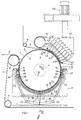
- Figs. 1-4 show a machine for the continuous decatizing and stabilizing of a fabric. It comprises a cylindrical steel drum 1.
- the drum 1 has a side wall 2 and bases 3 to each of which is fixed an axial hub 4.
- the drum 1 is supported rotatably in a frame 17 by means of the hubs 4.
- the wall 2 is made of solid steel sheet and is heated internally by steam.
- the wall 2 is covered with a sleeve 5 of textile material, which constitutes a lower blanket.
- a fabric 6 is fed by a motorized roller (not shown) and wrapped around the sleeve 5 of the drum 1 together with an upper blanket 7 of textile material.
- the fabric 6 and the blanket 7 are advanced towards the drum 1 by a motorized roller 8.
- a roller 9 guides the fabric 6, which unwraps from the cylinder 1, towards a conveyor belt (not shown) which advances the fabric 6 towards a plaiter (also not shown).
- the blanket 7 is unwrapped from the sleeve 5 of the drum 1 by a motorized roller 10 and is guided to run around a closed loop, shown only in part, by tension rollers, such as that shown with 11.
- the roller 10 has a greater angular velocity than roller 8 so that the blanket 7 is subjected to a preselected tension and compresses the fabric 6 against the sleeve 5 of the drum 1.
- the drum 1 is motorized and is rotated at the same peripheral speed as the roller 8.
- the fabric 6 and the blanket 7 are wrapped around the drum 1 through an angle of approx. 270°.
- the sleeve 5 and the blanket 7 are made of e.g. a needled felt of polyester and NomexTM (an aramid fibre of the KevlarTM family).
- the chamber 12 is formed by a half-cylindrical tank 13 having longitudinal 14 and 15 and semicircular 16 scraping seals.
- the longitudinal seals 14 and 15 are pressed by air tubes 18 and 19 to prevent leaks between the tank 13 on the one hand, and the whole of the blanket 7, fabric 6, sleeve 5 and side wall 2 of the drum 1 on the other.
- the semicircular seals 16 are pressed by air tubes 20 to prevent leaks between the semicircular edges of the tank 13 on the one hand, and the whole of the blanket 7, fabric 6, sleeve 5 and semicircular edges of the side wall 2 of the drum 1 on the other (Figs. 3 and 4).
- the half-cylindrical chamber 12 is located in the region of the two lower quadrants of the drum 1 and extends around an arc of circumference that subtends an angle of approx. 180°.
- the steam is fed into the chamber 12 via a manifold 21, two pipes 22 and 23 and sets of three pipes 24 and 25 each that feed into opposite sides of the chamber 12.
- the pipes 24 and 25 terminate in longitudinal channels 26 and 27.
- the channels 26 and 27 are provided with baffles 28 and 29 that cause separation of steam condensate and are connected to drainage pipes 30 and 31 which convey the condensate into a discharge pipe 32.
- Saturated steam is sent into the chamber 12 at an adjustable pressure, variable from atmospheric pressure with a corresponding temperature of approx. 100°C, to a maximum relative pressure of between approx. 2.8-3.0 bar with a corresponding temperature of between approx. 142-144°C.
- a half-cylindrical shell 33 surrounds the tank 13 and forms an interspace (pocket) 34 containing further steam which serves to maintain the steam present inside the chamber 12 at a temperature such as to prevent it from condensing.
- the steam is fed into the interspace 34 through a pipe 35 and sets of pipes 36 and 37 which feed into opposite sides of theinterspace.
- a discharge pipe 38 collects condensate which forms in the interspace 34.
- the half-cylindrical tank 13 and the half-cylindrical shell 33 are mounted on the frame 17.
- a suction device 40 capable of forming a stream of airfor stabilizing the fabric 6, is located in an upper peripheral region of the drum 1, on the outside of and close to the side wall 2.
- the device 40 comprises suction openings 41 connected by pipes 43, manifolds 44 and a conveying duct 45, to an air aspirator 46.
- the aspirator 46 takes the form of a fan or an air pump.
- the openings 41 have inlet ports 42 located close up to the side wall 2 of the drum 1 and practically contacting the blanket 7 (Figs. 5-7).
- Each inlet port 42 is substantially rectangular and has preselected width and length, the first being in the circumferential and the second in the longitudinal directions of the drum 1.
- the length of each inlet port 42 is substantially equal to the length of the drum 1.
- the suction device 40 is located in a peripheral region which is after the peripheral region in which the chamber 12 is located, with respect to the advancing direction of the fabric 6.
- the suction openings 41 are positioned in a quadrant immediately following the quadrants in which the chamber 12 is located and extend around an arc of circumference which subtends an angle of approx. 45°.
- the fabric 6 wrapped around the drum 1 is impregnated by the steam coming from the chamber 12.
- the portion of fabric impregnated with steam is moved underneath the suction device 40 where the openings 41, connected to the aspirator 46, suck air from the environment and form a stream of air which flows in a substantially tangential direction with respect to the side wall 2 of the drum 1.
- the stream of air permeates the fabric 6, carries away its residual moisture and causes a sudden lowering of its temperature which serves to stabilize it. In this way the fabric assumes the desired technical and aesthetic characteristics, such as dimensional stability, smooth handle and pleasing appearance.
- Fig. 8 shows a variant of the decatizing and stabilizing machine of Fig. 1 in which identical parts are shown with the same numbers.
- a blowing device 140 is associated to the drum 1.
- the blowing device 140 is capable of forming a stream of air with which to stabilize the fabric 6.
- the device 140 comprises a plurality of delivering openings 141 connected by pipes 143, manifolds 144 and a conveying duct 145, to an air blower 146.
- the blower 146 takes the form of a centripetal or reciprocating compressor.
- the openings 141 have air outlet ports 142 located close up to the side wall 2 of the drum 1 and practically contacting the blanket 7 (Fig. 8).
- the blowing device 140 performs a similar function to the suction device 40.
- the openings 141 are able to emit jets of air which form a stream flowing in a substantially tangential direction with respect to the side wall 2 of the drum 1.
- the stream of air permeates the fabric 6, carries away its residual moisture and causes a sudden lowering of its temperature which serves to stabilize it.
Landscapes
- Engineering & Computer Science (AREA)
- Textile Engineering (AREA)
- Treatment Of Fiber Materials (AREA)
- Preliminary Treatment Of Fibers (AREA)
Priority Applications (6)
| Application Number | Priority Date | Filing Date | Title |
|---|---|---|---|
| EP98830768A EP1010797B1 (de) | 1998-12-18 | 1998-12-18 | Maschine und Verfahren zum kontinuierlichen Dekatieren und Fixieren einer textilen Warenbahn |
| ES98830768T ES2193504T3 (es) | 1998-12-18 | 1998-12-18 | Maquina y procedimiento para decatizar y estabilizar tejido de forma continua. |
| DE69812384T DE69812384T2 (de) | 1998-12-18 | 1998-12-18 | Maschine und Verfahren zum kontinuierlichen Dekatieren und Fixieren einer textilen Warenbahn |
| AT98830768T ATE234955T1 (de) | 1998-12-18 | 1998-12-18 | Maschine und verfahren zum kontinuierlichen dekatieren und fixieren einer textilen warenbahn |
| TR1999/02952A TR199902952A2 (xx) | 1998-12-18 | 1999-12-03 | Bir kuma��n s�rekli olarak kolas�n� gidermek ve dengelemek i�in makine ve y�ntem. |
| KR1019990056062A KR100672286B1 (ko) | 1998-12-18 | 1999-12-09 | 연속적으로 편물을 디케타이징하고 안정화시키는 기계 및공정 |
Applications Claiming Priority (1)
| Application Number | Priority Date | Filing Date | Title |
|---|---|---|---|
| EP98830768A EP1010797B1 (de) | 1998-12-18 | 1998-12-18 | Maschine und Verfahren zum kontinuierlichen Dekatieren und Fixieren einer textilen Warenbahn |
Publications (2)
| Publication Number | Publication Date |
|---|---|
| EP1010797A1 true EP1010797A1 (de) | 2000-06-21 |
| EP1010797B1 EP1010797B1 (de) | 2003-03-19 |
Family
ID=8236920
Family Applications (1)
| Application Number | Title | Priority Date | Filing Date |
|---|---|---|---|
| EP98830768A Expired - Lifetime EP1010797B1 (de) | 1998-12-18 | 1998-12-18 | Maschine und Verfahren zum kontinuierlichen Dekatieren und Fixieren einer textilen Warenbahn |
Country Status (6)
| Country | Link |
|---|---|
| EP (1) | EP1010797B1 (de) |
| KR (1) | KR100672286B1 (de) |
| AT (1) | ATE234955T1 (de) |
| DE (1) | DE69812384T2 (de) |
| ES (1) | ES2193504T3 (de) |
| TR (1) | TR199902952A2 (de) |
Cited By (2)
| Publication number | Priority date | Publication date | Assignee | Title |
|---|---|---|---|---|
| ITVI20130121A1 (it) * | 2013-04-29 | 2013-07-29 | Red Carpet S R L | Procedimento per il trattamento di decatissaggio e stabilizzazione in continuo di un materiale tessile |
| WO2015144623A1 (en) | 2014-03-25 | 2015-10-01 | Red Carpet S.R.L. | Machine for the continuous decatising treatment of textile material |
Families Citing this family (1)
| Publication number | Priority date | Publication date | Assignee | Title |
|---|---|---|---|---|
| CN106937046B (zh) * | 2017-03-07 | 2023-07-25 | 广东创达自动化装备有限公司 | 圆纬机布面实时图像的获取装置及方法 |
Citations (2)
| Publication number | Priority date | Publication date | Assignee | Title |
|---|---|---|---|---|
| EP0293028A2 (de) * | 1987-05-26 | 1988-11-30 | SPEROTTO RIMAR S.p.A. | Verfahren und Vorrichtung zum kontinuierlichen Dekatieren von Geweben |
| EP0533295A1 (de) * | 1991-09-19 | 1993-03-24 | SPEROTTO RIMAR S.p.A. | Vorrichtung und Verfahren zum kontinuierlichen Dekatieren von Geweben |
-
1998
- 1998-12-18 EP EP98830768A patent/EP1010797B1/de not_active Expired - Lifetime
- 1998-12-18 ES ES98830768T patent/ES2193504T3/es not_active Expired - Lifetime
- 1998-12-18 DE DE69812384T patent/DE69812384T2/de not_active Expired - Lifetime
- 1998-12-18 AT AT98830768T patent/ATE234955T1/de not_active IP Right Cessation
-
1999
- 1999-12-03 TR TR1999/02952A patent/TR199902952A2/xx unknown
- 1999-12-09 KR KR1019990056062A patent/KR100672286B1/ko not_active Expired - Lifetime
Patent Citations (2)
| Publication number | Priority date | Publication date | Assignee | Title |
|---|---|---|---|---|
| EP0293028A2 (de) * | 1987-05-26 | 1988-11-30 | SPEROTTO RIMAR S.p.A. | Verfahren und Vorrichtung zum kontinuierlichen Dekatieren von Geweben |
| EP0533295A1 (de) * | 1991-09-19 | 1993-03-24 | SPEROTTO RIMAR S.p.A. | Vorrichtung und Verfahren zum kontinuierlichen Dekatieren von Geweben |
Cited By (2)
| Publication number | Priority date | Publication date | Assignee | Title |
|---|---|---|---|---|
| ITVI20130121A1 (it) * | 2013-04-29 | 2013-07-29 | Red Carpet S R L | Procedimento per il trattamento di decatissaggio e stabilizzazione in continuo di un materiale tessile |
| WO2015144623A1 (en) | 2014-03-25 | 2015-10-01 | Red Carpet S.R.L. | Machine for the continuous decatising treatment of textile material |
Also Published As
| Publication number | Publication date |
|---|---|
| DE69812384D1 (de) | 2003-04-24 |
| ATE234955T1 (de) | 2003-04-15 |
| TR199902952A3 (tr) | 2000-07-21 |
| ES2193504T3 (es) | 2003-11-01 |
| EP1010797B1 (de) | 2003-03-19 |
| TR199902952A2 (xx) | 2000-07-21 |
| KR100672286B1 (ko) | 2007-01-22 |
| DE69812384T2 (de) | 2003-12-18 |
| KR20000048025A (ko) | 2000-07-25 |
Similar Documents
| Publication | Publication Date | Title |
|---|---|---|
| CA2090783C (en) | Method and device for drying paper | |
| US3089252A (en) | Web moisture profile control for paper machine | |
| JP2655801B2 (ja) | ソフトティッシュ抄紙機のヤンキープレスの性能向上方法および装置 | |
| US3098371A (en) | Perforated drum material treatment device having a plurality of treatment zones | |
| US4328626A (en) | Apparatus for drying a fibrous web | |
| US4297794A (en) | Paper sheet dryer | |
| CN1409786A (zh) | 用于穿透空气干燥式造纸机的密封装置 | |
| EP1010797B1 (de) | Maschine und Verfahren zum kontinuierlichen Dekatieren und Fixieren einer textilen Warenbahn | |
| US3384973A (en) | Ventilating dryers | |
| JP2004113790A (ja) | 乾燥機 | |
| EP1592842A2 (de) | Hochdruckumlufttrockner und dessen betrieb | |
| JPH05195416A (ja) | 連続布のデカタイジング装置及び関連の方法 | |
| US4599814A (en) | Method and equipment for mangling wet laundry | |
| CA1316668C (en) | Pocket ventilator | |
| CA2264376C (en) | Continuous drying apparatus for porous web | |
| JP4012944B2 (ja) | ロールアイロナ | |
| US3686903A (en) | Apparatus for the contact-free treatment of materials which can be stressed in a lengthwise direction | |
| CN111778660A (zh) | 一种低带液量轧车 | |
| US5522151A (en) | Single tier dryer section with dual reversing rolls | |
| KR100283024B1 (ko) | 다공질 웨브의 연속건조장치 | |
| JPH03174084A (ja) | 紙の乾燥を強化する方法および装置 | |
| KR100510396B1 (ko) | 섬유 웹 건조 방법 및 건조 장치 | |
| US3992746A (en) | Apparatus for the treatment of textile fabrics | |
| US3387384A (en) | Paper drying machinery | |
| CN215113741U (zh) | 一种防止布料脱离烘筒的低张力烘燥装置 |
Legal Events
| Date | Code | Title | Description |
|---|---|---|---|
| PUAI | Public reference made under article 153(3) epc to a published international application that has entered the european phase |
Free format text: ORIGINAL CODE: 0009012 |
|
| AK | Designated contracting states |
Kind code of ref document: A1 Designated state(s): AT CH DE ES FR GB IT LI PT |
|
| AX | Request for extension of the european patent |
Free format text: AL;LT;LV;MK;RO;SI |
|
| 17P | Request for examination filed |
Effective date: 20000826 |
|
| AKX | Designation fees paid |
Free format text: AT BE CH CY DE DK ES FI LI |
|
| RBV | Designated contracting states (corrected) |
Designated state(s): AT CH DE ES FR GB IT LI PT |
|
| RAP1 | Party data changed (applicant data changed or rights of an application transferred) |
Owner name: SPEROTTO RIMAR S.R.L. |
|
| RAP1 | Party data changed (applicant data changed or rights of an application transferred) |
Owner name: SPEROTTO RIMAR S.P.A. |
|
| RAP1 | Party data changed (applicant data changed or rights of an application transferred) |
Owner name: SPEROTTO RIMAR S.R.L. |
|
| GRAH | Despatch of communication of intention to grant a patent |
Free format text: ORIGINAL CODE: EPIDOS IGRA |
|
| GRAH | Despatch of communication of intention to grant a patent |
Free format text: ORIGINAL CODE: EPIDOS IGRA |
|
| GRAA | (expected) grant |
Free format text: ORIGINAL CODE: 0009210 |
|
| AK | Designated contracting states |
Designated state(s): AT CH DE ES FR GB IT LI PT |
|
| PG25 | Lapsed in a contracting state [announced via postgrant information from national office to epo] |
Ref country code: AT Free format text: LAPSE BECAUSE OF FAILURE TO SUBMIT A TRANSLATION OF THE DESCRIPTION OR TO PAY THE FEE WITHIN THE PRESCRIBED TIME-LIMIT Effective date: 20030319 |
|
| REG | Reference to a national code |
Ref country code: GB Ref legal event code: FG4D |
|
| REG | Reference to a national code |
Ref country code: CH Ref legal event code: EP |
|
| REF | Corresponds to: |
Ref document number: 69812384 Country of ref document: DE Date of ref document: 20030424 Kind code of ref document: P |
|
| PG25 | Lapsed in a contracting state [announced via postgrant information from national office to epo] |
Ref country code: PT Free format text: LAPSE BECAUSE OF FAILURE TO SUBMIT A TRANSLATION OF THE DESCRIPTION OR TO PAY THE FEE WITHIN THE PRESCRIBED TIME-LIMIT Effective date: 20030620 |
|
| REG | Reference to a national code |
Ref country code: CH Ref legal event code: NV Representative=s name: E. BLUM & CO. PATENTANWAELTE |
|
| ET | Fr: translation filed | ||
| REG | Reference to a national code |
Ref country code: ES Ref legal event code: FG2A Ref document number: 2193504 Country of ref document: ES Kind code of ref document: T3 |
|
| PLBE | No opposition filed within time limit |
Free format text: ORIGINAL CODE: 0009261 |
|
| STAA | Information on the status of an ep patent application or granted ep patent |
Free format text: STATUS: NO OPPOSITION FILED WITHIN TIME LIMIT |
|
| 26N | No opposition filed |
Effective date: 20031222 |
|
| PGFP | Annual fee paid to national office [announced via postgrant information from national office to epo] |
Ref country code: FR Payment date: 20050831 Year of fee payment: 8 |
|
| PGFP | Annual fee paid to national office [announced via postgrant information from national office to epo] |
Ref country code: ES Payment date: 20051207 Year of fee payment: 8 |
|
| REG | Reference to a national code |
Ref country code: FR Ref legal event code: ST Effective date: 20070831 |
|
| REG | Reference to a national code |
Ref country code: CH Ref legal event code: PFA Owner name: SPEROTTO RIMAR S.R.L. Free format text: SPEROTTO RIMAR S.R.L.#VIA MARCORA, 7#20121 MILANO (IT) -TRANSFER TO- SPEROTTO RIMAR S.R.L.#VIA MARCORA, 7#20121 MILANO (IT) |
|
| PGFP | Annual fee paid to national office [announced via postgrant information from national office to epo] |
Ref country code: CH Payment date: 20071127 Year of fee payment: 10 |
|
| REG | Reference to a national code |
Ref country code: ES Ref legal event code: FD2A Effective date: 20061219 |
|
| PG25 | Lapsed in a contracting state [announced via postgrant information from national office to epo] |
Ref country code: FR Free format text: LAPSE BECAUSE OF NON-PAYMENT OF DUE FEES Effective date: 20070102 Ref country code: ES Free format text: LAPSE BECAUSE OF NON-PAYMENT OF DUE FEES Effective date: 20061219 |
|
| PGFP | Annual fee paid to national office [announced via postgrant information from national office to epo] |
Ref country code: GB Payment date: 20071129 Year of fee payment: 10 |
|
| REG | Reference to a national code |
Ref country code: CH Ref legal event code: PL |
|
| GBPC | Gb: european patent ceased through non-payment of renewal fee |
Effective date: 20081218 |
|
| PG25 | Lapsed in a contracting state [announced via postgrant information from national office to epo] |
Ref country code: LI Free format text: LAPSE BECAUSE OF NON-PAYMENT OF DUE FEES Effective date: 20081231 Ref country code: CH Free format text: LAPSE BECAUSE OF NON-PAYMENT OF DUE FEES Effective date: 20081231 |
|
| PG25 | Lapsed in a contracting state [announced via postgrant information from national office to epo] |
Ref country code: GB Free format text: LAPSE BECAUSE OF NON-PAYMENT OF DUE FEES Effective date: 20081218 |
|
| PGFP | Annual fee paid to national office [announced via postgrant information from national office to epo] |
Ref country code: DE Payment date: 20171120 Year of fee payment: 20 |
|
| PGFP | Annual fee paid to national office [announced via postgrant information from national office to epo] |
Ref country code: IT Payment date: 20171120 Year of fee payment: 20 |
|
| REG | Reference to a national code |
Ref country code: DE Ref legal event code: R071 Ref document number: 69812384 Country of ref document: DE |