EP1010833A2 - Procédé et dispositif pour le montage de panneaux de plancher surélevé - Google Patents
Procédé et dispositif pour le montage de panneaux de plancher surélevé Download PDFInfo
- Publication number
- EP1010833A2 EP1010833A2 EP99125211A EP99125211A EP1010833A2 EP 1010833 A2 EP1010833 A2 EP 1010833A2 EP 99125211 A EP99125211 A EP 99125211A EP 99125211 A EP99125211 A EP 99125211A EP 1010833 A2 EP1010833 A2 EP 1010833A2
- Authority
- EP
- European Patent Office
- Prior art keywords
- support
- der
- plate
- floor
- floor plate
- Prior art date
- Legal status (The legal status is an assumption and is not a legal conclusion. Google has not performed a legal analysis and makes no representation as to the accuracy of the status listed.)
- Withdrawn
Links
Images

Classifications
-
- E—FIXED CONSTRUCTIONS
- E04—BUILDING
- E04F—FINISHING WORK ON BUILDINGS, e.g. STAIRS, FLOORS
- E04F15/00—Flooring
- E04F15/02—Flooring or floor layers composed of a number of similar elements
- E04F15/024—Sectional false floors, e.g. computer floors
-
- E—FIXED CONSTRUCTIONS
- E04—BUILDING
- E04F—FINISHING WORK ON BUILDINGS, e.g. STAIRS, FLOORS
- E04F15/00—Flooring
- E04F15/02—Flooring or floor layers composed of a number of similar elements
- E04F15/024—Sectional false floors, e.g. computer floors
- E04F15/02447—Supporting structures
- E04F15/02464—Height adjustable elements for supporting the panels or a panel-supporting framework
- E04F15/0247—Screw jacks
- E04F15/02476—Screw jacks height-adjustable from the upper side of the floor
Definitions
- the invention relates to a method and one used for the method Device for mounting raised floor panels after the Preamble of process claim 1.
- a method has become known from DE 1 196 345 in which Floor slabs on a row of rows and columns on one Footprints arranged in a distributed manner.
- each support plate each support placed a corner of a floor plate, so that the support plate thus carries several corners of floor panels.
- the middle Area (outside the edge areas) then carries one support plate each Support a total of four corners from four different floor panels.
- Such a method for laying floor slabs on such Support has proven itself.
- the disadvantage is the considerable amount of work, which is connected to the alignment of the support plates on the supports.
- the Supports are not designed to be height adjustable, but can only Unevenness of the contact surface can be compensated for by the fact that Support plates corresponding additional compensation plates placed or appropriate compensation support plates are removed, which approximately the Floor panels can be aligned horizontally. after the additional support plates to be placed or removed have a finite thickness have, this means that the height compensation on the support plate overlying floor panels cannot be done very precisely because it can Always remove or add a compensation plate as the smallest unit become.
- the invention is therefore based on DE 1 196 345 the task based on a method of the type mentioned in such a way that it can be done much faster that it is more accurate Compensation of the floor panels comes and that in addition with such Procedure, the sound insulation values can be significantly improved.
- An essential feature of the invention is that now at least one Floor plate with its corner glued to the support plate of the to be aligned Bracket is attached and that to align this floor plate with the the support adhering to the underside is now simply arranged in the support Spindle is actuated, which can be actuated through the support plate, so that while observing the floor slab to be aligned the spirit level lying in the support from above through the Support plate can be operated until the floor plate to be aligned is aligned horizontally.
- the support does not necessarily need to be lifted from the surface by hand become. It was said at the beginning that the support on the underside of the Adheres to the floor plate (e.g. using double-sided adhesive tape) and that you just temporarily lift the floor panel so far by hand, until the spirit level indicates that the floor slab is level located. If you fix this raised position with your hand, you can use the tool to simultaneously operate the spindle in the support, the Actuation continues until the support leg of the support is on the installation surface sits on.
- the support is thus relieved set, while in the second embodiment, the support under load is set.
- the access hole is therefore preferably at the intersection of all four edges of the floor slabs placed on the support plate, because it is on is most easily accessible.
- a support for the practice of the method is characterized in that the Support consists of a support plate which is connected to a support tube in which a spindle nut and an associated spindle are arranged.
- Figure 1 shows that initially a series of supports 3 provisionally on one Support level 4 can be designed and one or more floor slabs 1,2 the supports are put on.
- the floor slabs are placed in the With regard to the supports 3 so that the corners of the respective floor slab 1,2 about 1 ⁇ 4 covers the support plate 5 of the supports 3 arranged on the corner, so as shown in Figure 1.
- An alignment tool such as a spirit level or the like, placed on the floor plate 1 and at the same time with the hand Floor plate 1 in Figure 2 raised at the corner so that the support 3 with their support leg 9 stands out from the support level 4.
- the lifting takes place provisionally so that the level placed on the floor plate 1 aligned state.
- a tool Access hole 6 retracted and the spindle 14 ( Figure 3) actuated in that the Tool (e.g. an Allen key) is inserted into the actuation holder 15 and the spindle 14 rotates.
- the spindle 14 is now rotated with the tool so far that the damping foot 17 fits snugly on the support level 4, whereby the Floor plate 1 is now aligned at this corner.
- the floor panels 1, 2 are made of tongue and groove boards exist because it then also forms a positive connection the abutting floor panels 1, 2 comes.
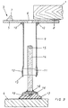
- the support 3 consists essentially of the upper support plate 5, the is connected to a support tube 9, for example via a welding point 10. At the lower, free end of the support tube is a spindle nut 11 in the tube pressed in, so that the compression 12, the spindle nut 11 form-fitting surrounds.
- a lower, flanged edge 13 ensures that the spindle nut 11 is not can be pulled down out of the support tube 9. It is about in other words a very simple and inexpensive connection because there is no need for welded or adhesive connections.
- the invention is not limited to this; in another Embodiment can be provided that the spindle nut 11 by means of a Spot welding is attached to the inside of the support tube 9.
- the spindle nut 11 is penetrated by the spindle 14, which on its upper, free end of an actuating receptacle 15 for engaging, for example, a Allen key has.
- the Allen key is here by the Access opening 6 in the support plate 5 retracted into the support tube 9 and into the Actuating receptacle 15 inserted.
- a semicircular support plate 16 is welded to the underside of the spindle 14, which has a downward cam 18 in its center, which extends into one elastic material trained damping foot 17 engages.
- the support 3 By arranging elastic adhesive dots 7 on the support plate 5 and by the arrangement of the lower damping foot 17, the support 3 forms a effective interruption of a structure-borne noise line, so that the raised Floor slabs have an excellent structure-borne sound insulation.
Landscapes
- Engineering & Computer Science (AREA)
- Architecture (AREA)
- General Engineering & Computer Science (AREA)
- Civil Engineering (AREA)
- Structural Engineering (AREA)
- Floor Finish (AREA)
- Building Environments (AREA)
Applications Claiming Priority (2)
| Application Number | Priority Date | Filing Date | Title |
|---|---|---|---|
| DE19858693 | 1998-12-18 | ||
| DE1998158693 DE19858693A1 (de) | 1998-12-18 | 1998-12-18 | Verfahren und Vorrichtung zur Montage von aufgeständerten Fußbodenplatten |
Publications (2)
| Publication Number | Publication Date |
|---|---|
| EP1010833A2 true EP1010833A2 (fr) | 2000-06-21 |
| EP1010833A3 EP1010833A3 (fr) | 2000-10-11 |
Family
ID=7891717
Family Applications (1)
| Application Number | Title | Priority Date | Filing Date |
|---|---|---|---|
| EP99125211A Withdrawn EP1010833A3 (fr) | 1998-12-18 | 1999-12-17 | Procédé et dispositif pour le montage de panneaux de plancher surélevé |
Country Status (2)
| Country | Link |
|---|---|
| EP (1) | EP1010833A3 (fr) |
| DE (1) | DE19858693A1 (fr) |
Cited By (5)
| Publication number | Priority date | Publication date | Assignee | Title |
|---|---|---|---|---|
| DE20107927U1 (de) | 2001-05-11 | 2001-09-13 | DWA Deutsche Waggonbau GmbH, 12526 Berlin | Fußboden für Transportmittel, insbesondere für Schienenfahrzeuge |
| EP1256501A3 (fr) * | 2001-05-11 | 2003-11-05 | DWA Deutsche Waggonbau GmbH | Procédé pour poser un plancher en moyens de transport, en particulier en véhicules ferroviaires, et plancher pour moyens de transport |
| EP1568829A3 (fr) * | 2004-02-26 | 2008-05-21 | Getzner Werkstoffe Holding GmbH | Pied pour le support élastique des panneaux de planchers |
| EP2951071B1 (fr) | 2013-01-29 | 2017-03-08 | Siemens Aktiengesellschaft | Véhicule ferroviaire |
| WO2020152520A1 (fr) | 2019-01-24 | 2020-07-30 | Solidor Bvba | Socle de terrasse amélioré |
Family Cites Families (5)
| Publication number | Priority date | Publication date | Assignee | Title |
|---|---|---|---|---|
| GB8714214D0 (en) * | 1987-06-17 | 1987-07-22 | Jack Flooring Co Ltd | Floor panel support system |
| CH675003A5 (en) * | 1988-02-19 | 1990-08-15 | Guenter Feurstein | Support for panels of hollow floor - has means to adjust height of panels above underfloor |
| DE4228601C2 (de) * | 1991-09-11 | 1997-06-19 | Taisei Electronic Ind Co | Verfahren zum Aufbau eines erhöhten Trockenbodens und die zugehörige Trockenfußbodeneinheit |
| JPH08260678A (ja) * | 1995-03-22 | 1996-10-08 | Taisei Denki Kogyo:Kk | 床パネル及びそれを用いた乾式置床工法 |
| DE19631880C2 (de) * | 1996-08-07 | 1998-07-02 | Sicowa Verfahrenstech | Hohlraumbodenstütze |
-
1998
- 1998-12-18 DE DE1998158693 patent/DE19858693A1/de not_active Withdrawn
-
1999
- 1999-12-17 EP EP99125211A patent/EP1010833A3/fr not_active Withdrawn
Cited By (9)
| Publication number | Priority date | Publication date | Assignee | Title |
|---|---|---|---|---|
| DE20107927U1 (de) | 2001-05-11 | 2001-09-13 | DWA Deutsche Waggonbau GmbH, 12526 Berlin | Fußboden für Transportmittel, insbesondere für Schienenfahrzeuge |
| EP1256501A3 (fr) * | 2001-05-11 | 2003-11-05 | DWA Deutsche Waggonbau GmbH | Procédé pour poser un plancher en moyens de transport, en particulier en véhicules ferroviaires, et plancher pour moyens de transport |
| EP1568829A3 (fr) * | 2004-02-26 | 2008-05-21 | Getzner Werkstoffe Holding GmbH | Pied pour le support élastique des panneaux de planchers |
| EP2951071B1 (fr) | 2013-01-29 | 2017-03-08 | Siemens Aktiengesellschaft | Véhicule ferroviaire |
| EP2951071B2 (fr) † | 2013-01-29 | 2020-02-12 | Siemens Mobility GmbH | Véhicule ferroviaire |
| WO2020152520A1 (fr) | 2019-01-24 | 2020-07-30 | Solidor Bvba | Socle de terrasse amélioré |
| BE1026990A1 (nl) | 2019-01-24 | 2020-08-17 | Solidor Bvba | Verbeterde terrasdrager |
| BE1026989B1 (nl) * | 2019-01-24 | 2020-08-25 | Solidor Bvba | Verbeterde terrasdrager |
| BE1026990B1 (nl) * | 2019-01-24 | 2020-08-25 | Solidor Bvba | Verbeterde terrasdrager |
Also Published As
| Publication number | Publication date |
|---|---|
| EP1010833A3 (fr) | 2000-10-11 |
| DE19858693A1 (de) | 2000-06-21 |
Similar Documents
| Publication | Publication Date | Title |
|---|---|---|
| EP0362718B1 (fr) | Barre de trame pour planchers surélevés | |
| EP0562417A2 (fr) | Etagère pour stocker des pièces à usiner plates | |
| DE69418712T2 (de) | Abstützvorrichtung | |
| DE2927116C2 (fr) | ||
| EP1010833A2 (fr) | Procédé et dispositif pour le montage de panneaux de plancher surélevé | |
| EP1211215B1 (fr) | Transstockeur et procédé pour la réalisation d' une connection à plaques dans un transstockeur | |
| DE69316906T2 (de) | Treppen-Lehre | |
| EP3922784B1 (fr) | Dispositif de nivellement et lissage de chapes | |
| DE1941329A1 (de) | Vorrichtung zur Herstellung eines vorgebogenen Traegers | |
| DE1040356B (de) | Warengestell mit in ihrer Hoehenlage verstellbaren Auflageboeden | |
| DE69612704T2 (de) | Verfahren zur Bedeckung eines Schiffsdecks, vorgefertigte Bedeckungseinheit und Verfahren zu ihrer Herstellung | |
| DE2626601B2 (de) | Verfahren zum Ersetzen der senkrechten Pfosten von Portalsparren durch eine pfostenfreie Unterstützung und Dreigelenkrahmen zur Durchführung des Verfahrens | |
| DE69304089T2 (de) | Selbstverriegelndes Klemmelement und dazugehörende Befestigungsvorrichtung für dieses Klemmelement | |
| EP0674065A1 (fr) | Dispositif pour mettre en place et pour niveler les supports de planchers à doubles fonds surélevés | |
| DE1402897A1 (de) | Bohrgeraete fuer Walzprofilstuecke | |
| DE19718061C1 (de) | Installationsbodenstütze | |
| DE8913789U1 (de) | Installationsboden | |
| EP1308117A1 (fr) | Dispositif de support de baignoire et méthode et ensemble pour monter une baignoire dans un support de baignoire | |
| DE2833450A1 (de) | Anordnung zur lagekorrektur eines bauwerkes | |
| DE1816624C (de) | Freitragender Treppenlauf | |
| DE8030988U1 (de) | Fliesenschneidgeraet | |
| DE3447645C2 (fr) | ||
| DE202006007863U1 (de) | Fundament-Ausbildung für Hebebühnen | |
| DE2125260C3 (de) | Lagerplatte aus elastischem Werkstoff als Unterstützung und Abstandshalterung von Treppenstufen o.dgl | |
| DE4324898C2 (de) | Tischförmiges Möbel mit einer Arbeits-, Ablage- oder Tischplatte, insbesondere Arbeits- oder Bürotisch |
Legal Events
| Date | Code | Title | Description |
|---|---|---|---|
| PUAI | Public reference made under article 153(3) epc to a published international application that has entered the european phase |
Free format text: ORIGINAL CODE: 0009012 |
|
| AK | Designated contracting states |
Kind code of ref document: A2 Designated state(s): AT BE CH CY DE DK ES FI FR GB GR IE IT LI LU MC NL PT SE |
|
| AX | Request for extension of the european patent |
Free format text: AL;LT;LV;MK;RO;SI |
|
| PUAL | Search report despatched |
Free format text: ORIGINAL CODE: 0009013 |
|
| AK | Designated contracting states |
Kind code of ref document: A3 Designated state(s): AT BE CH CY DE DK ES FI FR GB GR IE IT LI LU MC NL PT SE |
|
| AX | Request for extension of the european patent |
Free format text: AL;LT;LV;MK;RO;SI |
|
| AKX | Designation fees paid | ||
| STAA | Information on the status of an ep patent application or granted ep patent |
Free format text: STATUS: THE APPLICATION IS DEEMED TO BE WITHDRAWN |
|
| 18D | Application deemed to be withdrawn |
Effective date: 20010412 |
|
| REG | Reference to a national code |
Ref country code: DE Ref legal event code: 8566 |