EP1010878A2 - Dispositif de positionement à raideur variable pour la fixation d'un boítier d'engrenage - Google Patents
Dispositif de positionement à raideur variable pour la fixation d'un boítier d'engrenage Download PDFInfo
- Publication number
- EP1010878A2 EP1010878A2 EP99309882A EP99309882A EP1010878A2 EP 1010878 A2 EP1010878 A2 EP 1010878A2 EP 99309882 A EP99309882 A EP 99309882A EP 99309882 A EP99309882 A EP 99309882A EP 1010878 A2 EP1010878 A2 EP 1010878A2
- Authority
- EP
- European Patent Office
- Prior art keywords
- gearbox
- link
- engine
- engine case
- chamber
- Prior art date
- Legal status (The legal status is an assumption and is not a legal conclusion. Google has not performed a legal analysis and makes no representation as to the accuracy of the status listed.)
- Granted
Links
- 238000002955 isolation Methods 0.000 claims abstract description 15
- 230000007246 mechanism Effects 0.000 claims abstract description 11
- 229920001971 elastomer Polymers 0.000 claims abstract description 9
- 239000000806 elastomer Substances 0.000 claims abstract description 9
- 239000012530 fluid Substances 0.000 claims description 24
- 230000005540 biological transmission Effects 0.000 claims description 5
- 230000002829 reductive effect Effects 0.000 claims description 3
- 230000004044 response Effects 0.000 claims description 3
- 230000008878 coupling Effects 0.000 claims 3
- 238000010168 coupling process Methods 0.000 claims 3
- 238000005859 coupling reaction Methods 0.000 claims 3
- 230000007423 decrease Effects 0.000 claims 2
- 230000008901 benefit Effects 0.000 description 6
- 238000013016 damping Methods 0.000 description 6
- 239000000463 material Substances 0.000 description 6
- 230000036961 partial effect Effects 0.000 description 5
- 230000006835 compression Effects 0.000 description 4
- 238000007906 compression Methods 0.000 description 4
- 238000004519 manufacturing process Methods 0.000 description 4
- 239000000446 fuel Substances 0.000 description 3
- 230000002411 adverse Effects 0.000 description 2
- 230000005611 electricity Effects 0.000 description 2
- 238000010008 shearing Methods 0.000 description 2
- XAGFODPZIPBFFR-UHFFFAOYSA-N aluminium Chemical compound [Al] XAGFODPZIPBFFR-UHFFFAOYSA-N 0.000 description 1
- 229910052782 aluminium Inorganic materials 0.000 description 1
- 230000009286 beneficial effect Effects 0.000 description 1
- 238000002485 combustion reaction Methods 0.000 description 1
- 230000001010 compromised effect Effects 0.000 description 1
- 238000010276 construction Methods 0.000 description 1
- 238000001816 cooling Methods 0.000 description 1
- 238000006073 displacement reaction Methods 0.000 description 1
- 230000000694 effects Effects 0.000 description 1
- 238000005516 engineering process Methods 0.000 description 1
- 239000004744 fabric Substances 0.000 description 1
- 238000010438 heat treatment Methods 0.000 description 1
- 230000000670 limiting effect Effects 0.000 description 1
- 238000005461 lubrication Methods 0.000 description 1
- 230000000452 restraining effect Effects 0.000 description 1
- 238000005728 strengthening Methods 0.000 description 1
- 230000007704 transition Effects 0.000 description 1
Images


Classifications
-
- F—MECHANICAL ENGINEERING; LIGHTING; HEATING; WEAPONS; BLASTING
- F02—COMBUSTION ENGINES; HOT-GAS OR COMBUSTION-PRODUCT ENGINE PLANTS
- F02C—GAS-TURBINE PLANTS; AIR INTAKES FOR JET-PROPULSION PLANTS; CONTROLLING FUEL SUPPLY IN AIR-BREATHING JET-PROPULSION PLANTS
- F02C7/00—Features, components parts, details or accessories, not provided for in, or of interest apart form groups F02C1/00 - F02C6/00; Air intakes for jet-propulsion plants
- F02C7/32—Arrangement, mounting, or driving, of auxiliaries
-
- F—MECHANICAL ENGINEERING; LIGHTING; HEATING; WEAPONS; BLASTING
- F16—ENGINEERING ELEMENTS AND UNITS; GENERAL MEASURES FOR PRODUCING AND MAINTAINING EFFECTIVE FUNCTIONING OF MACHINES OR INSTALLATIONS; THERMAL INSULATION IN GENERAL
- F16F—SPRINGS; SHOCK-ABSORBERS; MEANS FOR DAMPING VIBRATION
- F16F1/00—Springs
- F16F1/36—Springs made of rubber or other material having high internal friction, e.g. thermoplastic elastomers
- F16F1/42—Springs made of rubber or other material having high internal friction, e.g. thermoplastic elastomers characterised by the mode of stressing
- F16F1/44—Springs made of rubber or other material having high internal friction, e.g. thermoplastic elastomers characterised by the mode of stressing loaded mainly in compression
- F16F1/445—Springs made of rubber or other material having high internal friction, e.g. thermoplastic elastomers characterised by the mode of stressing loaded mainly in compression the spring material being contained in a generally closed space
-
- F—MECHANICAL ENGINEERING; LIGHTING; HEATING; WEAPONS; BLASTING
- F16—ENGINEERING ELEMENTS AND UNITS; GENERAL MEASURES FOR PRODUCING AND MAINTAINING EFFECTIVE FUNCTIONING OF MACHINES OR INSTALLATIONS; THERMAL INSULATION IN GENERAL
- F16F—SPRINGS; SHOCK-ABSORBERS; MEANS FOR DAMPING VIBRATION
- F16F7/00—Vibration-dampers; Shock-absorbers
-
- F—MECHANICAL ENGINEERING; LIGHTING; HEATING; WEAPONS; BLASTING
- F16—ENGINEERING ELEMENTS AND UNITS; GENERAL MEASURES FOR PRODUCING AND MAINTAINING EFFECTIVE FUNCTIONING OF MACHINES OR INSTALLATIONS; THERMAL INSULATION IN GENERAL
- F16F—SPRINGS; SHOCK-ABSORBERS; MEANS FOR DAMPING VIBRATION
- F16F2230/00—Purpose; Design features
- F16F2230/16—Purpose; Design features used in a strut, basically rigid
-
- Y—GENERAL TAGGING OF NEW TECHNOLOGICAL DEVELOPMENTS; GENERAL TAGGING OF CROSS-SECTIONAL TECHNOLOGIES SPANNING OVER SEVERAL SECTIONS OF THE IPC; TECHNICAL SUBJECTS COVERED BY FORMER USPC CROSS-REFERENCE ART COLLECTIONS [XRACs] AND DIGESTS
- Y02—TECHNOLOGIES OR APPLICATIONS FOR MITIGATION OR ADAPTATION AGAINST CLIMATE CHANGE
- Y02T—CLIMATE CHANGE MITIGATION TECHNOLOGIES RELATED TO TRANSPORTATION
- Y02T50/00—Aeronautics or air transport
- Y02T50/60—Efficient propulsion technologies, e.g. for aircraft
-
- Y—GENERAL TAGGING OF NEW TECHNOLOGICAL DEVELOPMENTS; GENERAL TAGGING OF CROSS-SECTIONAL TECHNOLOGIES SPANNING OVER SEVERAL SECTIONS OF THE IPC; TECHNICAL SUBJECTS COVERED BY FORMER USPC CROSS-REFERENCE ART COLLECTIONS [XRACs] AND DIGESTS
- Y10—TECHNICAL SUBJECTS COVERED BY FORMER USPC
- Y10T—TECHNICAL SUBJECTS COVERED BY FORMER US CLASSIFICATION
- Y10T74/00—Machine element or mechanism
- Y10T74/21—Elements
- Y10T74/2186—Gear casings
Definitions
- the present invention relates to gas turbine engines, and more particularly to providing a variable stiffness mounting arrangement for a gearbox of the engine to minimize damage to the gearbox in the event of a high rotor imbalance condition such as a fan blade loss.
- Modern gas turbine aircraft engines have gearboxes that are mounted on their external cases.
- the main gearbox is generally positioned under the engine's core or fan case and uses power from the engine to drive the major accessories needed for engine functions, such as generators for electricity, pumps for circulating fluids and heat exchangers for cooling oil or heating fuel.
- the accessories are frequently mounted on the gearbox.
- the main gearbox of modern turbofan engines such as the Model PW4000, manufactured by the Pratt & Whitney Division of United Technologies Corporation, is mounted within the engine core cowl and is driven by an angle gearbox through a towershaft from the high-pressure compressor.
- Various components are mounted on the gearbox.
- the main gearbox drives the fuel pump, scavenge pump, the electrical generator for the electronic engine control, external deoiler, hydraulic pump, and the integrated drive generator (for producing electricity).
- gearbox is often connected to the engine case at two or more locations along the length of the gearbox.
- a forward V-shaped link may be used to fasten the front of the gearbox to the engine.
- a plurality of side hanger links may be used on either side of the gearbox housing to support and stabilize the gearbox.
- a mounting plate may also be used to provide alignment of the gearbox with respect to the engine case and prevent undesirable movement of the gearbox relative to the engine.
- the gearbox may be connected to the engine by a hard mount, that is, a connection which is essentially inflexible and immobile such that case deflections are transmitted to the gearbox. This hard mount arrangement imposes undesirable loads on the mounting hardware and on the gearbox itself.
- the rotor imbalance loads are transmitted from the bearing supports to the engine cases and ultimately to the gearbox fastened to the engine case.
- the gearbox is forced to move with the engine as the gearbox is fastened to the engine cases.
- Blade loss loads have been traditionally underestimated with respect to gearbox structural design. If the vibratory loads transmitted to the gearbox are high, the gearbox may not be able to sustain the imbalance loads and this may result in the failure of the gearbox housing itself, and often the liberation of the accessories themselves from the gearbox.
- gearbox housings have been made thicker, the mount points stronger, and other strength and durability requirements have been increased.
- these prior art solutions have resulted in substantially heavier hardware which in turn has resulted in the gearbox mount loads to increase. In turn, the efficiency of the engines is adversely impacted by such heavier hardware.
- a primary object of the present invention is to provide a gearbox mounting arrangement that protects the gearbox from the undesirable effects of engine case deflections and distortions experienced during high rotor imbalance events such as a fan blade loss condition.
- a variable stiffness positioning link for a gearbox for a gas turbine engine includes a first portion connected to the engine case, a second portion connected to the gearbox and an isolation mechanism having a lower stiffness than the first and second portions and which releasably connects the first and second portion, wherein during a high rotor imbalance event such as a fan blade loss condition, the isolation mechanism becomes operational in response to the application of high axial loads and causes the first and second portions to partially disengage.
- the partial disengagement of the portion of the variable stiffness link results in partially isolating the gearbox from the deflections experienced by the engine case, thus partially isolating the gearbox from the bulk of the energy of the engine case.
- the lower stiffness of the link reduces the transmission of loads to the gearbox, thus minimizing damage to the gearbox due to high deflection loads.
- the energy associated with the loads transmitted through the variable stiffness positioning links is dissipated via damping of a fluid which is disposed in the isolation mechanism.
- the energy associated with the loads transmitted through the variable stiffness positioning links is accommodated by the compression of an elastomer disposed in the isolation mechanism.
- a primary advantage of the present invention is the minimization of damage to the gearbox housing and accessories during large rotor imbalance conditions such as in the event of a fan blade loss.
- the variable stiffness positioning links of the present invention provide acceptable means of controlling the displacement of the gearbox.
- a further advantage of the gearbox links of the present invention is their ability to provide an appropriate positioning structure for the gearbox during normal operating conditions.
- Another advantage is the ease and cost of manufacturing and incorporating into the gearbox of the prior art the variable stiffness positioning links of the present invention.
- the simplicity of the structure of the gearbox links and the use of economic materials, allows for cost effective manufacturing processes.
- gearboxes of the prior art can be retrofitted to include the present invention in a cost-effective manner.
- the gearbox housing can be made lighter as the strength of the gearbox housing does not have to be increased due to the present invention.
- the use of the variable stiffness positioning links of the present invention is beneficial to the efficiency of the engine.
- FIG. 1 is a perspective view of a typical axial flow, turbofan engine showing a gearbox mounted to the engine's external case.
- FIG. 2 is a perspective view of the gas turbine engine of FIG. 1 with an enlarged, exploded view of the gearbox.
- FIG. 3 is a view showing the mounting arrangement of the gearbox housing assembly of the prior art.
- FIG. 4 is a front view showing a hanger link of the prior art.
- FIG. 5 is a side view showing the hanger link of FIG. 4.
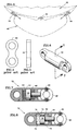
- FIG. 6 is a perspective view showing a cylindrical embodiment of the variable stiffness positioning link of the present invention.
- FIG. 7 is a cross-sectional schematic view taken in the direction of line 7-7 of FIG. 6 showing an embodiment of the variable stiffness positioning link, including an elastomeric damper, of the present invention.
- FIG. 8 is a cross-sectional schematic view similar to FIG. 7 showing another embodiment of the variable stiffness positioning link, including a fluid damper, of the present invention.
- FIG. 9 is a cross-sectional view of a rectangular embodiment of the variable stiffness positioning link of the present invention.
- FIG. 10 is an exploded view of the rectangular embodiment of the present invention shown in FIG. 9.
- a gas turbine engine 10 includes as its principal components a fan section 12, a compression section 14, a combustion section 16 and a turbine section 18.
- the compression and turbine sections each contain one or more stages of a compressor and turbine (not shown) which rotate about a central rotational axis 20.
- the principal components are circumscribed by an essentially cylindrical external case 22, which serves as a main structural support for the engine.
- the external case is usually constructed of individual case sections, such as case sections 24 and 26, which are joined together at bolted flanges such as flange 30.
- a gearbox 40 is mounted to the external case section 22.
- the gearbox 40 is mounted to the external case by locator 42 and side links 44.
- the locator 42 fastens the gearbox housing to the engine case to provide alignment of the gearbox relative to the engine.
- the side links of the prior art for the gearbox provide for an attachment of the gearbox to the engine case.
- the gearbox is also attached to the engine by the V-shaped link 48 axially forward of the locator 42 and side links 44.
- These mounting arrangements may be hard mounts, which connect the gearbox 40 to the engine case by essentially inflexible, immobile connections that transmit case deflections and distortions to the gearbox. During a blade loss event, loads transmitted throughout the engine can be extremely high.
- the hanger links 44 of the prior art only transmit axial (with respect to the link) loads from the engine case 22 to the gearbox 40.
- the links of the prior art provide a hard path to the gearbox, axial loads from engine case deflections are transmitted through the links to the gearbox.
- the axial loads transmitted from the engine case through the links to the gearbox may exceed the gearbox strength. This would compromise the integrity of the gearbox housing and accessories mounted on the gearbox.
- variable stiffness positioning links 52 of the present invention may be cylindrical or rectangular in cross-section (shown with respect to FIGS. 10 and 11).
- a variable stiffness positioning link 52 of the present invention includes a cylinder 54, a piston 56 slidably disposed within the cylinder and a connecting rod 58, which can preferably be formed integrally with the piston.
- the connecting rod 58 is connected to the cylinder 54 at one end thereof by shear pins 60, which are sized for sustaining a predetermined level of axial load.
- a chamber 62 is formed in the cylinder which is filled with an elastomer 64.
- variable stiffness links still transmit a percentage of the loads from the engine case to the gearbox.
- the movement of the piston in the chamber and the resultant compression of the elastomer in the chamber provides for a link having a lower stiffness level as compared to the links of the prior art, thus partially isolating the gearbox from engine case deflections and associated loads.
- variable stiffness positioning links 52 of the present invention includes damping fluid in the chamber 62 formed in the cylinder.
- the damping fluid 70 is normally a hydraulic fluid suitable for the temperature environment of the gearbox.
- a hole 72 in the piston 56 is sized to allow for the flow of the fluid 70 between the two reservoir portions 74, 76 of the chamber 62 partitioned by the piston 56 as the piston moves therein.
- the load levels exceed the predetermined load level of the shear pins 60
- the pins shear allowing the piston 56 to travel in the chamber 62.
- the movement of the piston is dampened by the fluid 70 disposed in the chamber.
- variable stiffness links of the present invention still transmit a smaller percentage of the loads from the engine case to the gearbox.
- the movement of the piston 56 in the fluid filled chamber 62 provides a link having a lower stiffness level than prior art and dissipates the energy transmitted therethrough.
- another embodiment of the present invention 52 includes a first member 80 having a recess 82 disposed therein.
- a slot 83 extends through the first member.
- a second member 84 has a chamber 86 disposed therein.
- the first 80 and second 84 members interfit with each other so that the slot 83 and the chamber 86 are generally aligned.
- the chamber has two pins 88, 90 positioned at the axial ends thereof.
- a piston 92 is received within the slot so it effectively divides the chamber into two equal portions. Both portions of the chamber are filled with a fluid 94 such as the damping fluid noted above.
- Shear pins 98 fit into corresponding holes 100 through the two members 80, 84.
- an axial load such as a tensile load
- the pins 98 will shear and allow the first member 80 to move relative to the second member 84.
- the fluid 94 in the chamber 86 will be forced to move through the hole 96 in the piston 92 from one portion of the chamber to the other.
- the pins 88 or 90 gradually stop the flow of the fluid through the hole in the piston and thereby prevents an abrupt termination of the movement of the fluid in the chamber.
- the fluid in the chamber provides damping of the portion of loads transmitted to the gearbox.
- the embodiment of the present invention shown in FIGS. 9 and 10 provides the details of the construction of the links and as such, details such as the spherical bearings 102 are shown.
- the spherical bearings eliminate the transmission of loads in all directions other than the axial direction.
- variable stiffness positioning links of the present invention partially disengage and result in the partial isolation of the gearbox from the deflections of the engine case.
- the bulk of the energy associated with the deflections of the engine case is not transmitted to the gearbox.
- the links of the present invention only transmit a percentage of the loads from the engine case to the gearbox. In the partially disengaged state, the links have a lower stiffness level as compared to the links of the prior art.
- the axial spring rate of the links is reduced to a second lower stiffness level at which the external gearbox can still be attached to the engine case without being compromised.
- the links thus have a load level at which the link transitions from a high spring rate to a second lower spring rate when a high rotor imbalance condition occurs.
- a primary advantage of the present invention gearbox link is a minimization of damage to the gearbox in the event of large rotor deflections and imbalance, such as a fan blade loss.
- a further advantage of the present invention is its ability to provide an appropriate restraining structure to the gearbox during both normal operation and a high rotor imbalance.
- Another advantage is the ease and cost of manufacturing and incorporating the variable stiffness links of the present invention. The simplicity of the structure and the use of economical materials allows for cost effective manufacturing processes. Further, current, prior art gearboxes can be retrofitted to include the gearbox links in a cost-effective manner.
- the present invention fits into the envelope of prior art gearboxes. By incorporating the present invention, engines limit damage to the gearbox housing during high rotor imbalance events.
- the links of the present invention may be implemented in a variety of ways.
- the links have been described as having a piston held by fasteners that shear when subjected to certain load levels. The movement of the piston is dampened by the presence of either an elastomer or a fluid that fills the chamber between the two opposed ends of the links.
- These embodiments are purely exemplary. Other configurations of links may be utilized in light of the teachings herein that use different damping material. Further, a rectangular and cylindrical embodiment of the links is disclosed. It should be understood that other shapes that fit the available envelope may be used.
Landscapes
- Engineering & Computer Science (AREA)
- General Engineering & Computer Science (AREA)
- Mechanical Engineering (AREA)
- Chemical & Material Sciences (AREA)
- Combustion & Propulsion (AREA)
- Health & Medical Sciences (AREA)
- Child & Adolescent Psychology (AREA)
- Structures Of Non-Positive Displacement Pumps (AREA)
- Transmission Devices (AREA)
- Control Of Turbines (AREA)
- General Details Of Gearings (AREA)
Applications Claiming Priority (2)
| Application Number | Priority Date | Filing Date | Title |
|---|---|---|---|
| US213685 | 1980-12-05 | ||
| US09/213,685 US6212974B1 (en) | 1998-12-17 | 1998-12-17 | Variable stiffness positioning link for a gearbox |
Publications (3)
| Publication Number | Publication Date |
|---|---|
| EP1010878A2 true EP1010878A2 (fr) | 2000-06-21 |
| EP1010878A3 EP1010878A3 (fr) | 2002-11-27 |
| EP1010878B1 EP1010878B1 (fr) | 2006-03-22 |
Family
ID=22796098
Family Applications (1)
| Application Number | Title | Priority Date | Filing Date |
|---|---|---|---|
| EP99309882A Expired - Lifetime EP1010878B1 (fr) | 1998-12-17 | 1999-12-08 | Turbine à gaz comprenant un dispositif de positionement à raideur variable pour la fixation d'un boîtier d'engrenage |
Country Status (4)
| Country | Link |
|---|---|
| US (1) | US6212974B1 (fr) |
| EP (1) | EP1010878B1 (fr) |
| JP (1) | JP2000179359A (fr) |
| DE (1) | DE69930485T2 (fr) |
Cited By (17)
| Publication number | Priority date | Publication date | Assignee | Title |
|---|---|---|---|---|
| EP1607330A1 (fr) * | 2004-06-14 | 2005-12-21 | Rolls-Royce Plc | Bâti moteur |
| WO2007064388A1 (fr) * | 2005-12-01 | 2007-06-07 | Hamilton Sundstrand Corporation | Monture de composant auxiliaire de turbine a gaz |
| WO2008150213A1 (fr) * | 2007-06-08 | 2008-12-11 | Volvo Aero Corporation | Élément de montage pour moteur de turbine à gaz et structure et aéronef comportant un tel élément de montage |
| EP2372129A2 (fr) * | 2010-03-30 | 2011-10-05 | United Technologies Corporation | Arrangement de montage pour les accessoires de turbines à gaz |
| WO2014081500A2 (fr) | 2012-09-28 | 2014-05-30 | United Technologies Corporation | Supports de composants auxiliaires |
| WO2014140441A1 (fr) * | 2013-03-14 | 2014-09-18 | Snecma | Boite d'engrenages en v pour entraînement d'équipements de turbomachine |
| EP3193038A1 (fr) * | 2016-01-14 | 2017-07-19 | United Technologies Corporation | Échangeur de chaleur pour air de refroidissement refroidi au moyen de régulateur réglable |
| EP3219963A1 (fr) * | 2016-03-14 | 2017-09-20 | Hamilton Sundstrand Corporation | Liaison de montage de boîtes de vitesses semi-fusible à deux degrés de contrainte |
| EP3219962A1 (fr) * | 2016-03-14 | 2017-09-20 | Hamilton Sundstrand Corporation | Liaison de montage semi-fusible à un degré de contrainte pour boîte de vitesses |
| GB2551627A (en) * | 2016-04-25 | 2017-12-27 | Hamilton Sundstrand Corp | Fusible link with coulomb damping |
| US10253695B2 (en) | 2015-08-14 | 2019-04-09 | United Technologies Corporation | Heat exchanger for cooled cooling air with adjustable damper |
| US10267365B2 (en) | 2015-12-11 | 2019-04-23 | General Electric Company | Power gearbox pin arrangement |
| US10287982B2 (en) | 2015-08-14 | 2019-05-14 | United Technologies Corporation | Folded heat exchanger for cooled cooling air |
| WO2019140437A1 (fr) * | 2018-01-15 | 2019-07-18 | Lord Corporation | Système de support pour moteur et éléments réduisant la transmission de force et mouvement statique réduit et procédés associés |
| US10816086B2 (en) | 2017-08-14 | 2020-10-27 | General Electric Company | Power gearbox gear arrangement |
| CN112498531A (zh) * | 2020-11-30 | 2021-03-16 | 储华 | 一种多级缓冲防颠簸自行车坐垫杆 |
| WO2022023103A1 (fr) * | 2020-07-29 | 2022-02-03 | Rolls-Royce Deutschland Ltd & Co Kg | Turbine à gaz dotée d'un relais d'accessoires |
Families Citing this family (35)
| Publication number | Priority date | Publication date | Assignee | Title |
|---|---|---|---|---|
| US6330985B1 (en) * | 2000-06-30 | 2001-12-18 | General Electric Company | Link component for aircraft engine mounting systems |
| US6669393B2 (en) * | 2001-10-10 | 2003-12-30 | General Electric Co. | Connector assembly for gas turbine engines |
| CN100408910C (zh) * | 2002-05-21 | 2008-08-06 | 贝尔直升机泰克斯特龙公司 | 可变刚度支撑件 |
| DE10249517B4 (de) * | 2002-10-23 | 2008-11-20 | Eurocopter Deutschland Gmbh | Stoßabsorbierende, lastbegrenzende Verbindungsvorrichtung sowie Drehflügelflugzeug mit einer solchen Verbindungsvorrichtung |
| US7093996B2 (en) * | 2003-04-30 | 2006-08-22 | General Electric Company | Methods and apparatus for mounting a gas turbine engine |
| RU2313676C2 (ru) * | 2005-10-26 | 2007-12-27 | Открытое акционерное общество "Авиадвигатель" | Устройство соединения силового корпуса и коробки приводных агрегатов газотурбинного двигателя |
| FR2901315B1 (fr) * | 2006-05-19 | 2010-09-10 | Hispano Suiza Sa | Boitier d'accessoires dans un moteur d'avion tel qu'un turboreacteur |
| US9091214B2 (en) * | 2007-06-28 | 2015-07-28 | United Technologies Corporation | Reduced gearbox size by separate electrically powered engine oil system |
| US8256750B2 (en) * | 2009-02-18 | 2012-09-04 | Honeywell International Inc. | Vibration isolation mounting assembly |
| US8272786B2 (en) * | 2009-02-18 | 2012-09-25 | Honeywell International Inc. | Vibration isolation mounting assembly |
| US8702377B2 (en) | 2010-06-23 | 2014-04-22 | Honeywell International Inc. | Gas turbine engine rotor tip clearance and shaft dynamics system and method |
| US8561501B2 (en) | 2011-05-31 | 2013-10-22 | United Technologies Corporation | Gearbox mount bracket |
| US8529197B1 (en) * | 2012-03-28 | 2013-09-10 | United Technologies Corporation | Gas turbine engine fan drive gear system damper |
| US9016068B2 (en) | 2012-07-13 | 2015-04-28 | United Technologies Corporation | Mid-turbine frame with oil system mounts |
| US9046041B2 (en) | 2012-09-25 | 2015-06-02 | Pratt & Whitney Canada Corp. | Gearbox positioning device |
| US9500133B2 (en) | 2012-12-23 | 2016-11-22 | United Technologies Corporation | Mount with an axial upstream linkage for connecting a gearbox to a turbine engine case |
| US9777639B2 (en) | 2012-12-23 | 2017-10-03 | United Technologies Corporation | Turbine engine gearbox mount with multiple fuse joints |
| GB201314667D0 (en) * | 2013-08-16 | 2013-10-02 | Rolls Royce Plc | A panel attachment system |
| US20150056001A1 (en) * | 2013-08-22 | 2015-02-26 | Powers and Sons, LLC | Mechanical overload fuse for steering linkage |
| WO2015041855A1 (fr) | 2013-09-19 | 2015-03-26 | United Technologies Corporation | Support antichoc pour carter de moteur d'avion |
| FR3014953B1 (fr) | 2013-12-12 | 2016-01-01 | Snecma | Turbomachine d'aeronef comportant un echangeur de chaleur et une boite d'engrenages en v |
| GB201408129D0 (en) * | 2014-05-08 | 2014-06-25 | Rolls Royce Plc | Stub shaft |
| US10107378B2 (en) | 2015-11-03 | 2018-10-23 | General Electric Company | Systems and methods for a gas turbine engine with combined multi-directional gearbox deflection limiters and dampers |
| US9677659B1 (en) | 2016-01-28 | 2017-06-13 | General Electric Company | Gearbox planet attenuation spring damper |
| US10274071B2 (en) | 2016-01-28 | 2019-04-30 | General Electric Company | Gearbox planet squeeze film damper |
| US10113633B2 (en) | 2016-01-28 | 2018-10-30 | General Electric Company | Gearbox planet squeeze film damper |
| US10215100B2 (en) | 2016-03-14 | 2019-02-26 | Hamilton Sundstrand Corporation | One degree-of-constraint semi-fusible gearbox mounting link |
| US10006373B2 (en) | 2016-03-14 | 2018-06-26 | Hamilton Sundstrand Coporation | Two degree-of-constraint semi-fusible gearbox mounting link |
| EP3573890B1 (fr) * | 2016-12-20 | 2023-07-19 | Bombardier Inc. | Liaison de poussée avec absorbeur accordé |
| US11015698B2 (en) * | 2018-10-01 | 2021-05-25 | Hamilton Sundstrand Corporation | Gearbox mounting link |
| US11739645B2 (en) * | 2020-09-30 | 2023-08-29 | General Electric Company | Vibrational dampening elements |
| US11639669B2 (en) | 2021-02-08 | 2023-05-02 | General Electric Company | Systems and methods for selectively disconnecting embedded electrical machines in gas turbine engines |
| GB202301053D0 (en) | 2023-01-25 | 2023-03-08 | Rolls Royce Plc | Mounting assembly for gas turbine engine |
| US12515807B2 (en) | 2024-01-19 | 2026-01-06 | Pratt & Whitney Canada Corp. | Bolted connection between mounting bracket and aircraft engine case(s) |
| US20260022668A1 (en) * | 2024-07-16 | 2026-01-22 | Rtx Corporation | Gearbox arrangement for dual spool engine accessories |
Family Cites Families (26)
| Publication number | Priority date | Publication date | Assignee | Title |
|---|---|---|---|---|
| US2667348A (en) * | 1952-02-05 | 1954-01-26 | Dowty Equipment Ltd | Resilient telescopic device |
| US2978869A (en) * | 1956-11-01 | 1961-04-11 | Bristol Siddeley Engines Ltd | Engine accessory mounting arrangements |
| US2951395A (en) | 1958-09-17 | 1960-09-06 | United Aircraft Corp | Flexible gearbox mounting |
| US3568806A (en) | 1969-08-27 | 1971-03-09 | Us Navy | Torsion yield shock mount |
| US3794277A (en) * | 1972-08-14 | 1974-02-26 | A Smedley | Earthquake resistant support |
| US3836100A (en) * | 1973-06-13 | 1974-09-17 | United Aircraft Corp | Engine mounting arrangement |
| JPS54135437A (en) * | 1978-04-11 | 1979-10-20 | Ohbayashigumi Ltd | Eathquake-protection device |
| US4301989A (en) | 1979-06-29 | 1981-11-24 | Kallenbach Ralph M | Pipe whip restraint system and energy absorbing device therefor |
| DE3026766A1 (de) * | 1980-07-15 | 1982-01-28 | Hans 8898 Schrobenhausen Sorcan | Gegen koerperschall gegenueber einer starren halterung abgeschirmt gelagertes schwingungsfaehiges system |
| FR2511103A1 (fr) * | 1981-08-10 | 1983-02-11 | Aerospatiale | Composants munis d'un dispositif d'absorption d'energie par deformation plastique et/ou de limitation d'effort, et trains d'atterrissage d'aerodynes equipes de tels composants |
| US4517913A (en) | 1984-02-03 | 1985-05-21 | Baldt Incorporated | Mooring system with frangible links |
| JPH0435626Y2 (fr) * | 1987-05-22 | 1992-08-24 | ||
| JP2805345B2 (ja) * | 1989-07-18 | 1998-09-30 | オイレス工業株式会社 | 構造物用エネルギー吸収装置 |
| US5031396A (en) * | 1989-12-01 | 1991-07-16 | United Technologies Corporation | Premounting retainer for a gas turbine engine |
| DE69012071T2 (de) | 1989-12-05 | 1995-04-13 | Rolls Royce Plc | Ausfallsichere Haltevorrichtung für Treibwerke. |
| US5176339A (en) * | 1991-09-30 | 1993-01-05 | Lord Corporation | Resilient pivot type aircraft mounting |
| US5275357A (en) * | 1992-01-16 | 1994-01-04 | General Electric Company | Aircraft engine mount |
| US5277382A (en) | 1992-10-13 | 1994-01-11 | General Electric Company | Aircraft engine forward mount |
| US5303880A (en) | 1992-10-28 | 1994-04-19 | General Electric Company | Aircraft engine pin mount |
| US5529276A (en) | 1993-06-21 | 1996-06-25 | Breakaway Products, Inc. | Frangible guy attachment for utility poles |
| US5813674A (en) | 1993-08-10 | 1998-09-29 | United Technologies Corporation | Reverse pressure tolerant seal means |
| US5524847A (en) | 1993-09-07 | 1996-06-11 | United Technologies Corporation | Nacelle and mounting arrangement for an aircraft engine |
| US5435124A (en) | 1994-08-10 | 1995-07-25 | United Technologies Corporation | Mounting bracket for an aircraft engine accessory |
| US5649417A (en) | 1995-03-24 | 1997-07-22 | The Boeing Company | Fail-safe engine mount system |
| US5725181A (en) | 1996-05-01 | 1998-03-10 | The Boeing Company | Aircraft engine thrust mount |
| US5971375A (en) * | 1996-11-26 | 1999-10-26 | Trw Inc. | Isolator apparatus for multi-dimensional vibrational disturbances |
-
1998
- 1998-12-17 US US09/213,685 patent/US6212974B1/en not_active Expired - Lifetime
-
1999
- 1999-09-08 JP JP11253938A patent/JP2000179359A/ja active Pending
- 1999-12-08 DE DE69930485T patent/DE69930485T2/de not_active Expired - Lifetime
- 1999-12-08 EP EP99309882A patent/EP1010878B1/fr not_active Expired - Lifetime
Non-Patent Citations (1)
| Title |
|---|
| None |
Cited By (39)
| Publication number | Priority date | Publication date | Assignee | Title |
|---|---|---|---|---|
| EP1607330A1 (fr) * | 2004-06-14 | 2005-12-21 | Rolls-Royce Plc | Bâti moteur |
| WO2007064388A1 (fr) * | 2005-12-01 | 2007-06-07 | Hamilton Sundstrand Corporation | Monture de composant auxiliaire de turbine a gaz |
| GB2444692A (en) * | 2005-12-01 | 2008-06-11 | Hamilton Sundstrand Corp | Gas turbine engine auxiliary component mount |
| GB2444692B (en) * | 2005-12-01 | 2010-09-29 | Hamilton Sundstrand Corp | Gas turbine engine auxiliary component mount |
| DE112006003297B4 (de) | 2005-12-01 | 2023-02-09 | Hamilton Sundstrand Corporation | Befestigung von Gasturbinentriebwerks-Zusatzkomponenten |
| US8104736B2 (en) | 2005-12-01 | 2012-01-31 | Hamilton Sundstrand Corporation | Gas turbine engine auxiliary component mount |
| CN101321940B (zh) * | 2005-12-01 | 2014-05-07 | 哈米尔顿森德斯特兰德公司 | 燃气涡轮发动机的辅助部件安装 |
| WO2008150213A1 (fr) * | 2007-06-08 | 2008-12-11 | Volvo Aero Corporation | Élément de montage pour moteur de turbine à gaz et structure et aéronef comportant un tel élément de montage |
| WO2008150202A1 (fr) * | 2007-06-08 | 2008-12-11 | Volvo Aero Corporation | Structure de transfert de charges au niveau d'une turbine à gaz, et turbine et aéronef comportant une telle structure |
| EP2372129A2 (fr) * | 2010-03-30 | 2011-10-05 | United Technologies Corporation | Arrangement de montage pour les accessoires de turbines à gaz |
| WO2014081500A2 (fr) | 2012-09-28 | 2014-05-30 | United Technologies Corporation | Supports de composants auxiliaires |
| US9982605B2 (en) | 2012-09-28 | 2018-05-29 | United Technologies Corporation | Auxiliary component mount including a fusible region configured to break at a predetermined load |
| EP2901067A4 (fr) * | 2012-09-28 | 2016-05-25 | United Technologies Corp | Supports de composants auxiliaires |
| WO2014140441A1 (fr) * | 2013-03-14 | 2014-09-18 | Snecma | Boite d'engrenages en v pour entraînement d'équipements de turbomachine |
| FR3003323A1 (fr) * | 2013-03-14 | 2014-09-19 | Snecma | Fixation d'une boite d'engrenages en v sur une turbomachine |
| US10054001B2 (en) | 2013-03-14 | 2018-08-21 | Snecma | V-shaped gearbox for driving turbomachine equipment |
| US11572928B2 (en) | 2015-08-14 | 2023-02-07 | Raytheon Technologies Corporation | Heat exchanger for cooled cooling air with adjustable damper |
| US11492973B2 (en) | 2015-08-14 | 2022-11-08 | Raytheon Technologies Corporation | Folded heat exchanger for cooled cooling air |
| US10287982B2 (en) | 2015-08-14 | 2019-05-14 | United Technologies Corporation | Folded heat exchanger for cooled cooling air |
| US10253695B2 (en) | 2015-08-14 | 2019-04-09 | United Technologies Corporation | Heat exchanger for cooled cooling air with adjustable damper |
| US10267365B2 (en) | 2015-12-11 | 2019-04-23 | General Electric Company | Power gearbox pin arrangement |
| EP3193038A1 (fr) * | 2016-01-14 | 2017-07-19 | United Technologies Corporation | Échangeur de chaleur pour air de refroidissement refroidi au moyen de régulateur réglable |
| EP3567271A1 (fr) * | 2016-01-14 | 2019-11-13 | United Technologies Corporation | Échangeur de chaleur pour air de refroidissement refroidi au moyen de régulateur réglable |
| US10012149B2 (en) | 2016-03-14 | 2018-07-03 | Hamilton Sundstrand Corporation | Two degree-of-constraint semi-fusible gearbox mounting link |
| EP3219963A1 (fr) * | 2016-03-14 | 2017-09-20 | Hamilton Sundstrand Corporation | Liaison de montage de boîtes de vitesses semi-fusible à deux degrés de contrainte |
| US10066552B2 (en) | 2016-03-14 | 2018-09-04 | Hamilton Sundstrand Corporation | One degree-of-constraint semi-fusible gearbox mounting link |
| EP3219962A1 (fr) * | 2016-03-14 | 2017-09-20 | Hamilton Sundstrand Corporation | Liaison de montage semi-fusible à un degré de contrainte pour boîte de vitesses |
| GB2551627A (en) * | 2016-04-25 | 2017-12-27 | Hamilton Sundstrand Corp | Fusible link with coulomb damping |
| US10132245B2 (en) | 2016-04-25 | 2018-11-20 | Hamilton Sundstrand Corporation | Fusible link with coulomb damping |
| GB2551627B (en) * | 2016-04-25 | 2021-07-07 | Hamilton Sundstrand Corp | Fusible link with coulomb damping |
| US10816086B2 (en) | 2017-08-14 | 2020-10-27 | General Electric Company | Power gearbox gear arrangement |
| US11698129B2 (en) | 2017-08-14 | 2023-07-11 | General Electric Company | Power gearbox gear arrangement |
| US12117075B2 (en) | 2017-08-14 | 2024-10-15 | General Electric Company | Power gearbox gear arrangement |
| US11542023B2 (en) | 2018-01-15 | 2023-01-03 | Lord Corporation | Engine mount system and elements for reduced force transmission and reduced static motion and associated methods |
| WO2019140437A1 (fr) * | 2018-01-15 | 2019-07-18 | Lord Corporation | Système de support pour moteur et éléments réduisant la transmission de force et mouvement statique réduit et procédés associés |
| US11787552B2 (en) | 2018-01-15 | 2023-10-17 | Lord Corporation | Engine mount system and elements for reduced force transmission and reduced static motion |
| WO2022023103A1 (fr) * | 2020-07-29 | 2022-02-03 | Rolls-Royce Deutschland Ltd & Co Kg | Turbine à gaz dotée d'un relais d'accessoires |
| US11867074B2 (en) | 2020-07-29 | 2024-01-09 | Rolls-Royce Deutschland Ltd & Co. Kg | Gas turbine engine having an accessory gearbox |
| CN112498531A (zh) * | 2020-11-30 | 2021-03-16 | 储华 | 一种多级缓冲防颠簸自行车坐垫杆 |
Also Published As
| Publication number | Publication date |
|---|---|
| EP1010878A3 (fr) | 2002-11-27 |
| DE69930485D1 (de) | 2006-05-11 |
| DE69930485T2 (de) | 2006-11-09 |
| JP2000179359A (ja) | 2000-06-27 |
| US6212974B1 (en) | 2001-04-10 |
| EP1010878B1 (fr) | 2006-03-22 |
Similar Documents
| Publication | Publication Date | Title |
|---|---|---|
| US6212974B1 (en) | Variable stiffness positioning link for a gearbox | |
| EP1008738B1 (fr) | Support de boitier d'engrenage avec élasticité réglée | |
| EP1010879B1 (fr) | Dispositif de positionement pour une fixation d'un boítier d'engrenages | |
| EP2559883B1 (fr) | Fixation de la boîte d'engrenages de moteur à turbine à gaz | |
| US6357220B1 (en) | Gearbox accessory mount | |
| JP5591944B2 (ja) | ターボジェットのファンコンパートメント用中間ケーシングへのagbの取り付け | |
| US8943840B2 (en) | Mounting assembly | |
| EP3219962B1 (fr) | Liaison de montage semi-fusible à un degré de contrainte pour boîte de vitesses | |
| EP1157925B1 (fr) | Montage de reprise de poussée d'un moteur avec amortissement | |
| US20160017811A1 (en) | Gearbox mounting assembly | |
| US10132245B2 (en) | Fusible link with coulomb damping | |
| US20070056292A1 (en) | Auxiliary power unit case flange to cone bolt adapter | |
| EP3438421A1 (fr) | Ensemble de montage | |
| US12479586B2 (en) | Fusible mounting assembly for gas turbine engine | |
| US20260022668A1 (en) | Gearbox arrangement for dual spool engine accessories | |
| EP4400705A1 (fr) | Couvercle de boîte de vitesses d'accessoires à élément de liaison plan | |
| FR3162471A1 (fr) | Suspension d’un organe de turbomachine à la structure de la turbomachine |
Legal Events
| Date | Code | Title | Description |
|---|---|---|---|
| PUAI | Public reference made under article 153(3) epc to a published international application that has entered the european phase |
Free format text: ORIGINAL CODE: 0009012 |
|
| AK | Designated contracting states |
Kind code of ref document: A2 Designated state(s): AT BE CH CY DE DK ES FI FR GB GR IE IT LI LU MC NL PT SE |
|
| AX | Request for extension of the european patent |
Free format text: AL;LT;LV;MK;RO;SI |
|
| PUAL | Search report despatched |
Free format text: ORIGINAL CODE: 0009013 |
|
| AK | Designated contracting states |
Kind code of ref document: A3 Designated state(s): AT BE CH CY DE DK ES FI FR GB GR IE IT LI LU MC NL PT SE |
|
| AX | Request for extension of the european patent |
Free format text: AL;LT;LV;MK;RO;SI |
|
| RIC1 | Information provided on ipc code assigned before grant |
Free format text: 7F 02C 7/32 A, 7F 01D 21/04 B, 7F 16F 9/18 B, 7F 16F 7/12 B, 7F 16F 9/30 B |
|
| 17P | Request for examination filed |
Effective date: 20021218 |
|
| 17Q | First examination report despatched |
Effective date: 20030403 |
|
| AKX | Designation fees paid |
Designated state(s): DE FR GB |
|
| GRAP | Despatch of communication of intention to grant a patent |
Free format text: ORIGINAL CODE: EPIDOSNIGR1 |
|
| RTI1 | Title (correction) |
Free format text: GAS TURBINE ENGINE HAVING A VARIABLE STIFFNESS POSITIONING LINK FOR A GEARBOX |
|
| GRAS | Grant fee paid |
Free format text: ORIGINAL CODE: EPIDOSNIGR3 |
|
| GRAA | (expected) grant |
Free format text: ORIGINAL CODE: 0009210 |
|
| AK | Designated contracting states |
Kind code of ref document: B1 Designated state(s): DE FR GB |
|
| REG | Reference to a national code |
Ref country code: GB Ref legal event code: FG4D |
|
| REF | Corresponds to: |
Ref document number: 69930485 Country of ref document: DE Date of ref document: 20060511 Kind code of ref document: P |
|
| ET | Fr: translation filed | ||
| PLBE | No opposition filed within time limit |
Free format text: ORIGINAL CODE: 0009261 |
|
| STAA | Information on the status of an ep patent application or granted ep patent |
Free format text: STATUS: NO OPPOSITION FILED WITHIN TIME LIMIT |
|
| 26N | No opposition filed |
Effective date: 20061227 |
|
| PGFP | Annual fee paid to national office [announced via postgrant information from national office to epo] |
Ref country code: FR Payment date: 20081205 Year of fee payment: 10 |
|
| REG | Reference to a national code |
Ref country code: FR Ref legal event code: ST Effective date: 20100831 |
|
| PG25 | Lapsed in a contracting state [announced via postgrant information from national office to epo] |
Ref country code: FR Free format text: LAPSE BECAUSE OF NON-PAYMENT OF DUE FEES Effective date: 20091231 |
|
| PGFP | Annual fee paid to national office [announced via postgrant information from national office to epo] |
Ref country code: DE Payment date: 20121205 Year of fee payment: 14 |
|
| PGFP | Annual fee paid to national office [announced via postgrant information from national office to epo] |
Ref country code: GB Payment date: 20121205 Year of fee payment: 14 |
|
| REG | Reference to a national code |
Ref country code: DE Ref legal event code: R119 Ref document number: 69930485 Country of ref document: DE |
|
| GBPC | Gb: european patent ceased through non-payment of renewal fee |
Effective date: 20131208 |
|
| REG | Reference to a national code |
Ref country code: DE Ref legal event code: R119 Ref document number: 69930485 Country of ref document: DE Effective date: 20140701 |
|
| PG25 | Lapsed in a contracting state [announced via postgrant information from national office to epo] |
Ref country code: DE Free format text: LAPSE BECAUSE OF NON-PAYMENT OF DUE FEES Effective date: 20140701 |
|
| PG25 | Lapsed in a contracting state [announced via postgrant information from national office to epo] |
Ref country code: GB Free format text: LAPSE BECAUSE OF NON-PAYMENT OF DUE FEES Effective date: 20131208 |