EP2372129A2 - Arrangement de montage pour les accessoires de turbines à gaz - Google Patents
Arrangement de montage pour les accessoires de turbines à gaz Download PDFInfo
- Publication number
- EP2372129A2 EP2372129A2 EP20110160405 EP11160405A EP2372129A2 EP 2372129 A2 EP2372129 A2 EP 2372129A2 EP 20110160405 EP20110160405 EP 20110160405 EP 11160405 A EP11160405 A EP 11160405A EP 2372129 A2 EP2372129 A2 EP 2372129A2
- Authority
- EP
- European Patent Office
- Prior art keywords
- gas turbine
- turbine engine
- accessory
- gearbox
- engine
- Prior art date
- Legal status (The legal status is an assumption and is not a legal conclusion. Google has not performed a legal analysis and makes no representation as to the accuracy of the status listed.)
- Ceased
Links
- 239000000446 fuel Substances 0.000 claims description 16
- 239000012530 fluid Substances 0.000 claims description 10
- 238000011144 upstream manufacturing Methods 0.000 claims description 5
- 238000010438 heat treatment Methods 0.000 claims 2
- 239000010687 lubricating oil Substances 0.000 claims 1
- 238000009434 installation Methods 0.000 abstract description 3
- 238000012423 maintenance Methods 0.000 description 5
- 238000009428 plumbing Methods 0.000 description 3
- 238000006073 displacement reaction Methods 0.000 description 2
- 239000000284 extract Substances 0.000 description 2
- 238000005461 lubrication Methods 0.000 description 2
- 239000000203 mixture Substances 0.000 description 2
- 238000000926 separation method Methods 0.000 description 2
- RZVHIXYEVGDQDX-UHFFFAOYSA-N 9,10-anthraquinone Chemical compound C1=CC=C2C(=O)C3=CC=CC=C3C(=O)C2=C1 RZVHIXYEVGDQDX-UHFFFAOYSA-N 0.000 description 1
- 238000005452 bending Methods 0.000 description 1
- 238000006243 chemical reaction Methods 0.000 description 1
- 230000000295 complement effect Effects 0.000 description 1
- 230000037406 food intake Effects 0.000 description 1
- 230000000116 mitigating effect Effects 0.000 description 1
- 238000012986 modification Methods 0.000 description 1
- 230000004048 modification Effects 0.000 description 1
- 239000007858 starting material Substances 0.000 description 1
Images


Classifications
-
- F—MECHANICAL ENGINEERING; LIGHTING; HEATING; WEAPONS; BLASTING
- F02—COMBUSTION ENGINES; HOT-GAS OR COMBUSTION-PRODUCT ENGINE PLANTS
- F02C—GAS-TURBINE PLANTS; AIR INTAKES FOR JET-PROPULSION PLANTS; CONTROLLING FUEL SUPPLY IN AIR-BREATHING JET-PROPULSION PLANTS
- F02C7/00—Features, components parts, details or accessories, not provided for in, or of interest apart form groups F02C1/00 - F02C6/00; Air intakes for jet-propulsion plants
- F02C7/32—Arrangement, mounting, or driving, of auxiliaries
-
- F—MECHANICAL ENGINEERING; LIGHTING; HEATING; WEAPONS; BLASTING
- F01—MACHINES OR ENGINES IN GENERAL; ENGINE PLANTS IN GENERAL; STEAM ENGINES
- F01D—NON-POSITIVE DISPLACEMENT MACHINES OR ENGINES, e.g. STEAM TURBINES
- F01D15/00—Adaptations of machines or engines for special use; Combinations of engines with devices driven thereby
- F01D15/12—Combinations with mechanical gearing
-
- Y—GENERAL TAGGING OF NEW TECHNOLOGICAL DEVELOPMENTS; GENERAL TAGGING OF CROSS-SECTIONAL TECHNOLOGIES SPANNING OVER SEVERAL SECTIONS OF THE IPC; TECHNICAL SUBJECTS COVERED BY FORMER USPC CROSS-REFERENCE ART COLLECTIONS [XRACs] AND DIGESTS
- Y02—TECHNOLOGIES OR APPLICATIONS FOR MITIGATION OR ADAPTATION AGAINST CLIMATE CHANGE
- Y02T—CLIMATE CHANGE MITIGATION TECHNOLOGIES RELATED TO TRANSPORTATION
- Y02T50/00—Aeronautics or air transport
- Y02T50/60—Efficient propulsion technologies, e.g. for aircraft
Definitions
- This invention relates generally to gas turbine engines and particularly to a mounting arrangement for gas turbine engine accessories such as electrical generators, pumps and the like and gearboxes therefor.
- Gas turbine engines particularly those which power aircraft, are often provided with accessories such as electrical generators, pumps, air turbines and the like, which are required for operation of the engine and an associated aircraft.
- electrical generators are provided to generate electrical power needed for electrical systems in the engine itself, such as electronic engine controls and variable pitch vanes and the like.
- Accessory pumps are provided to pressurize lubrication systems within the engine and hydraulically powered engine systems such as thrust reversers and the like and aircraft systems such as adjustable flight control surfaces.
- Air turbines driven by compressed air from, for example, an external source provide starting power to the engine. It is common practice to mechanically connect such accessory generator air turbines and pumps to the engine by means of an accessory gearbox which is itself mechanically connected to the rotational shaft of the engine and mounted on the engine stator.
- mounting accessories such as pumps and generators at such a forward location requires electrical and fluid lines running from such accessories to traverse significant longitudinal distances from the accessory to a pylon on which the engine is mounted to an associated aircraft, the pylon providing the normal route for the extension of such lines from the engine to systems on the aircraft for which electrical and/or hydraulic power is produced by such accessories.
- Mounting accessories and gearboxes therefor on the fan case of a gas turbine engine also places such components at risk for damage in the event of breakage or other separation of fan blades from the fan hub in the event of encounters with foreign objects such as ice, birds, or other foreign objects.
- mounting the accessories and gearbox at such an engine's forwardmost position at the fan case within the nacelle usually restricts possible rearward-facing mounting positions, reducing the available area for component removal and placement.
- an accessory gearbox for a gas turbine engine is mounted on that portion of the engine case which surrounds the engine core and accessory components which mechanically connect to the engine by means of the gearbox, are mounted on the gearbox such that the accessory components extend from the gearbox in a direction generally circumferentially tangent to the engine case.
- the location of the accessories and gearbox on the core case rather than the fan case of the engine reduces the risk of damage to such components from the separation of fan blades from a hub therefor in the event of a bird strike or the ingestion of ice or other foreign manner into the engine.
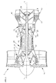
- a turbofan gas turbine engine 5 has a longitudinal axis 7 about which the rotors 8 of the engine rotate.
- a fan 10 disposed at the engine inlet draws air into the engine.
- a low pressure compressor 15 located immediately downstream of fan 10 compresses air exhausted from fan 10 and a high pressure compressor 20 located immediately downstream of low pressure compressor 15, further compresses air received therefrom and exhausts such air to combustors 25 disposed immediately downstream of high pressure compressor 20.
- Combustors 25 receive fuel through fuel lines 30 and ignite the fuel/air mixture.
- the burning fuel-air mixture (working medium fluid) flows axially to a high pressure turbine 35 which extracts energy from the working medium fluid and in so doing, rotates hollow shaft 37, thereby driving the rotor of high pressure compressor 20.
- the working medium fluid exiting the high pressure turbine 35 then enters low pressure turbine 40, which extracts further energy from the working medium fluid.
- the low pressure turbine rotor provides power to drive the fan 10 and low pressure compressor 15 via low pressure shaft 42, which is disposed interiorly of the shaft 37, coaxial thereto.
- Working medium fluid exiting the low pressure turbine 40 provides axial thrust for powering an associated aircraft (not shown) or a free turbine (also not shown).
- Bearings 43, 45, 50 and 53 radially support the concentric high pressure and low pressure turbine shafts from separate frame structures 52, 54, 55 and 56 respectively, attached to engine case 57, which defines the outer boundary of the engine's stator which circumscribes rotors 8.
- the present invention is also well suited for mid-turbine frame engine architectures wherein the upstream bearings for the low and high pressure turbines are mounted on a common frame structure disposed longitudinally (axially) between the high and low pressure turbines.
- an accessory gearbox 60 is mounted on the engine case 57 at that portion of the case which surrounds the core of the engine (high pressure compressor, combustor and turbine).
- the core case is typically of a smaller diameter than that portion of the engine case which surrounds the fan and low pressure turbine, thereby allowing enhanced access to gearbox 60 and accessories mounted thereon through openings in the engine nacelle (not shown) which surround the engine.
- accessory gearbox 60 is mounted on case 57 at a longitudinal location upstream of combustor 25, for example, at a longitudinal location corresponding to high pressure compressor 20.
- gearbox 60 includes a longitudinal axis 62 which is generally parallel to longitudinal axis 7 of the engine itself.
- Gearbox 60 is provided with internal gearing, portions of which are shown at 65 ( FIG. 5 ).
- the details of such gearing will depend upon the torque and power characteristics of such accessories as well as the configuration of the mechanical connections thereto and the speed at which accessory gearbox 60 is driven by engine 5.
- the present invention may be employed with a variety of gas turbine engines and engine accessories. Therefore, for clarity of description and illustration, details of internal gearing 65 are not shown herein, but will suggest themselves to those skilled in the art based upon the characteristics of the engine and accessories with which the present invention is employed.
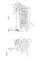
- gearbox 60 As best seen in FIGS. 3 and 5 , mechanical input power is provided to gearbox 60 through shaft 70, driven by the engine rotor, being connected thereto through suitable gearing (not shown) internally of the engine.
- FIG. 3 a number of accessories employed in the auxiliary systems of engine 5 set forth hereinabove are shown mounted on the accessory gearbox 60.
- those accessories with which the mounting arrangement of the present invention may be employed are hydraulic pump 75 which provides hydraulic fluid pressure to hydraulically operated systems on engine 5 and an associated aircraft (not shown) and oil pump 80 which pressurizes lubrication systems employed in the engine, such as, for the bearings thereof as well as any similar systems on the associated aircraft.
- Alternator 85 provides electrical power to electrical systems on the engine or associated with the aircraft, and fuel pump 90 pumps fuel from a reservoir thereof (not shown) to combustors 25. It will be understood that these accessories may be part of modules which include other associated equipment.
- fuel pump 90 may be part of a module which also includes a fuel filter as well as associated manifolding and fuel metering valving.
- an air turbine starter 100 which receives pressurized air through conduit 105 for providing input power to gearbox 60 upon engine starting.
- the accessories enumerated hereinabove are mounted on a pair of mounting surfaces 110, 115, angularly offset by approximately 110° from one another. Input and output shafts of the accessories illustrated in FIG. 3 and described hereinabove connect to internal gearing 65 through openings in the mounting surfaces, the accessories being mounted to the mounting surfaces by any suitable means such as bolted connections and the like.
- the angular offset of mounting surfaces 110 and 115 causes the accessory components mounted thereon to extend from the gearbox in directions generally circumferentially tangent to engine core case 57.
- accessory gearbox 60 is mounted on the engine case by means of a forward mounting clevis 125 comprising a pair of spaced lugs 130 which receive thereinbetween a complementary lug (not shown) on the engine case, the clevis lugs and engine case lug being pinned together by pin 135.
- Gearbox 60 is connected to the engine case at the aft end of the gearbox by one or more extensible links 140 which connect at the inner ends thereof to the engine case and at the outer ends thereof to a bracket 145 at the aft end of the gearbox housing.
- the pinned connection of the gearbox housing to the engine case at the forward end of the gearbox and the connection at the rear end of the gearbox to extensible links 140 allow limited pivotal movement of the gearbox with respect to the engine case to accommodate torsional reaction of the gearbox housing to loads thereon from the operation of internal gearing 65.
- the ability of the gearbox to pivotally move with respect to the engine case also isolates the gearbox from mechanical loads on the engine case due to, for example, engine shaft bending or the like, thereby mitigating damage to the gearbox from such events.
- the accessory and gearbox mounting arrangement of the present invention allow the accessories to be removed from the gearbox and reinstalled thereon in directions generally tangential to the circumference of the engine case in a compact arrangement minimizing the amount of radical free space outside of the engine case required for such removal and installation. Minimizing the radial free space required for such accessory installation and removal minimizes the required size of an associated nacelle, thereby reducing the weight thereof Mounting the accessory gearbox on the engine core case reduces the risk of damage to the gearbox and accessories from fan blades which may separate from the fan hub upon strikes from birds, ice or other foreign objects.
- the engine accessories and gearbox are disposed on the core case, they are located longitudinally on the engine case proximal to the location of the attachment of the case to an associated pylon which supports the engine from an associate aircraft. This minimizes the longitudinal extension of wiring and plumbing from the accessories to the pylon which provides a route for such wiring and plumbing to the aircraft thereby reducing the weight associated with such longitudinal wiring and plumbing extensions.
Landscapes
- Engineering & Computer Science (AREA)
- Mechanical Engineering (AREA)
- General Engineering & Computer Science (AREA)
- Chemical & Material Sciences (AREA)
- Combustion & Propulsion (AREA)
- Structures Of Non-Positive Displacement Pumps (AREA)
Applications Claiming Priority (1)
| Application Number | Priority Date | Filing Date | Title |
|---|---|---|---|
| US12/750,167 US20110239660A1 (en) | 2010-03-30 | 2010-03-30 | Mounting arrangement for gas turbine engine accessories and gearbox therefor |
Publications (2)
| Publication Number | Publication Date |
|---|---|
| EP2372129A2 true EP2372129A2 (fr) | 2011-10-05 |
| EP2372129A3 EP2372129A3 (fr) | 2013-04-17 |
Family
ID=43858246
Family Applications (1)
| Application Number | Title | Priority Date | Filing Date |
|---|---|---|---|
| EP20110160405 Ceased EP2372129A3 (fr) | 2010-03-30 | 2011-03-30 | Arrangement de montage pour les accessoires de turbines à gaz |
Country Status (2)
| Country | Link |
|---|---|
| US (1) | US20110239660A1 (fr) |
| EP (1) | EP2372129A3 (fr) |
Cited By (7)
| Publication number | Priority date | Publication date | Assignee | Title |
|---|---|---|---|---|
| EP2522832A1 (fr) * | 2011-05-09 | 2012-11-14 | United Technologies Corporation | Boîte d'engrenages à accessoires axiale |
| EP2455597A3 (fr) * | 2010-11-17 | 2013-04-17 | United Technologies Corporation | Boîte d'engrenages d'accessoires axiale |
| GB2497934A (en) * | 2011-12-22 | 2013-07-03 | Rolls Royce Plc | A gas turbine aeroengine arrangement |
| US8490411B2 (en) | 2010-11-17 | 2013-07-23 | United Technologies Corporation | Axial accessory gearbox |
| WO2014140441A1 (fr) * | 2013-03-14 | 2014-09-18 | Snecma | Boite d'engrenages en v pour entraînement d'équipements de turbomachine |
| US9016068B2 (en) | 2012-07-13 | 2015-04-28 | United Technologies Corporation | Mid-turbine frame with oil system mounts |
| EP3114327A4 (fr) * | 2014-03-06 | 2017-01-18 | United Technologies Corporation | Architecture d'accessoire de turbine à gaz |
Families Citing this family (23)
| Publication number | Priority date | Publication date | Assignee | Title |
|---|---|---|---|---|
| US20130098767A1 (en) * | 2011-10-24 | 2013-04-25 | General Electric Company | Oil degradation byproducts removal system |
| US8935910B2 (en) | 2011-10-24 | 2015-01-20 | General Electric Company | Rotary oil degradation byproducts removal system |
| US8973465B2 (en) | 2012-07-20 | 2015-03-10 | United Technologies Corporation | Gearbox for gas turbine engine |
| US9038479B2 (en) | 2012-07-27 | 2015-05-26 | United Technologies Corporation | Compression fitting |
| FR2995053B1 (fr) * | 2012-09-03 | 2016-03-04 | Snecma | Boite d'engrenages de prise de mouvement sur une turbomachine, composee d'une chaine cinematique a lignes d'engrenages s'etendant dans des plans non paralleles |
| US10184404B2 (en) | 2012-09-20 | 2019-01-22 | United Technologies Corporation | Geared gas turbine engine accessory gearbox |
| US9500133B2 (en) | 2012-12-23 | 2016-11-22 | United Technologies Corporation | Mount with an axial upstream linkage for connecting a gearbox to a turbine engine case |
| US9777639B2 (en) | 2012-12-23 | 2017-10-03 | United Technologies Corporation | Turbine engine gearbox mount with multiple fuse joints |
| WO2014112988A1 (fr) * | 2013-01-16 | 2014-07-24 | United Technologies Corporation | Écran thermique pour réducteur de moteur à turbine à gaz |
| WO2014123740A1 (fr) * | 2013-02-06 | 2014-08-14 | United Technologies Corporation | Module de régulation d'huile |
| GB201311072D0 (en) * | 2013-06-21 | 2013-08-07 | Rolls Royce Deutschland & Co Kg | An accessory mounting for a gas turbine engine |
| WO2015065525A1 (fr) | 2013-10-29 | 2015-05-07 | United Technologies Corporation | Dispositif de montage de réservoir d'huile sur un turboréacteur à double flux à engrenages |
| WO2015088830A1 (fr) | 2013-12-10 | 2015-06-18 | United Technologies Corporation | Système et appareil pour boîte de vitesses intelligente interchangeable |
| WO2015122992A1 (fr) * | 2014-02-13 | 2015-08-20 | United Technologies Corporation | Collecteur de ventilation de nacelle |
| US10221721B2 (en) | 2015-06-19 | 2019-03-05 | Hamilton Sundstrand Corporation | Hydraulic line routing plate |
| US10006373B2 (en) | 2016-03-14 | 2018-06-26 | Hamilton Sundstrand Coporation | Two degree-of-constraint semi-fusible gearbox mounting link |
| US10066552B2 (en) | 2016-03-14 | 2018-09-04 | Hamilton Sundstrand Corporation | One degree-of-constraint semi-fusible gearbox mounting link |
| US10012149B2 (en) | 2016-03-14 | 2018-07-03 | Hamilton Sundstrand Corporation | Two degree-of-constraint semi-fusible gearbox mounting link |
| US10215100B2 (en) | 2016-03-14 | 2019-02-26 | Hamilton Sundstrand Corporation | One degree-of-constraint semi-fusible gearbox mounting link |
| US10502142B2 (en) * | 2017-04-11 | 2019-12-10 | United Technologies Corporation | Turbine engine gearbox assembly with sets of inline gears |
| GB201806028D0 (en) * | 2018-04-12 | 2018-05-30 | Rolls Royce Plc | Accessory gearbox |
| GB201817842D0 (en) * | 2018-11-01 | 2018-12-19 | Rolls Royce Plc | Cooling of gas turbine engine accessories |
| US11674414B2 (en) * | 2021-03-19 | 2023-06-13 | Pratt & Whitney Canada Corp. | Gas turbine engine and mount assembly therefor |
Citations (3)
| Publication number | Priority date | Publication date | Assignee | Title |
|---|---|---|---|---|
| US3155352A (en) * | 1961-03-31 | 1964-11-03 | United Aircraft Corp | Mounting system for accessory case |
| EP1010878A2 (fr) * | 1998-12-17 | 2000-06-21 | United Technologies Corporation | Dispositif de positionement à raideur variable pour la fixation d'un boítier d'engrenage |
| US20060248900A1 (en) * | 2005-05-05 | 2006-11-09 | Gabriel Suciu | Accessory gearbox |
Family Cites Families (7)
| Publication number | Priority date | Publication date | Assignee | Title |
|---|---|---|---|---|
| US2696711A (en) * | 1948-08-13 | 1954-12-14 | Bristol Aeroplane Co Ltd | Gas turbine engine and the starting thereof |
| US2978869A (en) * | 1956-11-01 | 1961-04-11 | Bristol Siddeley Engines Ltd | Engine accessory mounting arrangements |
| US3963372A (en) * | 1975-01-17 | 1976-06-15 | General Motors Corporation | Helicopter power plant control |
| EP0540192A1 (fr) * | 1991-10-30 | 1993-05-05 | General Electric Company | Plaque de montage pour entraînement d'accessoires |
| JP4490553B2 (ja) * | 2000-04-28 | 2010-06-30 | 本田技研工業株式会社 | ガスタービンエンジンの補機駆動ユニット |
| US7059136B2 (en) * | 2004-08-27 | 2006-06-13 | General Electric Company | Air turbine powered accessory |
| US8347637B2 (en) * | 2010-05-25 | 2013-01-08 | United Technologies Corporation | Accessory gearbox with internal layshaft |
-
2010
- 2010-03-30 US US12/750,167 patent/US20110239660A1/en not_active Abandoned
-
2011
- 2011-03-30 EP EP20110160405 patent/EP2372129A3/fr not_active Ceased
Patent Citations (3)
| Publication number | Priority date | Publication date | Assignee | Title |
|---|---|---|---|---|
| US3155352A (en) * | 1961-03-31 | 1964-11-03 | United Aircraft Corp | Mounting system for accessory case |
| EP1010878A2 (fr) * | 1998-12-17 | 2000-06-21 | United Technologies Corporation | Dispositif de positionement à raideur variable pour la fixation d'un boítier d'engrenage |
| US20060248900A1 (en) * | 2005-05-05 | 2006-11-09 | Gabriel Suciu | Accessory gearbox |
Cited By (13)
| Publication number | Priority date | Publication date | Assignee | Title |
|---|---|---|---|---|
| EP2455597A3 (fr) * | 2010-11-17 | 2013-04-17 | United Technologies Corporation | Boîte d'engrenages d'accessoires axiale |
| US8490410B2 (en) | 2010-11-17 | 2013-07-23 | United Technologies Corporation | Axial accessory gearbox |
| US8490411B2 (en) | 2010-11-17 | 2013-07-23 | United Technologies Corporation | Axial accessory gearbox |
| EP3626944A3 (fr) * | 2010-11-17 | 2020-07-22 | United Technologies Corporation | Boîte à engrenages à accessoires axiale |
| EP2522832A1 (fr) * | 2011-05-09 | 2012-11-14 | United Technologies Corporation | Boîte d'engrenages à accessoires axiale |
| GB2497934A (en) * | 2011-12-22 | 2013-07-03 | Rolls Royce Plc | A gas turbine aeroengine arrangement |
| GB2497934B (en) * | 2011-12-22 | 2014-06-04 | Rolls Royce Plc | Aeroengine arrangement |
| US9016068B2 (en) | 2012-07-13 | 2015-04-28 | United Technologies Corporation | Mid-turbine frame with oil system mounts |
| WO2014140441A1 (fr) * | 2013-03-14 | 2014-09-18 | Snecma | Boite d'engrenages en v pour entraînement d'équipements de turbomachine |
| US10054001B2 (en) | 2013-03-14 | 2018-08-21 | Snecma | V-shaped gearbox for driving turbomachine equipment |
| FR3003323A1 (fr) * | 2013-03-14 | 2014-09-19 | Snecma | Fixation d'une boite d'engrenages en v sur une turbomachine |
| EP3114327A4 (fr) * | 2014-03-06 | 2017-01-18 | United Technologies Corporation | Architecture d'accessoire de turbine à gaz |
| US10634061B2 (en) | 2014-03-06 | 2020-04-28 | United Technologies Corporation | Gas turbine engine accessory architecture |
Also Published As
| Publication number | Publication date |
|---|---|
| EP2372129A3 (fr) | 2013-04-17 |
| US20110239660A1 (en) | 2011-10-06 |
Similar Documents
| Publication | Publication Date | Title |
|---|---|---|
| EP2372129A2 (fr) | Arrangement de montage pour les accessoires de turbines à gaz | |
| US11686253B2 (en) | Through-flow gas turbine engine with electric motor and electric generator | |
| EP3910174B1 (fr) | Moteur de turbine à gaz à flux inverse doté d'un moteur électrique | |
| JP5378726B2 (ja) | ファンに取り付けられた電流発生装置を備えるターボジェット、及びファンにおける同発生装置の取り付け方法 | |
| US8701381B2 (en) | Remote shaft driven open rotor propulsion system with electrical power generation | |
| EP4368817B1 (fr) | Système de refroidissement pour câbles d'alimentation dans un moteur à turbine à gaz | |
| US8943840B2 (en) | Mounting assembly | |
| CA2470699C (fr) | Turbine a gaz a commande deportee | |
| EP3258084B1 (fr) | Ensemble d'entraînement d'accessoires et moteur de turbine à gaz comprenant un ensemble d'entraînement d'accessoires | |
| EP3767080A2 (fr) | Moteur/générateur thermiquement protégé pour moteur à turbine à gaz | |
| EP2617966B1 (fr) | Boîtier d'accessoire de moteur à turbine à gaz | |
| WO2014052558A1 (fr) | Turboventilateur à engrenages comprenant des boîtiers d'accessoires montés sur le ventilateur et le cœur | |
| US11326523B2 (en) | Gas turbine engine with accessory gearbox | |
| US20220136402A1 (en) | Electric machine assembly for a turbine engine | |
| US20060099095A1 (en) | Electric machine arrangement | |
| US20250290452A1 (en) | Turbine engine with accessory gearbox | |
| US20250075662A1 (en) | Turbine Engine having First and Second Accessory Gearboxes |
Legal Events
| Date | Code | Title | Description |
|---|---|---|---|
| PUAI | Public reference made under article 153(3) epc to a published international application that has entered the european phase |
Free format text: ORIGINAL CODE: 0009012 |
|
| AK | Designated contracting states |
Kind code of ref document: A2 Designated state(s): AL AT BE BG CH CY CZ DE DK EE ES FI FR GB GR HR HU IE IS IT LI LT LU LV MC MK MT NL NO PL PT RO RS SE SI SK SM TR |
|
| AX | Request for extension of the european patent |
Extension state: BA ME |
|
| RIC1 | Information provided on ipc code assigned before grant |
Ipc: F16H 1/22 20060101ALI20121005BHEP Ipc: F02C 7/32 20060101AFI20121005BHEP |
|
| PUAL | Search report despatched |
Free format text: ORIGINAL CODE: 0009013 |
|
| AK | Designated contracting states |
Kind code of ref document: A3 Designated state(s): AL AT BE BG CH CY CZ DE DK EE ES FI FR GB GR HR HU IE IS IT LI LT LU LV MC MK MT NL NO PL PT RO RS SE SI SK SM TR |
|
| AX | Request for extension of the european patent |
Extension state: BA ME |
|
| RIC1 | Information provided on ipc code assigned before grant |
Ipc: F16H 1/22 20060101ALI20130312BHEP Ipc: F01D 15/12 20060101ALI20130312BHEP Ipc: F02C 7/32 20060101AFI20130312BHEP |
|
| 17P | Request for examination filed |
Effective date: 20131016 |
|
| RBV | Designated contracting states (corrected) |
Designated state(s): AL AT BE BG CH CY CZ DE DK EE ES FI FR GB GR HR HU IE IS IT LI LT LU LV MC MK MT NL NO PL PT RO RS SE SI SK SM TR |
|
| 17Q | First examination report despatched |
Effective date: 20131204 |
|
| RAP1 | Party data changed (applicant data changed or rights of an application transferred) |
Owner name: UNITED TECHNOLOGIES CORPORATION |
|
| STAA | Information on the status of an ep patent application or granted ep patent |
Free format text: STATUS: THE APPLICATION HAS BEEN REFUSED |
|
| 18R | Application refused |
Effective date: 20180218 |