EP1010884B1 - Dispositif d'échappement multicanal de turbomachine traité acoustiquement - Google Patents
Dispositif d'échappement multicanal de turbomachine traité acoustiquement Download PDFInfo
- Publication number
- EP1010884B1 EP1010884B1 EP99403129A EP99403129A EP1010884B1 EP 1010884 B1 EP1010884 B1 EP 1010884B1 EP 99403129 A EP99403129 A EP 99403129A EP 99403129 A EP99403129 A EP 99403129A EP 1010884 B1 EP1010884 B1 EP 1010884B1
- Authority
- EP
- European Patent Office
- Prior art keywords
- exhaust device
- flow
- absorbent coating
- exhaust
- acoustic
- Prior art date
- Legal status (The legal status is an assumption and is not a legal conclusion. Google has not performed a legal analysis and makes no representation as to the accuracy of the status listed.)
- Expired - Lifetime
Links
- 238000000576 coating method Methods 0.000 claims abstract description 60
- 239000011248 coating agent Substances 0.000 claims abstract description 49
- 230000002745 absorbent Effects 0.000 claims abstract description 44
- 239000002250 absorbent Substances 0.000 claims abstract description 44
- 238000005192 partition Methods 0.000 claims abstract description 13
- 238000010521 absorption reaction Methods 0.000 claims description 8
- 239000012814 acoustic material Substances 0.000 claims description 8
- 238000009792 diffusion process Methods 0.000 claims description 5
- 239000002657 fibrous material Substances 0.000 claims description 5
- 230000000750 progressive effect Effects 0.000 claims description 4
- 239000011491 glass wool Substances 0.000 claims description 3
- 239000000919 ceramic Substances 0.000 claims description 2
- 239000004005 microsphere Substances 0.000 claims description 2
- 239000011490 mineral wool Substances 0.000 claims description 2
- 238000000926 separation method Methods 0.000 description 23
- 239000007789 gas Substances 0.000 description 10
- 210000004027 cell Anatomy 0.000 description 8
- 239000011148 porous material Substances 0.000 description 8
- 230000003068 static effect Effects 0.000 description 6
- 238000013016 damping Methods 0.000 description 5
- 239000000463 material Substances 0.000 description 3
- 230000004048 modification Effects 0.000 description 3
- 238000012986 modification Methods 0.000 description 3
- 238000005457 optimization Methods 0.000 description 3
- 238000011084 recovery Methods 0.000 description 3
- 239000007787 solid Substances 0.000 description 3
- 210000003462 vein Anatomy 0.000 description 3
- 230000008901 benefit Effects 0.000 description 2
- 210000003850 cellular structure Anatomy 0.000 description 2
- 239000000835 fiber Substances 0.000 description 2
- 230000009467 reduction Effects 0.000 description 2
- 230000004323 axial length Effects 0.000 description 1
- 230000008859 change Effects 0.000 description 1
- 230000007423 decrease Effects 0.000 description 1
- 238000010586 diagram Methods 0.000 description 1
- 230000009977 dual effect Effects 0.000 description 1
- 230000000694 effects Effects 0.000 description 1
- 230000006872 improvement Effects 0.000 description 1
- 230000014759 maintenance of location Effects 0.000 description 1
- 239000002184 metal Substances 0.000 description 1
- 239000011819 refractory material Substances 0.000 description 1
- 239000011435 rock Substances 0.000 description 1
Images




Classifications
-
- F—MECHANICAL ENGINEERING; LIGHTING; HEATING; WEAPONS; BLASTING
- F02—COMBUSTION ENGINES; HOT-GAS OR COMBUSTION-PRODUCT ENGINE PLANTS
- F02K—JET-PROPULSION PLANTS
- F02K1/00—Plants characterised by the form or arrangement of the jet pipe or nozzle; Jet pipes or nozzles peculiar thereto
- F02K1/78—Other construction of jet pipes
- F02K1/82—Jet pipe walls, e.g. liners
- F02K1/827—Sound absorbing structures or liners
-
- F—MECHANICAL ENGINEERING; LIGHTING; HEATING; WEAPONS; BLASTING
- F05—INDEXING SCHEMES RELATING TO ENGINES OR PUMPS IN VARIOUS SUBCLASSES OF CLASSES F01-F04
- F05D—INDEXING SCHEME FOR ASPECTS RELATING TO NON-POSITIVE-DISPLACEMENT MACHINES OR ENGINES, GAS-TURBINES OR JET-PROPULSION PLANTS
- F05D2260/00—Function
- F05D2260/96—Preventing, counteracting or reducing vibration or noise
Definitions
- the present invention relates to an exhaust device for a turbomachine such as an auxiliary power unit, a turbine generator, a fan, a charge compressor, a turboprop or a turbine engine capable of driving for example a rotor shaft. helicopter, the exhaust device being treated so that its acoustic signature is reduced.
- a turbomachine such as an auxiliary power unit, a turbine generator, a fan, a charge compressor, a turboprop or a turbine engine capable of driving for example a rotor shaft. helicopter, the exhaust device being treated so that its acoustic signature is reduced.
- the turbomachines are equipped with an exhaust device acting as a diffuser capable of slowing down the exhaust flow.
- an exhaust device generally comprises an outer casing of symmetrical shape with respect to an axis. The exact shape of the exhaust system as well as its length along the axis of the exhaust flow can be determined so as to ensure a given performance taking into account in particular the static pressure at the inlet and the outlet of the device exhaust.
- the present invention aims to improve the reduction of the acoustic signature of a turbomachine while allowing the obtaining of aerodynamic performance data of an exhaust device. More specifically, the present invention makes it possible to improve both the aerodynamic performances and the acoustic performances of an exhaust device of a turbomachine, and in particular of a helicopter rotor drive turbine engine.
- the turbomachine diffusion exhaust device which is of the multichannel type with an annular inlet, comprises an outer shell of generally symmetrical shape with respect to an axis and one or more internal separations defining several channels substantially. concentric for the flow of the exhaust stream.
- an absorbent coating capable of absorbing a portion of the acoustic energy generated by the flow is provided on at least one surface of an internal separation and / or on the inner surface of the outer casing .
- the thickness of the absorbent coating is adapted along the length of the exhaust device to optimize the flow in the different channels, maintaining progressive diffusion and avoiding detachments in the vicinity of the immobile surfaces.
- the acoustic signature of the turbomachine is greatly reduced since it becomes possible to benefit from the increase of acoustically treated surface due to the presence of the internal separations.
- the absorbent coating is chosen not only in terms of its own absorbency, characterized by its absorption coefficient as a function of frequency, but also as a function of the characteristics of the aerodynamic flow (exhaust gas temperature and engine speed). 'flow).
- the area of Different channels may advantageously vary along the length of the axis in order to simultaneously optimize the flow rate and the thickness of the absorbent coating, that is to say the acoustic performance.
- the absorbent coating is disposed on the surface of the inner partition and / or the outer casing facing the flow.
- the absorbent coating comprises an acoustic material which may be of the porous type or of the single or multilayer resonator type.
- the absorbent coating further comprises an acoustically transparent wall having a role of mechanical retention of the porous material. This wall may or may not be integral with the porous material.
- said central body When a central body is provided in the axis of the device over a major part of its length, said central body may also have on its surface an absorbent coating as defined above, which further increases the acoustically treated surface.
- said deflection portion may have on its inner surface an absorbent coating .
- the turbomachine exhaust device As illustrated in FIG. 1, the turbomachine exhaust device according to the present invention, referenced 1 as a whole, is mounted on the outlet end 2 of a turbine engine not shown in the figure.
- the exhaust device 1 generally comprises an outer casing 3 which has, in the example illustrated, a generally frustoconical divergent shape. Inside the envelope 3, there is mounted a separation 5, which has, in the example shown, also a generally frustoconical divergent shape.
- the casing 3 has a first part 3a on the inlet side 4, corresponding to the output of the turbine engine, with a first cone angle and a second part 3b on the output side 6 with another more closed cone angle.
- the separation 5 defines a first central channel 7 for the flow of the exhaust stream and a second annular channel 8 between the partition 5 and the outer shell 3, the annular channel 8 being concentric with the central channel 7.
- Maintaining the separation 5 inside the casing 3 is made in the vicinity of the inlet 4 by three radial support arms 9 advantageously arranged at 120 ° from each other, said support arms 9 being fixed, on the one hand on an inner tube 10 of the inner cone 11 and on the other hand on a return 3c of the outer casing 3.
- the separation 5 is extended on the inlet side 4 by a conical connecting piece 12, which is fixed on the support arm 9.
- the top of the cone of the connecting piece which constitutes the leading edge of the separation 5, is in the plane of the inlet 4, corresponding to the output of the turbine engine.
- the separation 5 is maintained by means of support arm 13 fixed on both the separation 5 and the outer casing 3 and also arranged at 120 ° from each other.
- an absorbent coating 14 is provided on the surface of the inner partition 5.
- the absorbent coating 14 is disposed on the outer surface of the partition 5, while a similar absorbent coating 15 is provided on the inner surface of the partition 5.
- This absorbent coating is capable of to absorb a portion of the acoustic energy generated by the flow symbolized in Figure 1 by the arrows 16.
- the thickness of the coatings 14 and 15 is increasing from the connecting piece 12 to the outlet 6.
- the inner surface of the outer casing 3 also has an absorbent coating 17 of structure similar to that of the absorbent coatings 14 and 15.
- the absorbent coating 17 defines the outer surface of the annular channel 8
- the envelope 3 thus has a recess 3d, corresponding to the thickness of the coating 17 in the vicinity of the inlet 4 and directed outwards.
- the various absorbent coatings 14, 15 and 17 may have different absorption characteristics over the length of the exhaust device 1. Similarly, the thickness of each of the absorbent coatings 14, 15 and 17 may change over the length of the device exhaust. Thus, the thickness of the absorbent coatings 14 and 15 increases from the side of the inlet 4 to the outlet side 6. The thickness of the absorbent coating 17 is substantially constant over the entire length of the device 1 of the embodiment illustrated in FIG. 1. As a result, the passage cross-section useful for the flow of the exhaust gas stream flowing through the annular channel 8 on the one hand and the channel central 7 on the other hand, can be adapted to optimize the flow whose diffusion remains advantageously progressive and does not take off in the vicinity of immobile surfaces.
- the passage section of the central channel 7 is substantially constant, while the passage section of the annular channel 8 is increasing from the entrance to the output 6 thanks to the increase in diameter of channel 8.
- the geometrical shape of the internal separation must be adapted to the thickness of the absorbent coatings 14, 15 and 17 so that the useful flow section of the gas flow allows the best possible energy recovery by maintaining the pressure the lowest possible at the entrance of the exhaust, that is to say at the output of the turbine engine by an appropriate slowdown effect of the gas flow in the exhaust system.
- FIG. 8 illustrates the aerodynamic performance of an exhaust device such as that illustrated in FIG. 1.
- the values l / ⁇ r are taken where l is the axial length between the two considered sections of the exhaust device and ⁇ r is the difference between the external radius and the internal radius of the inlet annular section.
- the total length of the escapement illustrated in FIG. 1 is L, the inlet vein height being ⁇ R.
- the optimization of this exhaust device is performed iteratively on intermediate sections.
- the section S i + 1 indicated in FIG. 1 is determined as a function of the section S i , of the distance l i between the input i and output sections i + 1 and the value ⁇ r i .
- the presence of the separation 5, of zero initial thickness and of evolutionary thickness over the length of the escapement makes it possible to divide the height of the vein at the inlet ( ⁇ R becomes ⁇ R *), and therefore in accordance with curve 31 (point P *), to increase the output section ( ⁇ S becomes ⁇ S *) with all other parameters unchanged.
- the separation 5 provided with its coatings 14 and 15 therefore, at the same axial size, to improve the aerodynamic performance of the exhaust system. This optimization is independent of the thickness evolution of the separation 5 provided with the coatings 14 and 15 freely chosen for acoustic optimization.
- the absorbent coating 14, 15, 17 used in the present invention each comprises a sound absorption layer 14a, 15a or 17a and a wall 14b, 15b or 17b acoustically transparent.
- the acoustically transparent wall may be for example a metal wall provided with a plurality of through holes, schematically shown in the figure in the form of a dashed line.
- the acoustic absorption layer 14a, 15a or 17a is constituted in the variant shown in FIG. 2 in the form of a fibrous material which dissipates the energy of the sound waves by viscous friction of the gases in the pores of the material.
- the fibrous material is thus sandwiched between a rigid solid wall such as the wall of the inner partition 5 or the wall of the outer shell 3 on the one hand, and the acoustically transparent wall 14b, 15b or 17b.
- the acoustically transparent wall 14b, 15b or 17b is disposed on the side of the flow symbolized by the arrows 16 in the figure.
- the fibrous material 14a, 15a or 17a may advantageously consist of rock wool, glass wool, ceramic fibers or a similar product capable of withstanding the high temperatures prevailing in the exhaust stream.
- the flow Exhaust flows in the channels 7 and 8.
- the acoustic treatment obtained is effective over a wide range of frequencies due to the very nature of the sound absorption layer 14a, 15a or 17a constituted by the fibrous material.
- the acoustic absorption layers 14a, 15a and 17a consist of a bed of perforated spheres 19 made of refractory material and accumulated in bulk or in several superimposed layers defining the absorbent coating, that is to say in particular between the outer wall 3 and the acoustically transparent wall 17b, the wall of the inner partition 5 and the two acoustically transparent walls 14b and 15b.
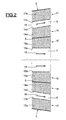
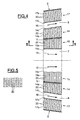
- the absorbent coating 14, 15 and 17 are constituted by panels 14a, 15a, 17a having a resonator structure shown here as Helmholtz resonators.
- the cavities or open cells 20 have the shape of hexagonal base cylinders as can be seen in the section of Figure 5, thus forming a honeycomb structure.
- the axis of the cells 20 is, in this example and for illustrative purposes, substantially perpendicular to the direction of the flow.
- this structure is welded to a rigid solid wall such as that of the outer casing 3 or the internal partition 5, thus defining a closed bottom for the different cavities or cells 20.
- On the other side is disposed an acoustically resistive porous wall 14c, 15c or 17c.
- the wall 14c, 15c or 17c generally comprises a relatively thin layer of a material capable of dissipating the energy of sound waves by viscous friction of the gases in the pores of the material.
- At least one of the walls 14c, 15c or 17c can be replaced by a simple perforated plate.
- the absorbent coating 14, 15 or 17 allows, during the flow of the exhaust stream, the creation of a movement of the gases through the pores of the wall 14c, 15c or 17c generating a resistive damping by dissipation of sound energy.
- This damping can be reinforced by judiciously taking a depth for cavities or cells. multiple of a quarter of the wavelength.
- acoustic damping at a determined frequency depending on the depth of the cavities or cells 20.
- the acoustic damping also depends on other parameters such as the temperature of the gases of the flow as well as the speed of the 'flow. It will be understood that the structure of the absorbent coating and in particular the thickness of the acoustic absorption layers 14a, 15a or 17a, i.e. the depth of cavities or cells 20 of the cellular structure illustrated in FIGS. 5, can easily be adapted according to the operating parameters of the turbomachine.
- FIG. 6 illustrates an example of modification of the cellular structure illustrated in FIG. 4, for the absorbent coating 17.
- a double resonator consisting of two superimposed resonators represented here in the form of Helmholtz resonators is used.
- a porous wall 23 is inserted between two layers 21 and 22 and cavities or open cells 20.
- the depth of the cavities or cells of the two layers 21 and 22 is identical, but it would be possible on the contrary to provide depths different.
- the double Helmholtz resonator is associated, on the flow side, with an acoustically resistive porous wall 17c identical to that of the previous embodiment.
- the porous walls 17c and 23 may be identical and constitute the resistive walls of the two resonators.
- the sound waves then penetrate into the first resonator comprising the porous wall 17c and the cavities of the layer 22, then into the second resonator comprising the porous wall 23 and the cavities of the layer 21.
- the wall 23 may be simply constituted of a porous material acoustically little or not resistive.
- the wall 23 may also consist of a simple perforated sheet.
- Such a dual resonator absorbent coating of Helmholtz has the advantage of extending the frequency tuning over a wider band than in the case of a single row of resonators.
- FIG. 7 schematically illustrates the case of an escapement 1 comprising a central body 24 extending essentially over the entire length of the exhaust 1.
- central body has the side of the inlet 4 a conical shape 24a whose section decreases in the direction of flow.
- a separation of substantially conical shape 5 and then cylindrical is mounted inside the escapement 1 between the central body 24 and the outer wall 3.
- Two substantially annular and concentric flow channels 25 and 26 are thus defined in FIG. interior of the exhaust 1 whose general shape is first conical and then approximately cylindrical.
- An acoustically absorbing coating is provided on all internal surfaces of the exhaust 1, in contact with the gas flow stream.
- This coating may be identical to that described with reference to any one of the preceding embodiments.
- a coating 17 is provided inside the outer wall 3.
- an acoustically absorbing coating 14, 15 is provided on each side of the solid wall of the internal partition 5.
- a coating acoustically absorbing 27 is provided all around the central body 24.
- the multichannel turbomachine exhaust according to the present invention is thus treated acoustically and whatever its geometry, the inlet being generally symmetrical with respect to the axis of the flow, the concentric flow channels being able to evolve into a shape any output, either in the motor axis, or outside this axis thus exerting a jet deflection function.
- the separation provided inside the exhaust device delimiting the flow channels may comprise an acoustically absorbing coating of progressive or uniform thickness depending on the acoustic characteristics that it is desired to obtain.
- the vein heights of the different flow channels can be optimized so that the flow rates in each channel are adapted to the acoustically treated surface and that the acoustic performance is the best possible.
- the outer shell as the internal separation have been provided with an acoustically absorbing coating
- the invention also applies to the case where only the internal separation would be provided with such an acoustically coating absorbent.
- the invention would also apply under the same conditions to a structure in which the internal separation would not be coated with an acoustically absorbing coating, but where this coating would be provided only within the outer casing of the exhaust.
- the acoustically absorbent coatings have been of the same structure in a specific embodiment, it will be understood that it would be possible to obtain different characteristics, to provide in the same exhaust different structures of acoustically absorbing coating in different locations, so as to meet specific acoustic treatment conditions.
- the acoustic treatment surface can be considerably increased by keeping the same size and aerodynamic performance equal or greater. It is also possible to improve the compactness of the assembly by producing a shorter length exhaust while maintaining an optimal acoustic treatment surface.
Landscapes
- Engineering & Computer Science (AREA)
- Chemical & Material Sciences (AREA)
- Combustion & Propulsion (AREA)
- Mechanical Engineering (AREA)
- General Engineering & Computer Science (AREA)
- Exhaust Silencers (AREA)
- Structures Of Non-Positive Displacement Pumps (AREA)
- Input Circuits Of Receivers And Coupling Of Receivers And Audio Equipment (AREA)
- Physical Or Chemical Processes And Apparatus (AREA)
Applications Claiming Priority (2)
| Application Number | Priority Date | Filing Date | Title |
|---|---|---|---|
| FR9815942A FR2787513B1 (fr) | 1998-12-17 | 1998-12-17 | Dispositif d'echappement multicanal de turbomachine traite acoustiquement |
| FR9815942 | 1998-12-17 |
Publications (2)
| Publication Number | Publication Date |
|---|---|
| EP1010884A1 EP1010884A1 (fr) | 2000-06-21 |
| EP1010884B1 true EP1010884B1 (fr) | 2006-07-19 |
Family
ID=9534084
Family Applications (1)
| Application Number | Title | Priority Date | Filing Date |
|---|---|---|---|
| EP99403129A Expired - Lifetime EP1010884B1 (fr) | 1998-12-17 | 1999-12-14 | Dispositif d'échappement multicanal de turbomachine traité acoustiquement |
Country Status (10)
| Country | Link |
|---|---|
| US (1) | US6672424B2 (da) |
| EP (1) | EP1010884B1 (da) |
| AT (1) | ATE333583T1 (da) |
| CA (1) | CA2292821C (da) |
| CY (1) | CY1105644T1 (da) |
| DE (1) | DE69932394T2 (da) |
| DK (1) | DK1010884T3 (da) |
| ES (1) | ES2268838T3 (da) |
| FR (1) | FR2787513B1 (da) |
| PT (1) | PT1010884E (da) |
Families Citing this family (27)
| Publication number | Priority date | Publication date | Assignee | Title |
|---|---|---|---|---|
| US6615576B2 (en) * | 2001-03-29 | 2003-09-09 | Honeywell International Inc. | Tortuous path quiet exhaust eductor system |
| US7028416B1 (en) * | 2003-04-21 | 2006-04-18 | Darryl D Dobie | Noise attenuating drying apparatus for motor vehicles |
| US7121814B2 (en) * | 2004-09-30 | 2006-10-17 | Carrier Corporation | Compressor sound suppression |
| EP1805417A4 (en) | 2004-10-20 | 2010-10-06 | Carrier Corp | REMOVING NOISE FROM A COMPRESSOR |
| US7367424B2 (en) * | 2005-02-14 | 2008-05-06 | Honeywell International, Inc. | Eccentric exhaust muffler for use with auxiliary power units |
| FR2885955B1 (fr) * | 2005-05-18 | 2007-06-22 | Airbus France Sas | Procede pour reduire les emissions sonores a l'arriere d'un turbomoteur et turbomoteur ainsi perfectionne. |
| EP1732062B1 (de) * | 2005-06-07 | 2013-08-14 | Alstom Technology Ltd | Schalldämpfer |
| WO2007017317A1 (de) * | 2005-08-08 | 2007-02-15 | Alstom Technology Ltd | Schalldämpfer für gasturbinenanlagen |
| US7472774B1 (en) * | 2006-01-27 | 2009-01-06 | Lockheed Martin Corporation | Versatile engine muffling system |
| FR2905984B1 (fr) * | 2006-09-20 | 2011-12-30 | Turbomeca | Moteur d'helicoptere a turbine a gaz a emission sonore reduite par traitement acoustique d'un ejecteur |
| US7762374B2 (en) * | 2006-11-22 | 2010-07-27 | Honeywell International Inc. | Turbine engine diffusing exhaust muffler |
| FR2941495B1 (fr) | 2009-01-27 | 2017-09-29 | Turbomeca | Conduit d'echappement insonorise pour turbomoteur |
| FR2946090B1 (fr) * | 2009-05-27 | 2016-01-22 | Turbomeca | Turbomoteur comportant un cone de guidage des gaz d'echappement avec un attenuateur sonore. |
| US9200537B2 (en) | 2011-11-09 | 2015-12-01 | Pratt & Whitney Canada Corp. | Gas turbine exhaust case with acoustic panels |
| US9416752B2 (en) | 2012-02-28 | 2016-08-16 | Pratt & Whitney Canada Corp. | Gas turbine exhaust having reduced jet noise |
| US9309842B2 (en) * | 2013-02-07 | 2016-04-12 | General Electric Company | Air inlet silencer for turbomachines |
| US9631542B2 (en) * | 2013-06-28 | 2017-04-25 | General Electric Company | System and method for exhausting combustion gases from gas turbine engines |
| US20150059312A1 (en) * | 2013-08-29 | 2015-03-05 | General Electric Company | Exhaust stack having a co-axial silencer |
| US9969500B2 (en) | 2014-02-06 | 2018-05-15 | Honeywell International Inc. | Bifurcated ducts including plenums for stabilizing flow therethrough and exhaust systems including the same |
| US11655816B2 (en) * | 2015-05-08 | 2023-05-23 | Danfoss Power Solutions Gmbh & Co. Ohg | Fluid working systems |
| US9587563B2 (en) * | 2015-07-21 | 2017-03-07 | The Boeing Company | Sound attenuation apparatus and method |
| US9771868B2 (en) | 2015-07-21 | 2017-09-26 | The Boeing Company | Sound attenuation apparatus and method |
| US10533452B2 (en) * | 2017-07-19 | 2020-01-14 | Garrett Transportation I Inc. | Acoustic damper with barrier member configured to dampen acoustic energy propogating upstream in gas flow |
| DE102018212802A1 (de) * | 2018-08-01 | 2020-02-06 | Brose Fahrzeugteile GmbH & Co. Kommanditgesellschaft, Würzburg | Verdichtermodul und Kältemittelverdichter mit einem solchen Verdichtermodul |
| CN112901292B (zh) * | 2021-03-30 | 2025-12-09 | 烟台杰瑞石油装备技术有限公司 | 排气装置及其安装方法、涡轮压裂设备 |
| CN114215707B (zh) * | 2021-12-31 | 2024-04-19 | 北京金风科创风电设备有限公司 | 消声装置和风力发电机组 |
| US12415611B2 (en) * | 2023-06-26 | 2025-09-16 | Pratt & Whitney Canada Corp. | Turbo-compounded engine with exhaust duct acoustic arrangement |
Family Cites Families (19)
| Publication number | Priority date | Publication date | Assignee | Title |
|---|---|---|---|---|
| US2869671A (en) * | 1953-08-31 | 1959-01-20 | Karl E Schlachter | Gas turbine muffler |
| US2886121A (en) * | 1956-10-25 | 1959-05-12 | John T Welbourn | Air-cooled silencer |
| US3033307A (en) * | 1959-10-06 | 1962-05-08 | Industrial Acoustics Co | Noise attenuating apparatus |
| FR1580553A (da) * | 1968-07-26 | 1969-09-05 | ||
| US3511336A (en) * | 1969-06-10 | 1970-05-12 | Rink Corp | Sound attenuator for air flow |
| US3602333A (en) * | 1969-10-15 | 1971-08-31 | Chiyoda Chem Eng Construct Co | Silencer for suction or discharge of fluids under pressure |
| US3721389A (en) * | 1971-06-10 | 1973-03-20 | Boeing Co | Exit nozzle assemblies for gas turbine power plants |
| FR2191025B1 (da) * | 1972-07-04 | 1975-03-07 | Aerospatiale | |
| US3831376A (en) * | 1973-02-05 | 1974-08-27 | Boeing Co | Thrust reverser |
| US3890060A (en) * | 1974-02-15 | 1975-06-17 | Gen Electric | Acoustic duct with asymmetric acoustical treatment |
| GB1522558A (en) * | 1976-04-05 | 1978-08-23 | Rolls Royce | Duct linings |
| US4109750A (en) * | 1977-05-24 | 1978-08-29 | Lockheed Aircraft Corporation | Zeno duct sound attenuating means |
| US4244441A (en) * | 1979-07-31 | 1981-01-13 | The Garrett Corporation | Broad band acoustic attenuator |
| DE3401210A1 (de) * | 1984-01-14 | 1985-07-25 | ASEA AB, Västerås | Schalldaempfer zum anschluss an einen stroemungskanal |
| GB8910971D0 (en) * | 1989-05-12 | 1989-06-28 | Sound Attenuators Ltd | Improvements in attenuators |
| JP2630652B2 (ja) * | 1989-08-09 | 1997-07-16 | 三菱電機ホーム機器株式会社 | 送風機 |
| US4953659A (en) * | 1989-08-25 | 1990-09-04 | Norris Thomas R | Fluid blow-off muffler |
| US5777947A (en) * | 1995-03-27 | 1998-07-07 | Georgia Tech Research Corporation | Apparatuses and methods for sound absorption using hollow beads loosely contained in an enclosure |
| DE19803161C2 (de) * | 1998-01-28 | 2000-03-16 | Alstom Energy Syst Gmbh | Gasturbinenschalldämpfer mit Diffusor |
-
1998
- 1998-12-17 FR FR9815942A patent/FR2787513B1/fr not_active Expired - Fee Related
-
1999
- 1999-12-14 AT AT99403129T patent/ATE333583T1/de active
- 1999-12-14 PT PT99403129T patent/PT1010884E/pt unknown
- 1999-12-14 ES ES99403129T patent/ES2268838T3/es not_active Expired - Lifetime
- 1999-12-14 EP EP99403129A patent/EP1010884B1/fr not_active Expired - Lifetime
- 1999-12-14 DK DK99403129T patent/DK1010884T3/da active
- 1999-12-14 DE DE69932394T patent/DE69932394T2/de not_active Expired - Lifetime
- 1999-12-15 US US09/461,330 patent/US6672424B2/en not_active Expired - Fee Related
- 1999-12-17 CA CA002292821A patent/CA2292821C/fr not_active Expired - Fee Related
-
2006
- 2006-10-04 CY CY20061101427T patent/CY1105644T1/el unknown
Also Published As
| Publication number | Publication date |
|---|---|
| CA2292821A1 (fr) | 2000-06-17 |
| CA2292821C (fr) | 2008-03-18 |
| PT1010884E (pt) | 2006-12-29 |
| DE69932394T2 (de) | 2007-07-12 |
| FR2787513A1 (fr) | 2000-06-23 |
| US20020166718A1 (en) | 2002-11-14 |
| ES2268838T3 (es) | 2007-03-16 |
| ATE333583T1 (de) | 2006-08-15 |
| CY1105644T1 (el) | 2010-12-22 |
| DE69932394D1 (de) | 2006-08-31 |
| EP1010884A1 (fr) | 2000-06-21 |
| US6672424B2 (en) | 2004-01-06 |
| DK1010884T3 (da) | 2006-11-20 |
| FR2787513B1 (fr) | 2001-01-19 |
Similar Documents
| Publication | Publication Date | Title |
|---|---|---|
| EP1010884B1 (fr) | Dispositif d'échappement multicanal de turbomachine traité acoustiquement | |
| EP3850616B1 (fr) | Panneau de traitement acoustique pour turboréacteur | |
| EP3963192B1 (fr) | Intégration d'un amortisseur de flottement du fan dans un carter moteur | |
| EP1843032B1 (fr) | Corps central de tuyère de turboréacteur | |
| EP4264594B1 (fr) | Panneau de traitement acoustique à encombrement réduit pour turboréacteur | |
| EP3779961A1 (fr) | Elément acoustique à double enceinte et encombrement réduit, en particulier pour panneau acoustique d'aéronef | |
| WO2017021628A1 (fr) | Structure d'atténuation acoustique à multiples degrés d'atténuation pour ensemble propulsif d'aéronef | |
| EP3489487A1 (fr) | Panneau d'atténuation acoustique pour aéronef | |
| CA2685287A1 (fr) | Panneau acoustique a caracteristique acoustique variable | |
| EP3963199B1 (fr) | Grille d'inverseur de poussée incluant un traitement acoustique | |
| EP3718759B1 (fr) | Assemblage constituant un materiau acoustiquement absorbant | |
| FR3055662A1 (fr) | Structure interne d'un conduit d'ejection primaire d'une turbomachine comprenant une structure absorbante de sons basses frequences | |
| EP3395675A1 (fr) | Panneau pour le traitement acoustique comprenant une structure acoustiquement resistive poreuse comportant des canaux de connexion | |
| CA3134310A1 (fr) | Grille d'inverseur de poussee incluant un traitement acoustique | |
| WO2018020174A1 (fr) | Panneau d'atténuation acoustique pour ensemble propulsif d'aéronef et ensemble propulsif comportant un tel panneau | |
| EP3395676A1 (fr) | Panneau pour le traitement acoustique comprenant des alveoles contenant chacune une pluralite de conduits | |
| CA3135599A1 (fr) | Grille d'inverseur de poussee incluant un traitement acoustique | |
| WO2009115700A1 (fr) | Panneau acoustique d'une nacelle d'un aerone | |
| CA2869623A1 (fr) | Panneau mince d'absorption d'ondes acoustiques emises par un turboreacteur de nacelle d'aeronef, et nacelle equipee d'un tel panneau | |
| CA2761601C (fr) | Turbomoteur comportant un cone de guidage des gaz d'echappement avec un attenuateur sonore | |
| FR2927952A1 (fr) | Paroi insonorisante, en particulier pour nacelle de turboreacteur | |
| FR2998267A1 (fr) | Nacelle pour turboreacteur | |
| WO2020058651A1 (fr) | Gestion acoustique, sur une turbomachine ou une nacelle | |
| FR3086337A1 (fr) | Gestion acoustique, sur une turbomachine ou une nacelle | |
| FR3078106A1 (fr) | Nacelle de turbomachine comprenant une conduite d'evacuation acoustique |
Legal Events
| Date | Code | Title | Description |
|---|---|---|---|
| PUAI | Public reference made under article 153(3) epc to a published international application that has entered the european phase |
Free format text: ORIGINAL CODE: 0009012 |
|
| AK | Designated contracting states |
Kind code of ref document: A1 Designated state(s): AT BE CH CY DE DK ES FI FR GB GR IE IT LI LU MC NL PT SE |
|
| AX | Request for extension of the european patent |
Free format text: AL;LT;LV;MK;RO;SI |
|
| 17P | Request for examination filed |
Effective date: 20001030 |
|
| AKX | Designation fees paid |
Free format text: AT BE CH CY DE DK ES FI FR GB GR IE IT LI LU MC NL PT SE |
|
| 17Q | First examination report despatched |
Effective date: 20040329 |
|
| GRAP | Despatch of communication of intention to grant a patent |
Free format text: ORIGINAL CODE: EPIDOSNIGR1 |
|
| GRAS | Grant fee paid |
Free format text: ORIGINAL CODE: EPIDOSNIGR3 |
|
| GRAA | (expected) grant |
Free format text: ORIGINAL CODE: 0009210 |
|
| AK | Designated contracting states |
Kind code of ref document: B1 Designated state(s): AT BE CH CY DE DK ES FI FR GB GR IE IT LI LU MC NL PT SE |
|
| REG | Reference to a national code |
Ref country code: GB Ref legal event code: FG4D Free format text: NOT ENGLISH |
|
| REG | Reference to a national code |
Ref country code: CH Ref legal event code: EP |
|
| REG | Reference to a national code |
Ref country code: IE Ref legal event code: FG4D Free format text: LANGUAGE OF EP DOCUMENT: FRENCH |
|
| REF | Corresponds to: |
Ref document number: 69932394 Country of ref document: DE Date of ref document: 20060831 Kind code of ref document: P |
|
| REG | Reference to a national code |
Ref country code: SE Ref legal event code: TRGR |
|
| GBT | Gb: translation of ep patent filed (gb section 77(6)(a)/1977) |
Effective date: 20061025 |
|
| REG | Reference to a national code |
Ref country code: DK Ref legal event code: T3 |
|
| REG | Reference to a national code |
Ref country code: GR Ref legal event code: EP Ref document number: 20060403438 Country of ref document: GR |
|
| REG | Reference to a national code |
Ref country code: PT Ref legal event code: SC4A Free format text: AVAILABILITY OF NATIONAL TRANSLATION Effective date: 20061016 |
|
| REG | Reference to a national code |
Ref country code: ES Ref legal event code: FG2A Ref document number: 2268838 Country of ref document: ES Kind code of ref document: T3 |
|
| PLBE | No opposition filed within time limit |
Free format text: ORIGINAL CODE: 0009261 |
|
| STAA | Information on the status of an ep patent application or granted ep patent |
Free format text: STATUS: NO OPPOSITION FILED WITHIN TIME LIMIT |
|
| 26N | No opposition filed |
Effective date: 20070420 |
|
| PGFP | Annual fee paid to national office [announced via postgrant information from national office to epo] |
Ref country code: NL Payment date: 20101124 Year of fee payment: 12 Ref country code: MC Payment date: 20101124 Year of fee payment: 12 Ref country code: IE Payment date: 20101124 Year of fee payment: 12 Ref country code: FR Payment date: 20101203 Year of fee payment: 12 Ref country code: DK Payment date: 20101124 Year of fee payment: 12 Ref country code: AT Payment date: 20101125 Year of fee payment: 12 |
|
| PGFP | Annual fee paid to national office [announced via postgrant information from national office to epo] |
Ref country code: PT Payment date: 20101206 Year of fee payment: 12 Ref country code: LU Payment date: 20101129 Year of fee payment: 12 Ref country code: FI Payment date: 20101125 Year of fee payment: 12 Ref country code: CH Payment date: 20101126 Year of fee payment: 12 |
|
| PGFP | Annual fee paid to national office [announced via postgrant information from national office to epo] |
Ref country code: BE Payment date: 20101126 Year of fee payment: 12 Ref country code: GR Payment date: 20101125 Year of fee payment: 12 Ref country code: SE Payment date: 20101126 Year of fee payment: 12 Ref country code: IT Payment date: 20101127 Year of fee payment: 12 Ref country code: GB Payment date: 20101201 Year of fee payment: 12 |
|
| PGFP | Annual fee paid to national office [announced via postgrant information from national office to epo] |
Ref country code: DE Payment date: 20101208 Year of fee payment: 12 |
|
| PGFP | Annual fee paid to national office [announced via postgrant information from national office to epo] |
Ref country code: ES Payment date: 20101210 Year of fee payment: 12 |
|
| PGFP | Annual fee paid to national office [announced via postgrant information from national office to epo] |
Ref country code: CY Payment date: 20101123 Year of fee payment: 12 |
|
| REG | Reference to a national code |
Ref country code: PT Ref legal event code: MM4A Free format text: LAPSE DUE TO NON-PAYMENT OF FEES Effective date: 20120614 |
|
| BERE | Be: lapsed |
Owner name: TURBOMECA Effective date: 20111231 |
|
| REG | Reference to a national code |
Ref country code: NL Ref legal event code: V1 Effective date: 20120701 |
|
| REG | Reference to a national code |
Ref country code: DK Ref legal event code: EBP |
|
| PG25 | Lapsed in a contracting state [announced via postgrant information from national office to epo] |
Ref country code: MC Free format text: LAPSE BECAUSE OF NON-PAYMENT OF DUE FEES Effective date: 20111231 |
|
| REG | Reference to a national code |
Ref country code: CH Ref legal event code: PL Ref country code: SE Ref legal event code: EUG |
|
| GBPC | Gb: european patent ceased through non-payment of renewal fee |
Effective date: 20111214 |
|
| PG25 | Lapsed in a contracting state [announced via postgrant information from national office to epo] |
Ref country code: PT Free format text: LAPSE BECAUSE OF NON-PAYMENT OF DUE FEES Effective date: 20120614 Ref country code: FI Free format text: LAPSE BECAUSE OF NON-PAYMENT OF DUE FEES Effective date: 20111214 |
|
| REG | Reference to a national code |
Ref country code: GR Ref legal event code: ML Ref document number: 20060403438 Country of ref document: GR Effective date: 20120704 |
|
| REG | Reference to a national code |
Ref country code: FR Ref legal event code: ST Effective date: 20120831 |
|
| REG | Reference to a national code |
Ref country code: IE Ref legal event code: MM4A |
|
| PG25 | Lapsed in a contracting state [announced via postgrant information from national office to epo] |
Ref country code: CY Free format text: LAPSE BECAUSE OF NON-PAYMENT OF DUE FEES Effective date: 20111214 |
|
| REG | Reference to a national code |
Ref country code: DE Ref legal event code: R119 Ref document number: 69932394 Country of ref document: DE Effective date: 20120703 |
|
| PG25 | Lapsed in a contracting state [announced via postgrant information from national office to epo] |
Ref country code: IE Free format text: LAPSE BECAUSE OF NON-PAYMENT OF DUE FEES Effective date: 20111214 Ref country code: BE Free format text: LAPSE BECAUSE OF NON-PAYMENT OF DUE FEES Effective date: 20111231 Ref country code: GB Free format text: LAPSE BECAUSE OF NON-PAYMENT OF DUE FEES Effective date: 20111214 Ref country code: SE Free format text: LAPSE BECAUSE OF NON-PAYMENT OF DUE FEES Effective date: 20111215 Ref country code: CH Free format text: LAPSE BECAUSE OF NON-PAYMENT OF DUE FEES Effective date: 20111231 Ref country code: LI Free format text: LAPSE BECAUSE OF NON-PAYMENT OF DUE FEES Effective date: 20111231 Ref country code: DE Free format text: LAPSE BECAUSE OF NON-PAYMENT OF DUE FEES Effective date: 20120703 |
|
| PG25 | Lapsed in a contracting state [announced via postgrant information from national office to epo] |
Ref country code: GR Free format text: LAPSE BECAUSE OF NON-PAYMENT OF DUE FEES Effective date: 20120704 Ref country code: IT Free format text: LAPSE BECAUSE OF NON-PAYMENT OF DUE FEES Effective date: 20111214 |
|
| REG | Reference to a national code |
Ref country code: AT Ref legal event code: MM01 Ref document number: 333583 Country of ref document: AT Kind code of ref document: T Effective date: 20111214 |
|
| PG25 | Lapsed in a contracting state [announced via postgrant information from national office to epo] |
Ref country code: AT Free format text: LAPSE BECAUSE OF NON-PAYMENT OF DUE FEES Effective date: 20111214 Ref country code: NL Free format text: LAPSE BECAUSE OF NON-PAYMENT OF DUE FEES Effective date: 20120701 Ref country code: DK Free format text: LAPSE BECAUSE OF NON-PAYMENT OF DUE FEES Effective date: 20120102 |
|
| PG25 | Lapsed in a contracting state [announced via postgrant information from national office to epo] |
Ref country code: FR Free format text: LAPSE BECAUSE OF NON-PAYMENT OF DUE FEES Effective date: 20120102 |
|
| PG25 | Lapsed in a contracting state [announced via postgrant information from national office to epo] |
Ref country code: LU Free format text: LAPSE BECAUSE OF NON-PAYMENT OF DUE FEES Effective date: 20111214 |
|
| REG | Reference to a national code |
Ref country code: ES Ref legal event code: FD2A Effective date: 20130703 |
|
| PG25 | Lapsed in a contracting state [announced via postgrant information from national office to epo] |
Ref country code: ES Free format text: LAPSE BECAUSE OF NON-PAYMENT OF DUE FEES Effective date: 20111215 |