EP1010908A2 - Dispositif de guidage linéaire - Google Patents
Dispositif de guidage linéaire Download PDFInfo
- Publication number
- EP1010908A2 EP1010908A2 EP99124583A EP99124583A EP1010908A2 EP 1010908 A2 EP1010908 A2 EP 1010908A2 EP 99124583 A EP99124583 A EP 99124583A EP 99124583 A EP99124583 A EP 99124583A EP 1010908 A2 EP1010908 A2 EP 1010908A2
- Authority
- EP
- European Patent Office
- Prior art keywords
- guide device
- linear guide
- cover
- guide rail
- rotor assembly
- Prior art date
- Legal status (The legal status is an assumption and is not a legal conclusion. Google has not performed a legal analysis and makes no representation as to the accuracy of the status listed.)
- Granted
Links
- 230000000873 masking effect Effects 0.000 claims abstract description 110
- 239000000463 material Substances 0.000 claims abstract description 15
- 239000000314 lubricant Substances 0.000 claims description 26
- 230000001050 lubricating effect Effects 0.000 claims description 21
- 239000004033 plastic Substances 0.000 claims description 8
- 229910000831 Steel Inorganic materials 0.000 claims description 6
- 238000004873 anchoring Methods 0.000 claims description 6
- 239000010959 steel Substances 0.000 claims description 6
- 238000013459 approach Methods 0.000 claims description 5
- 238000005461 lubrication Methods 0.000 claims description 5
- 230000001681 protective effect Effects 0.000 claims description 5
- 238000003860 storage Methods 0.000 claims description 5
- 239000007769 metal material Substances 0.000 claims description 3
- 238000011109 contamination Methods 0.000 abstract description 4
- 238000007789 sealing Methods 0.000 description 7
- 239000000243 solution Substances 0.000 description 6
- 239000000356 contaminant Substances 0.000 description 5
- 238000013461 design Methods 0.000 description 4
- 210000002414 leg Anatomy 0.000 description 4
- 230000007246 mechanism Effects 0.000 description 4
- 239000000203 mixture Substances 0.000 description 4
- 238000012986 modification Methods 0.000 description 4
- 230000004048 modification Effects 0.000 description 4
- 210000002445 nipple Anatomy 0.000 description 4
- 238000000576 coating method Methods 0.000 description 3
- 230000000694 effects Effects 0.000 description 3
- 239000004519 grease Substances 0.000 description 3
- 239000002184 metal Substances 0.000 description 3
- 229910052751 metal Inorganic materials 0.000 description 3
- 239000002245 particle Substances 0.000 description 3
- 230000035515 penetration Effects 0.000 description 3
- 238000003825 pressing Methods 0.000 description 3
- 238000005096 rolling process Methods 0.000 description 3
- 230000000712 assembly Effects 0.000 description 2
- 238000000429 assembly Methods 0.000 description 2
- 239000011248 coating agent Substances 0.000 description 2
- 230000006735 deficit Effects 0.000 description 2
- 238000005538 encapsulation Methods 0.000 description 2
- 238000009434 installation Methods 0.000 description 2
- 238000000034 method Methods 0.000 description 2
- 239000003921 oil Substances 0.000 description 2
- 229920000642 polymer Polymers 0.000 description 2
- 230000008569 process Effects 0.000 description 2
- TVEXGJYMHHTVKP-UHFFFAOYSA-N 6-oxabicyclo[3.2.1]oct-3-en-7-one Chemical compound C1C2C(=O)OC1C=CC2 TVEXGJYMHHTVKP-UHFFFAOYSA-N 0.000 description 1
- 229910001229 Pot metal Inorganic materials 0.000 description 1
- 229910000639 Spring steel Inorganic materials 0.000 description 1
- 230000002745 absorbent Effects 0.000 description 1
- 239000002250 absorbent Substances 0.000 description 1
- 230000009471 action Effects 0.000 description 1
- 230000001154 acute effect Effects 0.000 description 1
- 230000008859 change Effects 0.000 description 1
- 238000010073 coating (rubber) Methods 0.000 description 1
- 239000002131 composite material Substances 0.000 description 1
- 230000001419 dependent effect Effects 0.000 description 1
- 238000006073 displacement reaction Methods 0.000 description 1
- 239000000428 dust Substances 0.000 description 1
- 238000005516 engineering process Methods 0.000 description 1
- 239000006260 foam Substances 0.000 description 1
- 239000012535 impurity Substances 0.000 description 1
- 230000001939 inductive effect Effects 0.000 description 1
- 238000002347 injection Methods 0.000 description 1
- 239000007924 injection Substances 0.000 description 1
- 238000003780 insertion Methods 0.000 description 1
- 230000037431 insertion Effects 0.000 description 1
- 239000010687 lubricating oil Substances 0.000 description 1
- 238000003754 machining Methods 0.000 description 1
- 230000005415 magnetization Effects 0.000 description 1
- 238000004519 manufacturing process Methods 0.000 description 1
- 230000036316 preload Effects 0.000 description 1
- 230000002028 premature Effects 0.000 description 1
- 238000005057 refrigeration Methods 0.000 description 1
- 239000004753 textile Substances 0.000 description 1
- 238000012546 transfer Methods 0.000 description 1
- 210000000689 upper leg Anatomy 0.000 description 1
- 238000004804 winding Methods 0.000 description 1
Images





Classifications
-
- F—MECHANICAL ENGINEERING; LIGHTING; HEATING; WEAPONS; BLASTING
- F16—ENGINEERING ELEMENTS AND UNITS; GENERAL MEASURES FOR PRODUCING AND MAINTAINING EFFECTIVE FUNCTIONING OF MACHINES OR INSTALLATIONS; THERMAL INSULATION IN GENERAL
- F16C—SHAFTS; FLEXIBLE SHAFTS; ELEMENTS OR CRANKSHAFT MECHANISMS; ROTARY BODIES OTHER THAN GEARING ELEMENTS; BEARINGS
- F16C29/00—Bearings for parts moving only linearly
- F16C29/08—Arrangements for covering or protecting the ways
- F16C29/082—Arrangements for covering or protecting the ways fixed to the way
-
- F—MECHANICAL ENGINEERING; LIGHTING; HEATING; WEAPONS; BLASTING
- F16—ENGINEERING ELEMENTS AND UNITS; GENERAL MEASURES FOR PRODUCING AND MAINTAINING EFFECTIVE FUNCTIONING OF MACHINES OR INSTALLATIONS; THERMAL INSULATION IN GENERAL
- F16C—SHAFTS; FLEXIBLE SHAFTS; ELEMENTS OR CRANKSHAFT MECHANISMS; ROTARY BODIES OTHER THAN GEARING ELEMENTS; BEARINGS
- F16C29/00—Bearings for parts moving only linearly
- F16C29/04—Ball or roller bearings
- F16C29/06—Ball or roller bearings in which the rolling bodies circulate partly without carrying load
- F16C29/0633—Ball or roller bearings in which the rolling bodies circulate partly without carrying load with a bearing body defining a U-shaped carriage, i.e. surrounding a guide rail or track on three sides
- F16C29/0635—Ball or roller bearings in which the rolling bodies circulate partly without carrying load with a bearing body defining a U-shaped carriage, i.e. surrounding a guide rail or track on three sides whereby the return paths are provided as bores in a main body of the U-shaped carriage, e.g. the main body of the U-shaped carriage is a single part with end caps provided at each end
- F16C29/0638—Ball or roller bearings in which the rolling bodies circulate partly without carrying load with a bearing body defining a U-shaped carriage, i.e. surrounding a guide rail or track on three sides whereby the return paths are provided as bores in a main body of the U-shaped carriage, e.g. the main body of the U-shaped carriage is a single part with end caps provided at each end with balls
- F16C29/0642—Ball or roller bearings in which the rolling bodies circulate partly without carrying load with a bearing body defining a U-shaped carriage, i.e. surrounding a guide rail or track on three sides whereby the return paths are provided as bores in a main body of the U-shaped carriage, e.g. the main body of the U-shaped carriage is a single part with end caps provided at each end with balls with four rows of balls
- F16C29/0645—Ball or roller bearings in which the rolling bodies circulate partly without carrying load with a bearing body defining a U-shaped carriage, i.e. surrounding a guide rail or track on three sides whereby the return paths are provided as bores in a main body of the U-shaped carriage, e.g. the main body of the U-shaped carriage is a single part with end caps provided at each end with balls with four rows of balls with load directions in O-arrangement
Definitions
- the invention relates to a linear guide device comprising a Guide rail with a longitudinal axis and at least one guide track and one on the at least one guideway in the direction of Longitudinal axis guided rotor assembly.
- Contamination on the guideway can lead to impairments the smoothness and the guiding precision of the rotor assembly and to cause premature wear.
- Such contaminants can from hot shavings originate in machine tools that work accumulate and lie on the guideways, even there is a risk that the chips will burn into the guideways.
- Other contaminants are dirt and dust particles that can can deposit on the guideways.
- an abrasive mixture can be formed which, if it gets into the rotor assembly, wear on the guideways and can guide the guide elements of the rotor assembly.
- conventional rotor assemblies are often all around compared to the Guide rail are sealed, can not be 100 percent Prevent contaminants from entering the inside of the rotor assembly reach. Micro roughness in the guide rail surface and the sealing elements used are often can not be avoided. Through this micro roughness is then Penetration of contaminants inside the rotor assembly possible.
- a covering solution is known from DE 43 34 311 A1, with a guide rail in a U-shaped profile housing on the bottom is attached and the longitudinal opening of the housing through a Masking tape is closed on the opposite one another Side walls of the housing abuts.
- This solution offers a safe one Protection against the ingress of contaminants into the interior of the Housing, but is due to the presence of the U-shaped profile housing bound and therefore only suitable for special applications.
- the object of the invention is therefore one for a wide range of applications to specify a suitable covering solution for the linear guide devices, which provides reliable protection against pollution-related with little effort Impairment of the guide quality of the linear guide device offers.
- the invention provides that the Guideway in the direction of the longitudinal axis on both sides of the rotor assembly essentially over the respective total remaining length a masking tape is covered, which is at least one masking tape contact zone of the guide rail or this cover band contact zone obvious.
- a masking tape is covered, which is at least one masking tape contact zone of the guide rail or this cover band contact zone obvious.
- Masking tape accordingly directly on the guide rail. If that Masking tape is not physically in contact with the masking tape contact zone, but this is only "obvious", this should mean that the distance between masking tape contact zone and masking tape is small enough to the penetration of those in question in the respective application Prevent particles or other foreign matter. This results in a high degree of independence from the structural installation conditions the linear guide device, regardless of whether this is e.g. with a U housing is executed or without.
- the masking tape as it do not squeeze and pull apart must leave, from a sufficiently insensitive to hot shavings Material are made.
- Telescopic covers result in a significantly reduced design effort the covering solution according to the invention. It also remains essentially the entire travel path received by the guide rail is available because the masking tape does not require storage space that the would restrict the travel of the rotor assembly.
- the masking tape contact zones and the guideway agree at least partially.
- An optimal adjustment of the Masking tape contact zone to the requirements of the masking tape, in particular as far as the tightness of the system is concerned, without the concrete Design of the guideway, can be achieved in that the masking tape contact zone and the Guideway are at least partially different.
- Optimal protection of the guideway results when the masking tape covers the guideway without contact and at right angles to Longitudinal axis of masking tape contact zones on both sides of the guideway the guide rail rests. This can be done simply by be achieved that the guideway in one of the masking tape covered recess of the guide rail is arranged, which is formed between the masking tape contact zones.
- the opposite masking tape contact zones include flat side contact zones where the Masking tape on its flat side facing the guideway is present. It is recommended that the flat side contact zones of flat, coplanar contact surfaces are formed. A flat one this is the tight fit of the masking tape on the guide rail possible.
- At least one masking tape contact zone is designed as a narrow side contact zone, on which the masking tape rests on one of its narrow sides.
- the cover tape can be in its cover position on the guide rail be positively secured, for example in such a way that the Narrow side contact zones for engaging the narrow sides of the masking tape undercuts are formed.
- the masking tape can be used with some play be kept. But it can also on its narrow sides and / or be pinched on its flat sides.
- locking means that are not over the entire length of the Go through the guide rail, but are only trained locally and are distributed over the length of the guide rail.
- the rotor assembly can be equipped with band curvature means in end regions be executed, which the cover tape one of its inlet between opposite narrow side contact zones facilitating Issue constrained curvature and thereby the distance between the Reduce the narrow sides of the masking tape.
- the curling of the masking tape can be helpful to slightly undercut it with its long edges to be able to insert the guide rail. It is possible that the masking tape after insertion into the undercuts completely bent again. If, however, a frictional Clamping the masking tape on its narrow sides is desirable, it is recommended to adjust the width of the masking tape in this way to coordinate the securing means that the cover tape in the cover position has a curvature.
- the securing means can also do so be realized that the masking tape by magnetic means in the cover position is durable.
- the guideway and the cover band contact zone together on a base material-uniform rail body the guide rail are formed the rail body in the area of the guideway and / or the masking tape contact zone subsequent curing or / and coating processes can be subjected, for example, to compensate for the guide rail and improve their resilience.
- the guideway and the masking tape contact zone on the materially integrally connected Rail body may be arranged, although basically it is not excluded that the guideway and the masking tape contact zone on the same basic material but separate rail sections are trained.
- the guide rail not only has a guide track, but also two or more guideways. In this case it is recommended that the guide rail at least two parallel to each other Has guideways that are covered together by the masking tape are.
- the invention is particularly applicable to guide rails that have a Fastening surface, one opposite the fastening surface Head surface and two connecting the fastening surface with the head surface Have side faces, being in each of the side faces at least one guideway is formed and on each side surface at least one masking tape for the associated at least one Guideway is provided. It is particularly convenient if Presence of at least two guideways in each of the Side surfaces all guideways of each of the side surfaces by each a common masking tape are covered.
- the masking tape can be a metallic material, in particular steel, include. It can also include a plastic material. In doing so not be excluded that the masking tape from different Is manufactured, for example with a metallic core that is used for the provides the desired strength, and a plastic sheath or rubber for a good seal between masking tape and Guide rail ensures.
- the invention is basically suitable for all types of management of the Runner assembly on the guide rail. So the rotor assembly be slidably guided on the guideway designed as a slideway. Likewise, the rotor assembly on the roller track Guideway be roller-guided. In the latter case it is possible that the Rotor assembly by at least one roller rotatably mounted on it is guided on the roller track. But it is also possible that the rotor assembly through at least one row along an endless orbit revolving rolling elements is guided on the roller track.
- the masking tape can be moved together on the rotor assembly be attached with this along the longitudinal axis. It can be in the area the rail ends be deflected at deflection means and by one returning tape section to be closed in a loop. Basically two in the area of the rail ends are also conceivable located winding rolls, from which the masking tape unwound or is wound on it, depending on the direction of movement of the rotor assembly.
- the masking tape can even have longitudinal elasticity.
- a preferred embodiment provides that the masking tape is on its flat side facing the guideway grinding over a support surface arrangement the rotor assembly runs away and that the rotor assembly Approach means which the masking tape in Approximate longitudinal direction in front of and behind the support surface arrangement hold against the guide rail.
- the masking tape has free tape ends that at the longitudinally spaced rail ends of the guide rail are held. It is recommended that at least one of the ends of the tape is anchored in an anchoring block, which is attached to a supports the axial end face of the associated rail end, since such a additional machining of the guide rail can be avoided.
- a solution in which the anchoring block is axial facilitates assembly can be plugged onto the associated rail end and at least for this purpose has an axial plug part with which it attaches to the guide rail axially overlaps their outer circumference.
- the masking tape can be tensioned by tensioning means, which in the Area of at least one rail end are arranged.
- tensioning means comprise adjustable clamping components.
- clamping means at least comprise a resilient clamping component.
- a spring preload can with temperature-related changes in length of the masking tape provide for a balance. In addition, it can, if ever stick-slip effects occur between the masking tape and the rotor assembly, Avoid jerky tensile forces on the masking tape.
- the rotor assembly comprises a runner responsible for their leadership on the guide rail, the approach means being attachable to at least one on the rotor Tape guide unit are arranged.
- the runner one can commercially available series component are used to form the Rotor assembly can be taken over essentially without modification can. This applies in particular if the support surface arrangement is also at least in part, in particular completely, on the at least one Tape guide unit is arranged.
- the assembly elements of the runner also serve as fastening elements are designed to attach the tape guide unit. For example can use mounting screws that attach the head units serve the runner on a main body of the runner, with an additional thread be provided which the subsequent attachment of the Belt guide unit on the pre-assembled runner.
- the axially opposite end faces of the Runner each have a tape guide unit attached. These can - at Looking axially away from the rotor - one with increasing Have a slimmer outer contour from the runner, so that there is a pleasing appearance of the rotor assembly.
- the masking tape is expediently guided past the rotor on the outside his. It is then recommended that the masking tape be attached to the at least one tape guide unit attached protective bar Protect damage.
- the rotor assembly can approach means and the support surface arrangement at least one lubricant dispenser for lubrication of the masking tape.
- This lubricant dispenser can include lubricant-containing lubricant, which is in lubricating contact with the masking tape.
- the lubricant can also be in Lubrication contact with at least one covered by the masking tape
- This lubricant is suitably used in a tape guide unit can be arranged, which also in the way can be configured that in it also a lubricant storage chamber is housed, which is in supply connection with the there is at least one lubricating body.
- the lubricant can at least part of the tape guide function of the tape guide unit take.
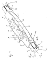
- a rotor assembly 14 is slidably guided.
- the Rotor assembly 14 is curved in the shape of a partial circle in cross section Ball tracks 16 of the guide rail 10 through the mediation of several Ball loops performed.
- the guide rail 10 has a fastening surface 18, with which it is placed on the base, a head surface 20 and two opposite side surfaces 22 in which an approximately trapezoidal groove 24 is formed in each Groove flanks the ball raceways 16 are incorporated. Any side surface 22 of the guide rail 10 thus has two ball raceways 16.
- the linear guide device shown in Fig. 1 is to a longitudinal center plane containing the axis 12 constructed symmetrically.
- each of the ball loops 26 includes a load transfer rectilinear row of balls 28, which is in rolling engagement with one of the guide rail side Ball raceways 16 and with one on the rotor assembly 14 trained supporting ball race 30 is available. Further each ball loop 26 includes a returning straight line of balls 32, which in an associated return channel 34 of the rotor assembly 14 is led.
- the load-transmitting row of balls 28 and the returning Row of balls 32 of each ball loop 26 are at their two ends connected by a row of arches not shown in FIG. 2, which are guided in deflection guides of the rotor assembly 14.
- the rotor assembly 14 engages around the guide rail 10 in a U-shape, with a web area 36 of the head surface 20 of the guide rail 10 is adjacent and each with one of the leg regions 38 Side surfaces 22 of the guide rail 10 is opposite.
- a retaining bar 40 is arranged, which the balls of load-transmitting rows of balls 28 holds on the rotor assembly, so that them when the rotor assembly 14 is removed from the guide rail 10 do not get lost.
- leg regions 38 42 There are also receiving holes in the leg regions 38 42 provided for fastening bolts that the fastening of an object to be moved, such as a table that is placed on different Runner assemblies run over guide rails, or a tool or workpiece holder, on the rotor assembly 14 serve.
- the rotor assembly 14 includes the actual management function accepting runners 44 and two each on one of the axes 12 opposite end faces 46 of the runner 44 attached tape guide units 48, the function of which is explained below.
- the runner 44 is composed of a rotor main body 50, which the return channels 34 for the returning rows of balls 32 contains and on his the inner side of the guide rail 10 facing the rectilinear load-bearing ball raceways 30 for the load-transferring Rows of balls 28 is executed.
- On the two opposite in the axial direction 12 The ends of the rotor main body 50 are each essentially one contoured head unit 52 attached in the at least to Part of the deflection guides for the rows of arches are housed.
- the ball loops 26 and their associated track system are complete housed in the runner 44.
- the tape guide units 48 are for guiding the rotor assembly 14 on the guide rail 10 usually of minor importance. Without major modifications commercially available, pre-assembled runners can be used. It is understood that instead of two ball loops 26 in each leg area 38 of the rotor assembly 14 also only one or three or even even more ball loops 26 can be provided. It does the same no difference in the context of the invention if instead of the balls other rolling elements are used, such as rollers, barrels or Needles.
- bolt receiving holes 54 are provided, which of the Go through the head surface 20 to the fastening surface 18.
- fastening bolts can be used serve to screw the guide rail 10 to the base.
- the cover band 56 lies on the guide rail 10 on the latter entire length against ingress of dirt, with exception the area of the rotor assembly 14 where it is on the outside of the rotor 44 is passed and by the tape guide units 48 on the front and at the rear end of the rotor assembly 14 again on the guide rail 10 is pressed. With a longitudinal movement of the rotor assembly 14 thus grinds along the cover band 56, whereby the term "grinding" in the sense of a low-friction and low-wear Sliding is to be understood.
- FIGS. 3-5 In Fig. 3 the two are on both sides of the guide rail 10 arranged cover strips 56 as metal, especially spring steel strips.
- Each of the masking tapes 56 covers that in the respective side surface 22 of the guide rail 10 trained trapezoidal groove 24 completely and lies with its lateral Longitudinal edges on the flat side on coplanar contact surfaces 58 of the guide rail 10 on. These contact surfaces 58 on which the respective masking tape 56 rests, directly adjoin the ball raceways 16, those in the outermost edge regions of the groove flanks of the trapezoidal groove 24 are arranged.
- the guide rail 10 is made of a metallic Material, especially steel, is made by magnetization the cover strips 56 a secure hold on the guide rail 10 can be achieved.
- the ball raceways 16 can also be covered individually by a masking tape 56.
- a masking tape 56 As well it is understood that in each of the side surfaces 22 of the guide rail 10 more than two ball tracks can be formed, all of them are covered by a common masking tape 56.
- the raceways would be 16 and the contact surfaces 58 on one and the same base material, namely the steel profile. Also an inductive hardening of the Side surface areas of the guide rail 10 would not do anything about this to change.
- the guide rail 10 could also be in the area of the contact surfaces 58 with a coating which increases the sealing effect, for example a rubber coating, be provided without this changes the base material on which the ball raceways 16 and Contact surfaces 58 are formed. After all, shouldn't be excluded either be that the guide rail 10 from several rail part bodies is constructed.
- a head surface masking tape 60 is on the head surface 20 of the guide rail 10 clipped on and grips with side edges bent at an acute angle 62 in each of a recess 64, the near the top surface in each of the Side surfaces 22 is formed.
- the top surface masking tape 60 creates a smooth surface over the into the bolt receiving holes 54 used fastening bolts on which the rotor assembly 14 seals can drive along.
- FIG. 5 shows a masking tape 56 ′′, which is not only on its flat side facing the ball raceway on the guide rail 10 is present, namely in the area of the contact surfaces 58, but also with its narrow sides abuts the guide rail 10.
- the Contact surfaces 58 laterally limited by a shoulder 66 to which the masking tape 56 ′′ abuts with one of its narrow sides.
- the cover band 56 '' against slipping across Guide rail 10 secured.
- the straightening shoulders 66 can be used to frictionally secure the masking tape 56 '' on the guide rail 10 can be used.
- the width the cover band 56 ′′ is somewhat larger than the distance between the two opposite shoulders 66 (of which only one in Fig. 5 to is to be recognized). If the masking tape 56 '' is light on its longitudinal edges is compressed, it bends so that it is between the opposite Straightening shoulders 66 can be inserted. Then it will released, it tends to lie flat again. However, because it is wider than the distance between the opposite ones Straightening shoulders 66, it retains a slight curvature.
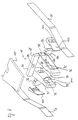
- the one shown there Tape guide unit comprises a tape guide body 68 which is a U-plate part 70 has, the U-legs of the rail side surfaces 22 opposite axial plate extensions 72 go out.
- the Plate extensions 72 can be made in one piece with the plate part 70, approximately as Injection molded part made of plastic. You can also separately be produced by the plate part 70 and with this, for example be connectable by connector means.
- Each of the plate processes 72 has on its inside facing the rail side surface 22 a convex pressure surface 74, which for pressing the Masking tape 56 is used on the guide rail 10.
- Plate part 70 is a passage opening after the pressing surface 74 76 formed in each of the plate extensions 72, which the passage of the masking tape 56 to the outside of the respective side facing away from the rail Plate extension 72 allowed. Finally is on the outside of the thigh each of the plate part 70 also has a slightly convex curvature Lift-off support surface 78 is formed, through which the cover band 56 extends from the The guide rail 10 is lifted off and guided past the runner 44 becomes.
- cover band 56 First be curved before being between opposite ones Straightening shoulders is used, for example, by a suitable shape of the pressing surfaces 74 can be achieved. For this can these with a curvature around a parallel to the tape longitudinal direction Curvature axis are produced, this curvature or convex can be concave.
- the masking tape 56 is thus on the pressure surfaces 74 issued the desired band curvature, which it smoothly between the shoulders 66 of FIG. 5 can enter.
- FIG. 7 shows the course of the guide rail 10 on both sides arranged cover tapes 56 through the tape guide body 68 is granted.
- the masking tapes 56 are each through the lifting support surface 78 lifted out of the system contact with the guide rail 10 and pass the runner 44 at a short distance, so that don't grind on this.
- Fig. 7 you can also see the type of Attachment of the tape guide body 68 to the rotor 44. This is done by means of screw bolts 80 which extend axially through the plate part 70 each screwed into an internal thread that is in the head of a Fastening screw 82 is formed, which in turn serves the To screw head unit 52 to the rotor main body 50.
- screw bolts 80 which extend axially through the plate part 70 each screwed into an internal thread that is in the head of a Fastening screw 82 is formed, which in turn serves the To screw head unit 52 to the rotor main body 50.
- the plate part 70 also has in the middle of its web area Through hole 84 (see Fig. 6) through which a in Runner 44 trained lubricant supply system for supply from whose ball loops with lubricant is accessible from the outside.
- Through hole 84 may include a plug 86 (see FIG. 7) be used.
- a grease nipple can be used. It is also conceivable that in a through hole 84 opposite Lubrication connection bore of the associated head unit 52 such a grease nipple is already inserted and the through hole 84 only allows access to the grease nipple.
- Fig. 2 shows this case, in which the head unit 52 has a Lubricating nipple 88 is executed.
- a lubricating body 96 is housed, on the one hand the masking tape runs away with its flat side facing the rail and on the other hand in lubricating contact with the two ball races 16 of the respective side surface 22 of the guide rail 10 is.
- the Lubrication of the masking tapes 56 reduces their friction-related Wear. It is understood that the masking tapes 56 also on their flat side facing away from the rail by the lubricating body 96 or separate additional lubricants are wetted with lubricant be able to reduce the friction on the pressure surfaces 74.
- the lubricating bodies 96 each protrude from a window 98 of plate extensions 72 to the guide rail 10 and are with Locking recesses 100 held at the window edges. To the masking tapes 56 they protrude through a window 102, which in a cap 104 is formed which is remote from the rail Side can be placed on the respective plate extension 72. Again 7, limit the plate extensions 72 each have an internal cavity 106 with their sealing caps 104, which can be used as a lubricant storage chamber.
- the Lubricating body 96 of absorbent, conductive by capillary action Materials are formed, such as felt or foam when an amount of oil is stored in the cavities 106, the latter with these Cavities 106 associated lubricant 96 independently Provide with oil replenishment so that there is always an even supply of lubricating oil to the cover tapes 56 and the ball tracks 16 guaranteed is.
- the caps 104 can be used to seal the cavities 106 are permanently bonded or welded to the plate extensions 72, in which case those in the lubricating bodies 96 and possibly in the Cavities 106 stored amount of lubricant for life the linear guide device will be matched, unless one additional relubrication connection on the tape guide body 68 is provided.
- the caps 104 of the Plate extensions 72 can be detached, in which case expediently one additional sealing lip arrangement on the closure caps 104 and / or the plate extensions 72 is designed to provide a perfect seal of cavities 106.
- a cover 108 can be placed on the plate extensions 72 from above, which ensures encapsulation of the respective tape guide unit 48.
- On the inside of the plate extensions 72 facing the rail can also an at least approximately the side surface contour of the guide rail 10 reproduced web projection 110 may be formed, which as a coarse wiper for stripping any remaining on the guide rail 10 coarse impurities can serve.
- the web projections 110 in sealing engagement with the side surfaces 22 of the guide rail 10, in particular with the Ball raceways 16 are, so that from the lubricators 96 on the guide rail 10 dispensed lubricant within the rotor assembly 14 remains.
- the tape guide body 68, the caps 104 and the cover 108 made of sprayable Be made of plastic. To protect against hot chips and aggressive Media can also be made of die-cast zinc.
- FIG. 7 the masking tape 56 runs exposed on the outside of the rotor 44 past.
- protective brackets 112 are shown in FIG. 7 shown, which are placed laterally on the rotor assembly 14 and with angled temple ends 114 on the axial end faces of the tape guide units 48 can be snapped into place.
- the Plate extensions 72 locking recesses 116 formed in the corresponding snap pin 118 (see Fig. 7) of the protective bracket 112 intervene.
- the protective bracket 112 cover the masking tapes 56 in Area of the rotor assembly 14 completely.
- Along the runner 44 have a recess 120 on the inside facing the rotor (dashed lines in Fig. 7) in which the respective masking tape 56th running.
- tape guide units 48 slim down with increasing distance from the runner 44, see above that the space required by the tape guide units 48 can be kept low.
- FIG. 8 which essentially shows a section of FIG. 7 one also that the tape guide body 68 on the rotor facing Contact side of the plate part 70, with which the latter on the end face 46 of the rotor 44 comes to rest, one or more positioning rings 122, the positioning of the tape guide body 68 relative serve to the runner 44 and in assigned recesses (not closer shown) which engage in the respective end face 46 of the Runner 14 are formed.
- the positioning rings 122 engage in recesses in the end face 46, in which also the mounting screws 82 used to mount the rotor 44 be used. This can be seen in Fig. 7.
- FIG. 9 shows a variant of FIG. 8 with a different design Lubricant body 96 '. While the masking tape 56 in Fig. 8 essentially runs only over a lubricating edge of the lubricating body 96, the Lubricating body 96 'in Fig. 9 in large-area lubricating contact with the Masking tape 56.
- the material of the lubricating body 96 'a with Lubricant mixed polymer are used, i.e. a material which contains a polymer as the base material, which has lubricating properties during manufacture possessing components were added.
- the Lubricant can be released by pressure or heat Lubricant body 96 'take place.
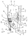
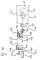
- Fig. 10 shows the attachment of the ends of the masking tape 56 to the Guide rail 10.
- the cover tape 56 is with his Hook end 124 in a hook receptacle 130 of the lower clamping part 126 mounted.
- the clamping upper part 128 by means of screws 132 screwed onto the lower clamping part 126.
- the top clamp engages 128 with a locking projection 134 in the hook receptacle 130 of the lower clamping part 126 and secures the hook end 124 of the Masking tape 56.
- the lower clamping part 126 For assembly, the lower clamping part 126, if necessary together with the screwed clamp top 128, on the guide rail end attached. Is attached here in the sense means that on the lower clamping part 126 axial plug projections 136 are formed, which in the trapezoidal grooves 24 (not shown in Fig. 10) of the both side surfaces 22 of the guide rail 10 preferably form-fitting engage and a rotation of the lower clamping part 126 relative to prevent the guide rail 10 about the longitudinal axis 12.
- the connector tabs 136 do not engage in a press fit, but rather comparatively loosely into the trapezoidal grooves 24 so that the clamping lower part 126 is slidable along the guide rail 10. This movability enables the cover tapes 56 to be tensioned.
- the lower clamp part 126 has on its rail-facing axial side a polygonal recess 138 for form-fitting, that is to say non-rotating Recording a threaded nut 140. Between the Nut 140 and the lower clamping part 126 is inserted into the recess 138 in addition, a bias spring 142 is inserted. An adjustment bolt 144 is then through openings 146 and 148 of the clamping upper part 128 or the lower clamping part 126 screwed into the threaded nut 140, to the extent that it looks out of the threaded nut 140 and with a support end 149 on an axial end face 150 of the guide rail 10 supports.
- 128 fixed masking tapes 56 can be set by one of the Biasing spring 142 applied spring bias is superimposed.
- the this achieved resilient displacement of the terminal block 126.128 is particularly useful for comparatively jerky movements of the rotor assembly 14 advantageous if the rotor assembly at the beginning of the movement 14 tries to pull the masking tapes 56 along.
- the spring 142 enables a balance here.
- the cover tapes 56 can also be spring-loaded be fixed at the rail ends.
- An adjustable voltage setting is useful in that, on the one hand, the assembly of the Clamping mechanism facilitated (the clamping block 126, 128 can initially with tension-free masking tapes 56 on the guide rail 10 can be attached; the belt tension is only through subsequent Screwing in the adjustment bolt 144 applied) and the other retightening the cover tapes 56 is possible, these should slack in some operating time.
- FIG. 11 and 12 are the same or equivalent components in the Fig. 1-10 provided with the same reference numerals, but supplemented by a lowercase letter. For a more detailed explanation, refer to the previous one Description of Figs. 1-10 referenced.
- a rotor assembly 14a is open a guide rail 10a guided longitudinally. Again, this can be a roller guide. Alternatively, the rotor assembly 14a be slidably guided on the guide rail 10.
- a track 16a of the guide rail 10a is covered by a cover band 56a. However, this is not fixed to the rail ends, but to one Loop closed, being rotatable in the area of the rail ends stored deflection rollers 152a and deflected on one of the guideway 16a opposite side of the guide rail 10a returned is.
- the masking tape 56a with the rotor assembly is at fixed points 154a 14a connected. This means that the cover tape 56a at a longitudinal movement of the rotor assembly 14a.
- FIG. 12 there is a cover band 56b with its Longitudinal edges in one each formed on a guide rail 10b, in Cross-section trapezoidal dovetail groove 156b added.
- the dovetail groove 156b is in a groove flank of a rail groove 158b formed undercut, in which one of the masking tape 56b covered guideway 16b.
- masking tape 56b is loose in dovetail groove 156b held. This means that it is neither with its flat sides, nor with its narrow sides is clamped on the guide rail 10b. It lies only on a groove edge serving as a flat side contact zone 58b of the dovetail groove 156b loosely.
- both a flat-sided clamping of the masking tape 56b between the opposite groove edges 58b of the dovetail groove 156b is conceivable, as well as a narrow-sided clamping between the bottom surfaces of two opposite dovetail grooves 156b.
- the cover band 56b suitable curvature imparting means on the tape guide units warp. Provided that the cover band 56b has play on the narrow side in the dovetail groove 156b, it can then be completely restored lay flat.
Landscapes
- Engineering & Computer Science (AREA)
- General Engineering & Computer Science (AREA)
- Mechanical Engineering (AREA)
- Bearings For Parts Moving Linearly (AREA)
Applications Claiming Priority (2)
| Application Number | Priority Date | Filing Date | Title |
|---|---|---|---|
| DE19857028A DE19857028A1 (de) | 1998-12-10 | 1998-12-10 | Linearführungseinrichtung |
| DE19857028 | 1998-12-10 |
Publications (3)
| Publication Number | Publication Date |
|---|---|
| EP1010908A2 true EP1010908A2 (fr) | 2000-06-21 |
| EP1010908A3 EP1010908A3 (fr) | 2003-01-15 |
| EP1010908B1 EP1010908B1 (fr) | 2004-01-28 |
Family
ID=7890640
Family Applications (1)
| Application Number | Title | Priority Date | Filing Date |
|---|---|---|---|
| EP99124583A Expired - Lifetime EP1010908B1 (fr) | 1998-12-10 | 1999-12-09 | Dispositif de guidage linéaire |
Country Status (4)
| Country | Link |
|---|---|
| US (1) | US6435719B1 (fr) |
| EP (1) | EP1010908B1 (fr) |
| JP (1) | JP2000179549A (fr) |
| DE (2) | DE19857028A1 (fr) |
Cited By (3)
| Publication number | Priority date | Publication date | Assignee | Title |
|---|---|---|---|---|
| DE10202737A1 (de) * | 2002-01-24 | 2003-07-31 | Rexroth Star Gmbh | Linearführungseinheit |
| WO2004027276A1 (fr) * | 2002-09-17 | 2004-04-01 | Ina-Schaeffler Kg | Rail de guidage pour un palier lineaire |
| WO2007147821A3 (fr) * | 2006-06-21 | 2008-02-14 | Hettich Paul Gmbh & Co Kg | Glissière pour élément de guidage coulissant |
Families Citing this family (8)
| Publication number | Priority date | Publication date | Assignee | Title |
|---|---|---|---|---|
| JP2005090666A (ja) * | 2003-09-18 | 2005-04-07 | Hama International:Kk | 直動装置およびそのレール保持治具 |
| NO328618B1 (no) * | 2005-08-19 | 2010-04-06 | Niels Bugge | Linear bandforingsinnretning |
| JP2017067077A (ja) * | 2013-12-26 | 2017-04-06 | 日本精工株式会社 | 直動案内軸受装置 |
| CN113021015A (zh) * | 2019-12-25 | 2021-06-25 | 苏州市阳山机械有限公司 | 镶钢导轨的安装定位结构及方法 |
| WO2023286278A1 (fr) * | 2021-07-16 | 2023-01-19 | Dmg森精機株式会社 | Guide de mouvement linéaire et machine-outil |
| US20240093765A1 (en) * | 2022-09-16 | 2024-03-21 | Parker-Hannifin Corporation | Guided strip seal for linear actuator |
| AT527328B1 (de) * | 2023-06-22 | 2025-01-15 | Engel Austria Gmbh | Schließeinheit für eine Formgebungsmaschine |
| TWI841434B (zh) * | 2023-06-29 | 2024-05-01 | 東佑達自動化科技股份有限公司 | 致動器裝置 |
Family Cites Families (22)
| Publication number | Priority date | Publication date | Assignee | Title |
|---|---|---|---|---|
| DE2656622C2 (de) * | 1976-12-14 | 1982-07-01 | Kurt 8000 München Hennig | Energieführungskette zur Aufnahme von Energieführungsleitungen |
| DE3205143C2 (de) * | 1982-02-13 | 1984-02-09 | Reinhard 7310 Plochingen Lipinski | Mechanische Lineareinheit |
| US4481869A (en) * | 1982-05-14 | 1984-11-13 | Greenco Corp. | Fluid operated device with improved sealing means |
| DE3420936C1 (de) * | 1984-06-05 | 1985-12-19 | Kuka Schweissanlagen + Roboter Gmbh, 8900 Augsburg | Schutzvorrichtung fuer die Fuehrungsbahn eines ersten Maschinenteiles,auf dem ein zweites Maschinenteil laengsbeweglich gelagert ist |
| DE8424035U1 (de) * | 1984-08-13 | 1984-11-22 | Herion-Werke Kg, 7012 Fellbach | Kolbenstangenloser zylinder |
| AU579292B2 (en) * | 1985-03-26 | 1988-11-17 | Kuka Schweissanlagen & Roboter Gmbh | Rack drive |
| DE3636138A1 (de) * | 1986-10-24 | 1988-04-28 | Neff Gewindespindeln | Linearlageranordnung |
| DE3804117A1 (de) * | 1988-02-11 | 1989-08-24 | Neff Gewindespindeln | Mechanische lineareinheit |
| FR2659889B1 (fr) * | 1990-03-22 | 1995-05-12 | Coron Jean Paul | Dispositif d'etancheite pour un module lineaire de guidage pour la translation et la manutention de toutes pieces et accessoires. |
| DE4311641C1 (de) | 1993-04-08 | 1994-04-21 | Star Gmbh | Linearbewegungsführung |
| US5415483A (en) * | 1993-08-20 | 1995-05-16 | Tooling Research, Inc. | Sealed linear positioning apparatus |
| DE4334311A1 (de) * | 1993-10-08 | 1995-04-13 | Schaeffler Waelzlager Kg | Schutzabdeckung für eine Laufbahn und eine Vortriebseinrichtung einer Linearführung |
| DE9320135U1 (de) * | 1993-12-23 | 1994-02-17 | Mannesmann AG, 40213 Düsseldorf | Druckmittelbetriebener Arbeitszylinder |
| DE4400453C2 (de) * | 1994-01-11 | 1996-11-07 | Maschimpex Handels & Consulting Ag | Linearantrieb |
| DE19532759B4 (de) | 1995-09-05 | 2004-07-01 | Rexroth Star Gmbh | Linearführungseinheit |
| DE19600737A1 (de) | 1996-01-11 | 1997-07-17 | Alltec Gmbh | Lineargetriebeeinheit |
| DE19605387C2 (de) * | 1996-02-14 | 1998-01-15 | Neff Antriebstech Automation | Führungseinrichtung mit Abdeckband |
| DE19615075A1 (de) | 1996-04-17 | 1997-10-23 | Schaeffler Waelzlager Kg | Führungsschiene für ein Linearlager |
| US5784925A (en) * | 1996-12-13 | 1998-07-28 | Etec Systems, Inc. | Vacuum compatible linear motion device |
| JPH11325070A (ja) * | 1998-05-11 | 1999-11-26 | Nippon Thompson Co Ltd | スライド装置のシール構造 |
| DE19837212A1 (de) * | 1998-08-17 | 2000-02-24 | Itec Ges Fuer Prozesautomation | Stellvorrichtung |
| JP2000230618A (ja) * | 1999-02-10 | 2000-08-22 | Thk Co Ltd | 防塵型案内装置 |
-
1998
- 1998-12-10 DE DE19857028A patent/DE19857028A1/de not_active Ceased
-
1999
- 1999-11-30 US US09/451,998 patent/US6435719B1/en not_active Expired - Fee Related
- 1999-12-09 DE DE59908413T patent/DE59908413D1/de not_active Expired - Lifetime
- 1999-12-09 EP EP99124583A patent/EP1010908B1/fr not_active Expired - Lifetime
- 1999-12-10 JP JP11351917A patent/JP2000179549A/ja active Pending
Cited By (6)
| Publication number | Priority date | Publication date | Assignee | Title |
|---|---|---|---|---|
| DE10202737A1 (de) * | 2002-01-24 | 2003-07-31 | Rexroth Star Gmbh | Linearführungseinheit |
| DE10202737B4 (de) * | 2002-01-24 | 2015-04-09 | Robert Bosch Gmbh | Linearführungseinheit |
| DE10202737B9 (de) * | 2002-01-24 | 2015-08-06 | Robert Bosch Gmbh | Linearführungseinheit |
| WO2004027276A1 (fr) * | 2002-09-17 | 2004-04-01 | Ina-Schaeffler Kg | Rail de guidage pour un palier lineaire |
| DE10243019B4 (de) * | 2002-09-17 | 2017-03-23 | Schaeffler Technologies AG & Co. KG | Führungsschiene für ein Linearlager |
| WO2007147821A3 (fr) * | 2006-06-21 | 2008-02-14 | Hettich Paul Gmbh & Co Kg | Glissière pour élément de guidage coulissant |
Also Published As
| Publication number | Publication date |
|---|---|
| DE19857028A1 (de) | 2000-07-06 |
| EP1010908A3 (fr) | 2003-01-15 |
| US6435719B1 (en) | 2002-08-20 |
| JP2000179549A (ja) | 2000-06-27 |
| DE59908413D1 (de) | 2004-03-04 |
| EP1010908B1 (fr) | 2004-01-28 |
Similar Documents
| Publication | Publication Date | Title |
|---|---|---|
| EP0629788B1 (fr) | Guidage linéaire avec éléments de graissage de la surface de roulement du rail | |
| DE4311641C1 (de) | Linearbewegungsführung | |
| DE60114542T2 (de) | Kugelumlaufmutter und -schraube mit Schmiervorrichtung | |
| DE3931806C2 (de) | Lineare Führungsvorrichtung | |
| DE69409679T2 (de) | Führungseinheit für Linearbewegungen | |
| DE3313129A1 (de) | Linearlageranordnung zur geradlinigen fuehrung eines schlittens laengs einer fuehrungsschiene | |
| EP0195945A1 (fr) | Tendeur de chaîne | |
| EP1010908B1 (fr) | Dispositif de guidage linéaire | |
| DE19828587A1 (de) | Linearführungsvorrichtung | |
| DE19758916B4 (de) | Linearführungseinheit | |
| DE102017130817A1 (de) | Linearmodul | |
| DE19605387C2 (de) | Führungseinrichtung mit Abdeckband | |
| EP1457692B1 (fr) | Guidage linéaire | |
| WO2008071617A2 (fr) | Module de guidage linéaire comprenant un chariot de guidage | |
| DE19815526B4 (de) | Linearführung mit Zwangsführung des Käfigs | |
| DE102007008052A1 (de) | Längsdichtung für eine Linearführung | |
| DE3620571A1 (de) | Waelzlager fuer linearbewegungen | |
| EP0662566B1 (fr) | Entraínement linéaire | |
| DE2546988B1 (de) | Schutzabdeckung fuer gewindespindeln, insbesondere an werkzeugmaschinen | |
| DE4311515C2 (de) | Wälzlager für Linearbewegungen | |
| DE102005019606A1 (de) | Linearführungseinheit, insbesondere Portalachse | |
| AT519785B1 (de) | Werkzeugmaschine | |
| EP1013950B1 (fr) | Unité de guidage | |
| DE102020202872A1 (de) | Linearführungseinrichtung | |
| DE9011413U1 (de) | Linearantrieb |
Legal Events
| Date | Code | Title | Description |
|---|---|---|---|
| PUAI | Public reference made under article 153(3) epc to a published international application that has entered the european phase |
Free format text: ORIGINAL CODE: 0009012 |
|
| AK | Designated contracting states |
Kind code of ref document: A2 Designated state(s): AT BE CH CY DE DK ES FI FR GB GR IE IT LI LU MC NL PT SE |
|
| AX | Request for extension of the european patent |
Free format text: AL;LT;LV;MK;RO;SI |
|
| PUAL | Search report despatched |
Free format text: ORIGINAL CODE: 0009013 |
|
| AK | Designated contracting states |
Kind code of ref document: A3 Designated state(s): AT BE CH CY DE DK ES FI FR GB GR IE IT LI LU MC NL PT SE |
|
| AX | Request for extension of the european patent |
Free format text: AL;LT;LV;MK;RO;SI |
|
| 17P | Request for examination filed |
Effective date: 20030220 |
|
| GRAH | Despatch of communication of intention to grant a patent |
Free format text: ORIGINAL CODE: EPIDOS IGRA |
|
| AKX | Designation fees paid |
Designated state(s): CH DE FR IT LI |
|
| GRAS | Grant fee paid |
Free format text: ORIGINAL CODE: EPIDOSNIGR3 |
|
| GRAA | (expected) grant |
Free format text: ORIGINAL CODE: 0009210 |
|
| AK | Designated contracting states |
Kind code of ref document: B1 Designated state(s): CH DE FR IT LI |
|
| REG | Reference to a national code |
Ref country code: CH Ref legal event code: EP |
|
| REG | Reference to a national code |
Ref country code: CH Ref legal event code: NV Representative=s name: A. BRAUN, BRAUN, HERITIER, ESCHMANN AG PATENTANWAE |
|
| REG | Reference to a national code |
Ref country code: IE Ref legal event code: FG4D Free format text: GERMAN |
|
| REF | Corresponds to: |
Ref document number: 59908413 Country of ref document: DE Date of ref document: 20040304 Kind code of ref document: P |
|
| REG | Reference to a national code |
Ref country code: IE Ref legal event code: FD4D |
|
| ET | Fr: translation filed | ||
| PLBE | No opposition filed within time limit |
Free format text: ORIGINAL CODE: 0009261 |
|
| STAA | Information on the status of an ep patent application or granted ep patent |
Free format text: STATUS: NO OPPOSITION FILED WITHIN TIME LIMIT |
|
| 26N | No opposition filed |
Effective date: 20041029 |
|
| PGFP | Annual fee paid to national office [announced via postgrant information from national office to epo] |
Ref country code: CH Payment date: 20071219 Year of fee payment: 9 Ref country code: IT Payment date: 20071222 Year of fee payment: 9 |
|
| REG | Reference to a national code |
Ref country code: CH Ref legal event code: PFA Owner name: REXROTH STAR GMBH Free format text: REXROTH STAR GMBH#ERNST-SACHS-STRASSE 100#97424 SCHWEINFURT (DE) -TRANSFER TO- REXROTH STAR GMBH#ERNST-SACHS-STRASSE 100#97424 SCHWEINFURT (DE) |
|
| PGFP | Annual fee paid to national office [announced via postgrant information from national office to epo] |
Ref country code: FR Payment date: 20071214 Year of fee payment: 9 |
|
| REG | Reference to a national code |
Ref country code: CH Ref legal event code: PL |
|
| REG | Reference to a national code |
Ref country code: FR Ref legal event code: ST Effective date: 20090831 |
|
| PG25 | Lapsed in a contracting state [announced via postgrant information from national office to epo] |
Ref country code: LI Free format text: LAPSE BECAUSE OF NON-PAYMENT OF DUE FEES Effective date: 20081231 Ref country code: CH Free format text: LAPSE BECAUSE OF NON-PAYMENT OF DUE FEES Effective date: 20081231 |
|
| PG25 | Lapsed in a contracting state [announced via postgrant information from national office to epo] |
Ref country code: FR Free format text: LAPSE BECAUSE OF NON-PAYMENT OF DUE FEES Effective date: 20081231 |
|
| PGFP | Annual fee paid to national office [announced via postgrant information from national office to epo] |
Ref country code: DE Payment date: 20100218 Year of fee payment: 11 |
|
| REG | Reference to a national code |
Ref country code: DE Ref legal event code: R119 Ref document number: 59908413 Country of ref document: DE Effective date: 20110701 |
|
| PG25 | Lapsed in a contracting state [announced via postgrant information from national office to epo] |
Ref country code: DE Free format text: LAPSE BECAUSE OF NON-PAYMENT OF DUE FEES Effective date: 20110701 |
|
| PG25 | Lapsed in a contracting state [announced via postgrant information from national office to epo] |
Ref country code: IT Free format text: LAPSE BECAUSE OF NON-PAYMENT OF DUE FEES Effective date: 20081209 |