EP1010928A2 - Rohrschelle - Google Patents
Rohrschelle Download PDFInfo
- Publication number
- EP1010928A2 EP1010928A2 EP99310128A EP99310128A EP1010928A2 EP 1010928 A2 EP1010928 A2 EP 1010928A2 EP 99310128 A EP99310128 A EP 99310128A EP 99310128 A EP99310128 A EP 99310128A EP 1010928 A2 EP1010928 A2 EP 1010928A2
- Authority
- EP
- European Patent Office
- Prior art keywords
- clamping assembly
- bracket
- strap clamp
- clamp
- strap
- Prior art date
- Legal status (The legal status is an assumption and is not a legal conclusion. Google has not performed a legal analysis and makes no representation as to the accuracy of the status listed.)
- Withdrawn
Links
- 230000000712 assembly Effects 0.000 description 3
- 238000000429 assembly Methods 0.000 description 3
- PXHVJJICTQNCMI-UHFFFAOYSA-N Nickel Chemical compound [Ni] PXHVJJICTQNCMI-UHFFFAOYSA-N 0.000 description 2
- 230000005284 excitation Effects 0.000 description 2
- 239000012530 fluid Substances 0.000 description 2
- 239000000463 material Substances 0.000 description 2
- 239000002184 metal Substances 0.000 description 2
- 229910052751 metal Inorganic materials 0.000 description 2
- 229910045601 alloy Inorganic materials 0.000 description 1
- 239000000956 alloy Substances 0.000 description 1
- 230000005465 channeling Effects 0.000 description 1
- 239000000446 fuel Substances 0.000 description 1
- 229910001026 inconel Inorganic materials 0.000 description 1
- 238000009434 installation Methods 0.000 description 1
- 239000007769 metal material Substances 0.000 description 1
- 229910052759 nickel Inorganic materials 0.000 description 1
- 230000036316 preload Effects 0.000 description 1
- 239000010935 stainless steel Substances 0.000 description 1
- 229910001220 stainless steel Inorganic materials 0.000 description 1
Images


Classifications
-
- F—MECHANICAL ENGINEERING; LIGHTING; HEATING; WEAPONS; BLASTING
- F16—ENGINEERING ELEMENTS AND UNITS; GENERAL MEASURES FOR PRODUCING AND MAINTAINING EFFECTIVE FUNCTIONING OF MACHINES OR INSTALLATIONS; THERMAL INSULATION IN GENERAL
- F16L—PIPES; JOINTS OR FITTINGS FOR PIPES; SUPPORTS FOR PIPES, CABLES OR PROTECTIVE TUBING; MEANS FOR THERMAL INSULATION IN GENERAL
- F16L3/00—Supports for pipes, cables or protective tubing, e.g. hangers, holders, clamps, cleats, clips, brackets
- F16L3/02—Supports for pipes, cables or protective tubing, e.g. hangers, holders, clamps, cleats, clips, brackets partly surrounding the pipes, cables or protective tubing
- F16L3/04—Supports for pipes, cables or protective tubing, e.g. hangers, holders, clamps, cleats, clips, brackets partly surrounding the pipes, cables or protective tubing and pressing it against a wall or other support
-
- F—MECHANICAL ENGINEERING; LIGHTING; HEATING; WEAPONS; BLASTING
- F16—ENGINEERING ELEMENTS AND UNITS; GENERAL MEASURES FOR PRODUCING AND MAINTAINING EFFECTIVE FUNCTIONING OF MACHINES OR INSTALLATIONS; THERMAL INSULATION IN GENERAL
- F16L—PIPES; JOINTS OR FITTINGS FOR PIPES; SUPPORTS FOR PIPES, CABLES OR PROTECTIVE TUBING; MEANS FOR THERMAL INSULATION IN GENERAL
- F16L3/00—Supports for pipes, cables or protective tubing, e.g. hangers, holders, clamps, cleats, clips, brackets
- F16L3/08—Supports for pipes, cables or protective tubing, e.g. hangers, holders, clamps, cleats, clips, brackets substantially surrounding the pipe, cable or protective tubing
- F16L3/10—Supports for pipes, cables or protective tubing, e.g. hangers, holders, clamps, cleats, clips, brackets substantially surrounding the pipe, cable or protective tubing divided, i.e. with two members engaging the pipe, cable or protective tubing
- F16L3/1008—Supports for pipes, cables or protective tubing, e.g. hangers, holders, clamps, cleats, clips, brackets substantially surrounding the pipe, cable or protective tubing divided, i.e. with two members engaging the pipe, cable or protective tubing with two members engaging the pipe, cable or tubing, both being made of thin band material completely surrounding the pipe
- F16L3/1016—Supports for pipes, cables or protective tubing, e.g. hangers, holders, clamps, cleats, clips, brackets substantially surrounding the pipe, cable or protective tubing divided, i.e. with two members engaging the pipe, cable or protective tubing with two members engaging the pipe, cable or tubing, both being made of thin band material completely surrounding the pipe the members being joined by means of two screws
Definitions
- This invention relates generally to gas turbine engines and more particularly to a clamp for securing tubes within the engine against movement, including vibratory movement.
- a gas turbine engine such as that used for powering an aircraft in flight includes numerous tubes for channeling various fluids through the engine during operation.
- Conventional clamps are used for mounting tubes to various points on the engine casing to accurately position the tubes and prevent their movement during operation of the engine. Since the gas turbine engine includes various rotating components, the tubes are subject to vibratory excitation that must be controlled for preventing vibratory fatigue damage thereto. Therefore, it is common to use clamping assemblies for mounting tubes to other tubes to further control vibrations in the tubes.
- One exemplary conventional tube-to-tube clamping assembly used in a gas turbine engine includes a bracket abutting each of two tubes to be clamped together. Each tube is clamped to the bracket by a corresponding strap clamp.
- the strap clamps are semi-circular pieces that fit over the tubes and are bolted to the bracket.
- the tube diameter is slightly greater than the depth of the semi-circular portion of the strap clamps.
- the clamping assembly is not positively located with respect to the tubes since the bracket is not attached to the engine casing or another bracket.
- the clamping assembly thus must be visibly located by markings etched on the tubes. Consequently, the clamping assembly location can vary significantly on the tubes which causes a large gap variation.
- An excessively large clamp gap cannot be fully closed with the bolt torque load at installation because of the general inflexibility of the conventional semi-circular strap clamp.
- An unclosed gap can cause relaxation of the bolt joint preload and subsequent joint failure. This condition can occur not only in tube-to-tube clamping assemblies but also in any clamp design that is not positively located or has significant stiffness due to large strap thickness.
- the present invention provides a tube clamping assembly having a bracket and a strap clamp for clamping a tube to the bracket.
- the strap clamp is configured to be sufficiently flexible so as to close large clamp gaps.
- the strap clamp has a generally U-shaped portion having a pair of angled leg sections connected to a flat section. Each one of the angled leg sections forms an obtuse angle at about its midpoint so as to define an inner segment, which is connected to the flat section, and an outer segment. The inner segment of each angled leg section forms an obtuse angle with the flat section, and the outer segments are substantially perpendicular to the flat section.
- the U-shaped portion has a mounting flange extending from each one of the angled leg sections for bolting the strap clamp to the bracket.
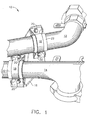
- Figure 1 is a perspective view of the clamping assembly of the present invention.
- Figure 2 is another perspective view of the clamping assembly of the present invention.
- Figure 3 is a traverse section view of the clamping assembly of the present invention in which the strap clamp is not bolted on.
- Figure 4 is a traverse section view of the clamping assembly of the present invention in which the strap clamp is bolted on.
- Figure 5 is a top view of the strap clamp of the clamping assembly of the present invention.
- Figure 6 is a traverse section view of a second embodiment of the clamping assembly of the present invention in which the strap clamp is not bolted on.
- Figure 7 is a traverse section view of a second embodiment of the clamping assembly of the present invention in which the strap clamp is bolted on.
- Figures 1 and 2 show a clamping assembly 10 for clamping two tubes 12 and 14 together.
- the tubes 12 and 14 are typically tubes used on a gas turbine engine to carry operating fluids such as fuel, oil and air, although the clamping assembly 10 can be used with tubes having other applications.
- the clamping assembly 10 shown in Figures 1 and 2 is a tube-to-tube type clamping assembly, this is only for purposes of illustration. It should be understood from the following description that the present invention is also applicable to other types of clamping assemblies, such as those for clamping tubes to the engine casing.
- the clamping assembly 10 includes a bracket 16 and a pair of strap clamps 18.
- the bracket 16 which as best seen in Figure 2 has a generally trapezoid shape, is positioned against the two tubes 12 and 14, and each tube is clamped to the bracket 16 by a respective one of the strap clamps 18, which are bolted to the bracket 16 by bolts or other suitable fasteners 20.
- the bracket 16 and strap clamps 18 are made from any suitable metal material, such as stainless steel or nickel-based alloys like Inconel.
- a wear sleeve 22 is optionally disposed between each tube 12 and 14 and its respective strap clamp 18.
- the wear sleeve 22 is made of a suitable material that will prevent undesired wear of the tubes 12 and 14 during engine operation.
- the strap clamp 18 is a thin metal piece having a generally U-shaped portion 24 that fits over the tube 12 and wear sleeve 22.
- the U-shaped portion 24 has a pair of angled leg sections 26 connected to a flat section 28.
- Each of the leg sections 26 is angled at about its midpoint so as to form an obtuse angle and define inner and outer segments 30 and 32.
- the inner segment 30 of each angled leg section 26 is joined to a respective end of the flat section 28 at an obtuse angle so that the outer segments 32 are substantially perpendicular to the flat section 28.
- a mounting flange 34 extends perpendicularly outward from the distal end of each outer segment 32.
- each mounting flange 34 is formed in each mounting flange 34 for receiving the bolts 20 to secure the mounting flanges 34 against the bracket 16.
- Side supports 38 extend from each side of each mounting flange 34 to the adjacent leg section 26 to reinforce the mounting flanges 34.
- the strap clamp 18 is made from a single stamped or machined piece of material which is bent into the desired shape.
- the unique configuration of the strap clamp 18 provides it with the necessary flexibility to close large clamp gaps while maintaining sufficient thickness to provide good fatigue capability.
- a gap 40 exists between the mounting flanges 34 and the bracket 16 because the diameter of the wear sleeve 22 surrounding the tube 12 is slightly greater than the depth of the U-shaped portion 24 when it is in an unloaded state.
- the U-shaped portion 24 contacts the wear sleeve 22 (or the tube 12 in the event a wear sleeve is not used) at three points: one on both of the inner leg segments 30 and one at the midpoint of the flat section 28.
- each angled leg section 26 is joined to a respective end of the flat section 28 are spaced from the outer surface of the wear sleeve 22.
- This configuration of the strap clamp 18 gives it sufficient flexibility to allow even unusually large clamp gaps to be closed when the strap clamp is bolted to the bracket 16.
- the mounting flanges 34 are flush with the bracket 16.
- the clamping assembly 110 differs from the clamping assembly of the first embodiment in that it utilizes a differently configured strap clamp 118.
- the strap clamp 118 has a generally U-shaped portion 124 that fits over the tube 12 and wear sleeve 22.
- the U-shaped portion 124 has a pair of straight leg sections 126 connected to a semi-oval section 128.
- the semi-oval section 128 resembles half of an oval cut lengthwise so as to define a curve having a radius of curvature that is greater at its center than at its ends.
- a mounting flange 134 extends perpendicularly outward from the distal end of each straight leg section 126.
- Side supports 138 extend from each side of each mounting flange 134 to the adjacent leg section 126 to reinforce the mounting flanges 134.
- the unique configuration of the strap clamp 118 provides it with the necessary flexibility to close large clamp gaps while maintaining sufficient thickness to provide good fatigue capability.
- a gap 40 exists between the mounting flanges 134 and the bracket 16 because the diameter of the wear sleeve 22 surrounding the tube 12 is slightly greater than the depth of the U-shaped portion 124 when it is in an unloaded state.
- the U-shaped portion 124 contacts the wear sleeve 22 (or the tube 12 in the event a wear sleeve is not used) at three points: one on both of the straight leg sections 126 and one at the midpoint of the semi-oval section 128.
- the portions of the strap clamp 118 between these points of contact are spaced from the outer surface of the wear sleeve 22 due to the elongated curvature of the semi-oval section 128.
- This configuration of the strap clamp 118 gives it sufficient flexibility to allow even unusually large clamp gaps to be closed when the strap clamp 118 is bolted to the bracket 16.
- the mounting flanges 134 are flush with the bracket 16.
Landscapes
- Engineering & Computer Science (AREA)
- General Engineering & Computer Science (AREA)
- Mechanical Engineering (AREA)
- Supports For Pipes And Cables (AREA)
- Clamps And Clips (AREA)
Applications Claiming Priority (2)
| Application Number | Priority Date | Filing Date | Title |
|---|---|---|---|
| US215860 | 1998-12-18 | ||
| US09/215,860 US6186452B1 (en) | 1998-12-18 | 1998-12-18 | Robust tube strap clamp |
Publications (2)
| Publication Number | Publication Date |
|---|---|
| EP1010928A2 true EP1010928A2 (de) | 2000-06-21 |
| EP1010928A3 EP1010928A3 (de) | 2003-01-08 |
Family
ID=22804705
Family Applications (1)
| Application Number | Title | Priority Date | Filing Date |
|---|---|---|---|
| EP99310128A Withdrawn EP1010928A3 (de) | 1998-12-18 | 1999-12-15 | Rohrschelle |
Country Status (3)
| Country | Link |
|---|---|
| US (1) | US6186452B1 (de) |
| EP (1) | EP1010928A3 (de) |
| JP (1) | JP2000234680A (de) |
Cited By (5)
| Publication number | Priority date | Publication date | Assignee | Title |
|---|---|---|---|---|
| EP1601076A3 (de) * | 2004-05-26 | 2006-02-15 | Snecma | Unverlierbarer Haltebügel und Verwendungsverfahren davon. |
| ITVR20090189A1 (it) * | 2009-11-13 | 2011-05-14 | Palladio Karting S R L | Telaio, particolarmente per go-kart |
| CN102900895A (zh) * | 2012-11-06 | 2013-01-30 | 如皋市凯凯电信器材有限公司 | 一种馈线用c形支架 |
| CN107863731A (zh) * | 2017-09-29 | 2018-03-30 | 武汉船用机械有限责任公司 | 一种电缆固定装置 |
| US11774191B2 (en) | 2017-10-05 | 2023-10-03 | Alfa Laval Corporate Ab | Heat transfer plate and a plate pack for a heat exchanger comprising a plurality of such heat transfer plates |
Families Citing this family (12)
| Publication number | Priority date | Publication date | Assignee | Title |
|---|---|---|---|---|
| US6655642B1 (en) * | 1999-09-30 | 2003-12-02 | General Electric Company | Single piece machined strap clamp |
| US20040257802A1 (en) * | 2003-06-18 | 2004-12-23 | Jacek Helenowski | Support rod for a light source |
| US8025258B2 (en) * | 2006-11-15 | 2011-09-27 | Richard Eldridge | Electrical wire bracket device |
| JP5011985B2 (ja) * | 2006-12-01 | 2012-08-29 | トヨタ自動車株式会社 | 燃料電池用ガス配管システム及び燃料電池搭載車両 |
| US8240939B2 (en) * | 2008-04-16 | 2012-08-14 | Lego A/S | Metal to plastic connector for toy structures |
| US20130118627A1 (en) * | 2011-11-14 | 2013-05-16 | United Technologies Corporation | Tuned response duct clamp |
| DE112015004987B4 (de) | 2014-11-03 | 2025-12-04 | Cummins Inc. | Verfahren zum stützen von ladeluftrohren und handhaben von wärmeausdehnung mittels einer verschleisshülse |
| JP6347226B2 (ja) | 2015-04-16 | 2018-06-27 | トヨタ自動車株式会社 | スタビライザバー取付装置、スタビライザバー取付用ブラケット |
| JP7240852B2 (ja) * | 2017-11-08 | 2023-03-16 | イートン インテリジェント パワー リミテッド | 建物内の非構造部品用耐震クランプ |
| CN108612916A (zh) * | 2018-05-18 | 2018-10-02 | 云南电网有限责任公司电力科学研究院 | 一种基于输电杆塔的蒸汽管道 |
| US11703155B2 (en) | 2020-09-21 | 2023-07-18 | Jeremias Inc. | Exhaust pipe accessory and uses thereof |
| US12590701B2 (en) | 2022-12-20 | 2026-03-31 | Jeremias Inc. | Pass-through device for a chimney |
Family Cites Families (11)
| Publication number | Priority date | Publication date | Assignee | Title |
|---|---|---|---|---|
| US2972461A (en) * | 1959-04-27 | 1961-02-21 | Robert L Brown | Hose clip |
| US3042352A (en) * | 1960-04-22 | 1962-07-03 | George F Stamper | Pipe hanger |
| US3227406A (en) * | 1963-07-15 | 1966-01-04 | North American Aviation Inc | High temperature clamp and method of making same |
| US4146203A (en) * | 1977-10-20 | 1979-03-27 | Williams Robert O | Pipe hanger supports |
| DE3113161C2 (de) * | 1981-04-01 | 1984-05-10 | Rasmussen Gmbh, 6457 Maintal | Schelle zum Einspannen von Gegenständen, wie Behältern, Rohren oder dergleichen |
| IT222671Z2 (it) * | 1991-07-05 | 1995-04-24 | Tassalini Flli | Reggitubo |
| US5297890A (en) * | 1992-02-20 | 1994-03-29 | Simpson Strong-Tie Company, Inc. | Wood-to-pipe connection |
| US5271588A (en) | 1992-07-17 | 1993-12-21 | General Electric Company | Multi-piece tube clamp |
| JPH0816517B2 (ja) * | 1992-07-17 | 1996-02-21 | ゼネラル・エレクトリック・カンパニイ | クランプ |
| US5582058A (en) * | 1995-01-10 | 1996-12-10 | Knudson; Giltner J. | Girdling article and method |
| US6079674A (en) * | 1998-04-08 | 2000-06-27 | Snyder; Darryl L. | Suspension clamp having flexible retaining arm |
-
1998
- 1998-12-18 US US09/215,860 patent/US6186452B1/en not_active Expired - Lifetime
-
1999
- 1999-11-30 JP JP11338910A patent/JP2000234680A/ja not_active Withdrawn
- 1999-12-15 EP EP99310128A patent/EP1010928A3/de not_active Withdrawn
Non-Patent Citations (1)
| Title |
|---|
| None |
Cited By (6)
| Publication number | Priority date | Publication date | Assignee | Title |
|---|---|---|---|---|
| EP1601076A3 (de) * | 2004-05-26 | 2006-02-15 | Snecma | Unverlierbarer Haltebügel und Verwendungsverfahren davon. |
| ITVR20090189A1 (it) * | 2009-11-13 | 2011-05-14 | Palladio Karting S R L | Telaio, particolarmente per go-kart |
| CN102900895A (zh) * | 2012-11-06 | 2013-01-30 | 如皋市凯凯电信器材有限公司 | 一种馈线用c形支架 |
| CN107863731A (zh) * | 2017-09-29 | 2018-03-30 | 武汉船用机械有限责任公司 | 一种电缆固定装置 |
| CN107863731B (zh) * | 2017-09-29 | 2019-12-17 | 武汉船用机械有限责任公司 | 一种电缆固定装置 |
| US11774191B2 (en) | 2017-10-05 | 2023-10-03 | Alfa Laval Corporate Ab | Heat transfer plate and a plate pack for a heat exchanger comprising a plurality of such heat transfer plates |
Also Published As
| Publication number | Publication date |
|---|---|
| US6186452B1 (en) | 2001-02-13 |
| EP1010928A3 (de) | 2003-01-08 |
| JP2000234680A (ja) | 2000-08-29 |
Similar Documents
| Publication | Publication Date | Title |
|---|---|---|
| US6186452B1 (en) | Robust tube strap clamp | |
| US8607431B2 (en) | Ring for mounting a structure to a shaft | |
| EP0523970B1 (de) | Vibrationsisolierende Dichtungsklammer für Rohrleitungsanschlüsse | |
| EP2245358B1 (de) | Einbolzen-bandspanner mit abgedichteter zentraler rippe und überlappende rohrverbindung damit | |
| KR100685181B1 (ko) | 다중방향성 터빈 심 시일 | |
| US10711920B2 (en) | Clamping device and an associated method thereof | |
| US5090742A (en) | Pipe harness clamp | |
| US7320486B2 (en) | Pipe clamp | |
| EP1108901A2 (de) | Abdichtungsbefestigungsvorrichtung | |
| US6079753A (en) | Segmented flange including a shim | |
| US4778342A (en) | Turbine blade retainer | |
| CN1320201A (zh) | 夹箍附件 | |
| US5961153A (en) | Exhaust repair kit for exhaust system and methods therefor | |
| US20220260188A1 (en) | Coupling Having Visual Installation Indicators | |
| US20060012133A1 (en) | Rings for mounting structures to shafts and methods of using such rings | |
| US5755464A (en) | Segmented flange structure including a shim | |
| US10648478B2 (en) | Fan case bushing | |
| US6655642B1 (en) | Single piece machined strap clamp | |
| JPH04342830A (ja) | せん断ワイヤフランジ継手 | |
| JP2020527661A (ja) | 排気ガス過給機のための結合具及び排気ガス過給機 | |
| JP3929187B2 (ja) | 管継手構造 | |
| JPH11141764A (ja) | 分割型管継手 | |
| EP1333186B1 (de) | Klammer | |
| US6012741A (en) | Conduit connecting arrangement and method | |
| JPS5970813A (ja) | 蒸気タ−ビン伸縮管継手のリテ−ナ−リング |
Legal Events
| Date | Code | Title | Description |
|---|---|---|---|
| PUAI | Public reference made under article 153(3) epc to a published international application that has entered the european phase |
Free format text: ORIGINAL CODE: 0009012 |
|
| AK | Designated contracting states |
Kind code of ref document: A2 Designated state(s): AT BE CH CY DE DK ES FI FR GB GR IE IT LI LU MC NL PT SE |
|
| AX | Request for extension of the european patent |
Free format text: AL;LT;LV;MK;RO;SI |
|
| PUAL | Search report despatched |
Free format text: ORIGINAL CODE: 0009013 |
|
| AK | Designated contracting states |
Kind code of ref document: A3 Designated state(s): AT BE CH CY DE DK ES FI FR GB GR IE IT LI LU MC NL PT SE |
|
| AX | Request for extension of the european patent |
Free format text: AL;LT;LV;MK;RO;SI |
|
| 17P | Request for examination filed |
Effective date: 20030708 |
|
| AKX | Designation fees paid |
Designated state(s): DE FR GB IT |
|
| 17Q | First examination report despatched |
Effective date: 20040209 |
|
| STAA | Information on the status of an ep patent application or granted ep patent |
Free format text: STATUS: THE APPLICATION IS DEEMED TO BE WITHDRAWN |
|
| 18D | Application deemed to be withdrawn |
Effective date: 20050809 |