EP1010945A2 - Dispositif d'injection de carburant pour chambres de combustion de turbines à gaz - Google Patents
Dispositif d'injection de carburant pour chambres de combustion de turbines à gaz Download PDFInfo
- Publication number
- EP1010945A2 EP1010945A2 EP99308025A EP99308025A EP1010945A2 EP 1010945 A2 EP1010945 A2 EP 1010945A2 EP 99308025 A EP99308025 A EP 99308025A EP 99308025 A EP99308025 A EP 99308025A EP 1010945 A2 EP1010945 A2 EP 1010945A2
- Authority
- EP
- European Patent Office
- Prior art keywords
- fuel
- inlet module
- cavity
- injection system
- bars
- Prior art date
- Legal status (The legal status is an assumption and is not a legal conclusion. Google has not performed a legal analysis and makes no representation as to the accuracy of the status listed.)
- Granted
Links
Images


Classifications
-
- F—MECHANICAL ENGINEERING; LIGHTING; HEATING; WEAPONS; BLASTING
- F23—COMBUSTION APPARATUS; COMBUSTION PROCESSES
- F23R—GENERATING COMBUSTION PRODUCTS OF HIGH PRESSURE OR HIGH VELOCITY, e.g. GAS-TURBINE COMBUSTION CHAMBERS
- F23R3/00—Continuous combustion chambers using liquid or gaseous fuel
- F23R3/02—Continuous combustion chambers using liquid or gaseous fuel characterised by the air-flow or gas-flow configuration
- F23R3/16—Continuous combustion chambers using liquid or gaseous fuel characterised by the air-flow or gas-flow configuration with devices inside the flame tube or the combustion chamber to influence the air or gas flow
- F23R3/18—Flame stabilising means, e.g. flame holders for after-burners of jet-propulsion plants
- F23R3/20—Flame stabilising means, e.g. flame holders for after-burners of jet-propulsion plants incorporating fuel injection means
-
- F—MECHANICAL ENGINEERING; LIGHTING; HEATING; WEAPONS; BLASTING
- F23—COMBUSTION APPARATUS; COMBUSTION PROCESSES
- F23R—GENERATING COMBUSTION PRODUCTS OF HIGH PRESSURE OR HIGH VELOCITY, e.g. GAS-TURBINE COMBUSTION CHAMBERS
- F23R3/00—Continuous combustion chambers using liquid or gaseous fuel
- F23R3/02—Continuous combustion chambers using liquid or gaseous fuel characterised by the air-flow or gas-flow configuration
- F23R3/04—Air inlet arrangements
- F23R3/10—Air inlet arrangements for primary air
- F23R3/12—Air inlet arrangements for primary air inducing a vortex
-
- F—MECHANICAL ENGINEERING; LIGHTING; HEATING; WEAPONS; BLASTING
- F23—COMBUSTION APPARATUS; COMBUSTION PROCESSES
- F23R—GENERATING COMBUSTION PRODUCTS OF HIGH PRESSURE OR HIGH VELOCITY, e.g. GAS-TURBINE COMBUSTION CHAMBERS
- F23R3/00—Continuous combustion chambers using liquid or gaseous fuel
- F23R3/28—Continuous combustion chambers using liquid or gaseous fuel characterised by the fuel supply
Definitions
- the present invention relates to a gas turbine engine combustor having at least one trapped vortex cavity and, more particularly, to a fuel injector bar used for injecting fuel into such cavity and flow passages of a dome inlet module providing high inlet air flows to the combustion chamber.
- a fuel injection system it would be desirable for a fuel injection system to be developed in which the cavity sections of a combustion chamber and the flow passages providing air flow thereto can be provided fuel in a simpler design requiring less space. Further, it would be desirable if such fuel injection system would be constructed so as to interface with the dome inlet module in a manner which enables easy access to the fuel injectors for repair and replacement.
- a fuel injection system for a gas turbine engine combustor wherein the combustor includes a dome inlet module having a plurality of flow passages formed therein and at least one cavity formed in a liner downstream of said dome inlet module.
- the fuel injection system includes a fuel supply and a plurality of fuel injector bars positioned circumferentially around and interfacing with the inlet dome module.
- the fuel injector bars are in flow communication with the fuel supply, with each of the fuel injector bars further including a body portion having an upstream end, a downstream end, and a pair of sides.
- Injectors are provided in openings formed in the body portion and are in flow communication with the fuel supply, whereby fuel is provided to the dome inlet module flow passages and/or the cavity through the fuel injector bars.
- a method of operating a gas turbine engine combustor includes a dome inlet module having a plurality of flow passages formed therein and at least one cavity formed within a combustion chamber by a liner downstream of the dome inlet module.
- the method includes the steps of injecting fuel into an upstream end of the cavity, injecting air into the cavity to create a trapped vortex of fuel and air therein, igniting the mixture of fuel and air in the cavity to form combustion gases, providing a flow of main stream air from a compressor upstream of the dome inlet module into and through the flow passages, and exhausting the cavity combustion gases across a downstream end of the dome inlet module so as to interact with the main stream air.
- the method may also include the steps of injecting fuel into the dome inlet module flow passages so as to mix with the main stream air and igniting the mixture of fuel and main stream air by the cavity combustion gases exhausting across the dome inlet module downstream end.
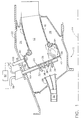
- Fig. 1 depicts a combustor 10 which comprises a hollow body defining a combustion chamber 12 therein.
- Combustor 10 is generally annular in form about an axis 14 and is further comprised of an outer liner 16, an inner liner 18, and a dome inlet module designated generally by the numeral 20.
- a casing 22 is preferably positioned around combustor 10 so that an outer radial passage 24 is formed between casing 22 and outer liner 16 and an inner passage 26 is defined between casing 22 and inner liner 18.
- dome inlet module 20 may be like that shown and disclosed in the U.S. Patent 5,619,855 to Burrus, which is also owned by the assignee of the current invention.
- Fig. 1 depicts combustor 10 has having a different dome inlet module 20, where it is separate from a diffuser 28 located upstream thereof for directing air flow from an exit end 30 of a compressor.
- Dome inlet module 20, which is connected to outer liner 16 and inner liner 18, preferably includes an outer vane 32, an inner vane 34, and one or middle vanes 36 disposed therebetween so as to form a plurality of flow passages 38. While three such flow passages are shown in Fig. 1, there may be either more or less depending upon the number of middle vanes 36 provided.
- dome inlet module 20 is positioned in substantial alignment with the outlet of diffuser 28 so that a main stream air flow is directed unimpeded into combustion chamber 12.
- outer and inner vanes 32 and 34 extend axially upstream in order to better receive the main stream air flow within flow passages 38 of dome inlet module 20.
- a trapped vortex cavity depicted generally by the number 40, formed at least in outer liner 16.
- a similar trapped vortex cavity 42 is preferably provided in inner liner 18 as well. Cavities 40 and 42 are utilized to provide a trapped vortex of fuel and air, as discussed in the aforementioned '855 patent and depicted schematically in cavity 42 of Fig. 1.
- trapped vortex cavities 40 and 42 are incorporated immediately downstream of dome inlet module 20 and shown as being substantially rectangular in shape (although cavities 40 and 42 may be configured as arcuate in cross-section).
- Cavity 40 is open to combustion chamber 12 so that it is formed by an aft wall 44, a forward wall 46, and an outer wall 48 formed therebetween which preferably is substantially parallel to outer liner 16.
- cavity 42 is open to combustion chamber 12 so that it is formed by an aft wall 45, a forward wall 47, and an inner wall 49 formed therebetween which preferably is substantially parallel to inner liner 18.
- fuel injector bars 50 are configured to be inserted into dome inlet module 20 through engine casing 22 around combustor 10. Depending upon the design of dome inlet module 20, each fuel injector bar 50 is then inserted into slots provided in vanes 32, 34 and 36 (see Fig. 4) or integrally therewith through openings provided therein. Fuel injector bars 50 are then in flow communication with a fuel supply 52, preferably via separate fuel lines 54 and 56, in order to inject fuel into cavities 40 and 42 and flow passages 38.
- each fuel injector bar 50 has a body portion 58 having an upstream end 60, a downstream end 62, and a pair of sides 64 and 66 (see Fig. 3).
- upstream end 60 is preferably aerodynamically shaped while downstream end 62 has, but is not limited to, a bluff surface.
- a first injector 68 is positioned within an opening 70 located at an upper location of downstream end 62 and a second injector 72 is positioned within an opening 74 located at a lower location of downstream end 62.
- a pair of oppositely disposed openings 76 and 78 in sides 64 and 66, respectively, are provided with injectors 80 and 82 to inject fuel within each flow passage 38 of dome inlet module 20.
- body portion 58 operates as a heat shield to the fuel flowing therethrough to injectors 68, 72, 80 and 82. Since it is preferred that injectors 68 and 72 be supplied with fuel separately from injectors 80 and 82 via fuel lines 54 and 56, first and second passages 84 and 86 are provided within fuel injector bars 50. Fuel line 54 is brazed to first passage 84 so as to provide flow communication and direct fuel to injectors 68 and 72 while fuel line 56 is brazed to second passage 86 so as to provide flow communication and direct fuel to injectors 80 and 82. It will be understood that injectors 68, 72, 80 and 82 are well known in the art and may be atomizers or other similar means used for fuel injection.
- fuel injector bars 50 be constructed to have a middle portion 88 housed within body portion 58 of fuel injection bars 50 with first and second passages 84 and 86 formed therein.
- Middle portion 88 is optimally made of ceramic or a similarly insulating material to minimize the heat transferred to the fuel.
- An additional air gap 90 may also be provided about middle portion 88 where available in order to further insulate the fuel flowing therethrough. It will be appreciated that middle portion 88 is maintained in position within body portion 58 at least by the attachment of fuel lines 54 and 56 at an upper end thereof.
- combustor 10 utilizes the combustion regions within cavities 40 and 42 as the pilot, with fuel only being provided through injectors 68 and 72 of fuel injector bars 50. Air is also injected into cavities 40 and 42 via passages 92 and 94 located at the intersection of aft walls 44 and 45 with outer wall 48 and inner wall 49, respectively, as well as passages 96 and 98 located at the intersection of forward walls 46 and 47 with outer wall 48 and inner wall 49. In this way, a trapped vortex of fuel and air is created in cavities 40 and 42. Thereafter, the mixture of fuel and air within cavities 40 and 42 are ignited, such as by igniter 100, to form combustion gases therein.
Landscapes
- Engineering & Computer Science (AREA)
- Chemical & Material Sciences (AREA)
- Combustion & Propulsion (AREA)
- Mechanical Engineering (AREA)
- General Engineering & Computer Science (AREA)
- Pre-Mixing And Non-Premixing Gas Burner (AREA)
Applications Claiming Priority (2)
| Application Number | Priority Date | Filing Date | Title |
|---|---|---|---|
| US215863 | 1998-12-18 | ||
| US09/215,863 US6295801B1 (en) | 1998-12-18 | 1998-12-18 | Fuel injector bar for gas turbine engine combustor having trapped vortex cavity |
Publications (3)
| Publication Number | Publication Date |
|---|---|
| EP1010945A2 true EP1010945A2 (fr) | 2000-06-21 |
| EP1010945A3 EP1010945A3 (fr) | 2002-02-20 |
| EP1010945B1 EP1010945B1 (fr) | 2008-06-25 |
Family
ID=22804718
Family Applications (1)
| Application Number | Title | Priority Date | Filing Date |
|---|---|---|---|
| EP99308025A Expired - Lifetime EP1010945B1 (fr) | 1998-12-18 | 1999-10-12 | Dispositif d'injection de carburant pour chambres de combustion de turbines à gaz |
Country Status (4)
| Country | Link |
|---|---|
| US (1) | US6295801B1 (fr) |
| EP (1) | EP1010945B1 (fr) |
| JP (1) | JP4406127B2 (fr) |
| DE (1) | DE69938957D1 (fr) |
Cited By (11)
| Publication number | Priority date | Publication date | Assignee | Title |
|---|---|---|---|---|
| EP1524473A1 (fr) * | 2003-10-13 | 2005-04-20 | Siemens Aktiengesellschaft | Procédé et dispositif pour brûler du carburant |
| EP1371906A3 (fr) * | 2002-06-11 | 2007-04-04 | General Electric Company | Chemise tubulaire de chambre de combustion de turbine à gaz avec cavité pour la création de vortex piégés |
| DE102006004840A1 (de) * | 2006-02-02 | 2007-08-23 | Rolls-Royce Deutschland Ltd & Co Kg | Gasturbinenbrennkammer mit Kraftstoffeinspritzung über den gesamten Brennkammerring |
| WO2008090202A1 (fr) * | 2007-01-25 | 2008-07-31 | Siemens Aktiengesellschaft | Diffuseur permettant de ralentir un fluide comprimé |
| EP2475934A4 (fr) * | 2009-09-13 | 2015-02-11 | Lean Flame Inc | Appareil de pré-mélange à tourbillon pour appareil à combustion |
| EP2354663A3 (fr) * | 2010-01-29 | 2015-03-11 | United Technologies Corporation | Chambre de combustion de turbine à gaz dotée d'une combustion étagée |
| EP3246630A1 (fr) * | 2016-04-18 | 2017-11-22 | Dresser Rand Company | Chambre de combustion tubulaire unique à vortex |
| CN109668174A (zh) * | 2017-10-17 | 2019-04-23 | 通用电气公司 | 燃气涡轮发动机的驻涡燃烧器及其操作方法 |
| CN116557905A (zh) * | 2023-05-06 | 2023-08-08 | 清华大学 | 环形扩压器及燃烧室 |
| CN116592393A (zh) * | 2023-05-24 | 2023-08-15 | 中国航空发动机研究院 | 一种燃烧设备及燃气发动机 |
| EP4575316A1 (fr) * | 2023-12-22 | 2025-06-25 | General Electric Company | Moteur à turbine comprenant une section de combustion avec une buse de carburant |
Families Citing this family (56)
| Publication number | Priority date | Publication date | Assignee | Title |
|---|---|---|---|---|
| US6481209B1 (en) * | 2000-06-28 | 2002-11-19 | General Electric Company | Methods and apparatus for decreasing combustor emissions with swirl stabilized mixer |
| US8272219B1 (en) * | 2000-11-03 | 2012-09-25 | General Electric Company | Gas turbine engine combustor having trapped dual vortex cavity |
| US6564555B2 (en) * | 2001-05-24 | 2003-05-20 | Allison Advanced Development Company | Apparatus for forming a combustion mixture in a gas turbine engine |
| US7003961B2 (en) * | 2001-07-23 | 2006-02-28 | Ramgen Power Systems, Inc. | Trapped vortex combustor |
| US6694743B2 (en) | 2001-07-23 | 2004-02-24 | Ramgen Power Systems, Inc. | Rotary ramjet engine with flameholder extending to running clearance at engine casing interior wall |
| US7603841B2 (en) * | 2001-07-23 | 2009-10-20 | Ramgen Power Systems, Llc | Vortex combustor for low NOx emissions when burning lean premixed high hydrogen content fuel |
| US6820424B2 (en) * | 2001-09-12 | 2004-11-23 | Allison Advanced Development Company | Combustor module |
| US6786049B2 (en) | 2002-05-22 | 2004-09-07 | Hamilton Sundstrand | Fuel supply control for a gas turbine including multiple solenoid valves |
| US6851263B2 (en) | 2002-10-29 | 2005-02-08 | General Electric Company | Liner for a gas turbine engine combustor having trapped vortex cavity |
| US6868676B1 (en) * | 2002-12-20 | 2005-03-22 | General Electric Company | Turbine containing system and an injector therefor |
| GB2397373B (en) * | 2003-01-18 | 2005-09-14 | Rolls Royce Plc | Gas diffusion arrangement |
| AU2004284398B2 (en) * | 2003-10-03 | 2009-12-17 | Alm Blueflame, Llc | Combustion method and apparatus for carrying out same |
| US7325402B2 (en) | 2004-08-04 | 2008-02-05 | Siemens Power Generation, Inc. | Pilot nozzle heat shield having connected tangs |
| US20060107667A1 (en) * | 2004-11-22 | 2006-05-25 | Haynes Joel M | Trapped vortex combustor cavity manifold for gas turbine engine |
| ATE366896T1 (de) * | 2005-02-04 | 2007-08-15 | Enel Produzione Spa | Dämpfung von thermoakustischen schwingungen in einer gasturbinenbrennkammer mit ringförmiger kammer |
| US7437876B2 (en) * | 2005-03-25 | 2008-10-21 | General Electric Company | Augmenter swirler pilot |
| US7225623B2 (en) * | 2005-08-23 | 2007-06-05 | General Electric Company | Trapped vortex cavity afterburner |
| US7467518B1 (en) | 2006-01-12 | 2008-12-23 | General Electric Company | Externally fueled trapped vortex cavity augmentor |
| US7942006B2 (en) * | 2007-03-26 | 2011-05-17 | Honeywell International Inc. | Combustors and combustion systems for gas turbine engines |
| US8322142B2 (en) * | 2007-05-01 | 2012-12-04 | Flexenergy Energy Systems, Inc. | Trapped vortex combustion chamber |
| US8800290B2 (en) * | 2007-12-18 | 2014-08-12 | United Technologies Corporation | Combustor |
| US8640464B2 (en) * | 2009-02-23 | 2014-02-04 | Williams International Co., L.L.C. | Combustion system |
| US8763400B2 (en) * | 2009-08-04 | 2014-07-01 | General Electric Company | Aerodynamic pylon fuel injector system for combustors |
| US8534040B2 (en) * | 2010-11-11 | 2013-09-17 | General Electric Company | Apparatus and method for igniting a combustor |
| US8863525B2 (en) | 2011-01-03 | 2014-10-21 | General Electric Company | Combustor with fuel staggering for flame holding mitigation |
| US8893500B2 (en) | 2011-05-18 | 2014-11-25 | Solar Turbines Inc. | Lean direct fuel injector |
| US8919132B2 (en) | 2011-05-18 | 2014-12-30 | Solar Turbines Inc. | Method of operating a gas turbine engine |
| US8950189B2 (en) * | 2011-06-28 | 2015-02-10 | United Technologies Corporation | Gas turbine engine staged fuel injection using adjacent bluff body and swirler fuel injectors |
| US8919125B2 (en) * | 2011-07-06 | 2014-12-30 | General Electric Company | Apparatus and systems relating to fuel injectors and fuel passages in gas turbine engines |
| US9182124B2 (en) | 2011-12-15 | 2015-11-10 | Solar Turbines Incorporated | Gas turbine and fuel injector for the same |
| US9074773B2 (en) * | 2012-02-07 | 2015-07-07 | General Electric Company | Combustor assembly with trapped vortex cavity |
| CN103277811B (zh) * | 2013-05-10 | 2015-10-28 | 南京航空航天大学 | 单凹腔驻涡燃烧室 |
| US20150323185A1 (en) | 2014-05-07 | 2015-11-12 | General Electric Compamy | Turbine engine and method of assembling thereof |
| RU2015156419A (ru) | 2015-12-28 | 2017-07-04 | Дженерал Электрик Компани | Узел топливной форсунки, выполненный со стабилизатором пламени предварительно перемешанной смеси |
| US10295190B2 (en) | 2016-11-04 | 2019-05-21 | General Electric Company | Centerbody injector mini mixer fuel nozzle assembly |
| US10393382B2 (en) | 2016-11-04 | 2019-08-27 | General Electric Company | Multi-point injection mini mixing fuel nozzle assembly |
| US10465909B2 (en) | 2016-11-04 | 2019-11-05 | General Electric Company | Mini mixing fuel nozzle assembly with mixing sleeve |
| US10352569B2 (en) | 2016-11-04 | 2019-07-16 | General Electric Company | Multi-point centerbody injector mini mixing fuel nozzle assembly |
| US10724740B2 (en) | 2016-11-04 | 2020-07-28 | General Electric Company | Fuel nozzle assembly with impingement purge |
| US10634353B2 (en) | 2017-01-12 | 2020-04-28 | General Electric Company | Fuel nozzle assembly with micro channel cooling |
| US10823418B2 (en) | 2017-03-02 | 2020-11-03 | General Electric Company | Gas turbine engine combustor comprising air inlet tubes arranged around the combustor |
| US10976053B2 (en) | 2017-10-25 | 2021-04-13 | General Electric Company | Involute trapped vortex combustor assembly |
| US10976052B2 (en) | 2017-10-25 | 2021-04-13 | General Electric Company | Volute trapped vortex combustor assembly |
| US10890329B2 (en) | 2018-03-01 | 2021-01-12 | General Electric Company | Fuel injector assembly for gas turbine engine |
| US11181269B2 (en) | 2018-11-15 | 2021-11-23 | General Electric Company | Involute trapped vortex combustor assembly |
| US10935245B2 (en) | 2018-11-20 | 2021-03-02 | General Electric Company | Annular concentric fuel nozzle assembly with annular depression and radial inlet ports |
| US11073114B2 (en) | 2018-12-12 | 2021-07-27 | General Electric Company | Fuel injector assembly for a heat engine |
| US11286884B2 (en) | 2018-12-12 | 2022-03-29 | General Electric Company | Combustion section and fuel injector assembly for a heat engine |
| US11156360B2 (en) | 2019-02-18 | 2021-10-26 | General Electric Company | Fuel nozzle assembly |
| US11480337B2 (en) * | 2019-11-26 | 2022-10-25 | Collins Engine Nozzles, Inc. | Fuel injection for integral combustor and turbine vane |
| CN112610982B (zh) * | 2020-12-16 | 2022-03-08 | 江苏科技大学 | 一种具有抑制主流向凹腔卷吸的驻涡燃烧室头部装置 |
| US11859819B2 (en) | 2021-10-15 | 2024-01-02 | General Electric Company | Ceramic composite combustor dome and liners |
| US12454909B2 (en) | 2021-12-03 | 2025-10-28 | General Electric Company | Combustor size rating for a gas turbine engine using hydrogen fuel |
| US12331932B2 (en) | 2022-01-31 | 2025-06-17 | General Electric Company | Turbine engine fuel mixer |
| US12215866B2 (en) | 2022-02-18 | 2025-02-04 | General Electric Company | Combustor for a turbine engine having a fuel-air mixer including a set of mixing passages |
| US20240401807A1 (en) * | 2023-05-31 | 2024-12-05 | General Electric Company | Turbine engine including a combustor |
Family Cites Families (24)
| Publication number | Priority date | Publication date | Assignee | Title |
|---|---|---|---|---|
| US3034297A (en) * | 1958-12-15 | 1962-05-15 | Bristol Siddeley Engines Ltd | Combustion chambers |
| GB1048968A (en) * | 1964-05-08 | 1966-11-23 | Rolls Royce | Combustion chamber for a gas turbine engine |
| GB1253097A (fr) * | 1969-03-21 | 1971-11-10 | ||
| US3675419A (en) * | 1970-10-26 | 1972-07-11 | United Aircraft Corp | Combustion chamber having swirling flow |
| US4563875A (en) * | 1974-07-24 | 1986-01-14 | Howald Werner E | Combustion apparatus including an air-fuel premixing chamber |
| US3973390A (en) * | 1974-12-18 | 1976-08-10 | United Technologies Corporation | Combustor employing serially staged pilot combustion, fuel vaporization, and primary combustion zones |
| DE2937631A1 (de) * | 1979-09-18 | 1981-04-02 | Daimler-Benz Ag, 7000 Stuttgart | Brennkammer fuer gasturbinen |
| DE3261484D1 (en) * | 1981-03-04 | 1985-01-24 | Bbc Brown Boveri & Cie | Annular combustion chamber with an annular burner for gas turbines |
| US4901527A (en) * | 1988-02-18 | 1990-02-20 | General Electric Company | Low turbulence flame holder mount |
| US4903480A (en) * | 1988-09-16 | 1990-02-27 | General Electric Company | Hypersonic scramjet engine fuel injector |
| US5207064A (en) * | 1990-11-21 | 1993-05-04 | General Electric Company | Staged, mixed combustor assembly having low emissions |
| EP0550126A1 (fr) * | 1992-01-02 | 1993-07-07 | General Electric Company | Bouclier thermique pour post-combusteur |
| US5335501A (en) * | 1992-11-16 | 1994-08-09 | General Electric Company | Flow spreading diffuser |
| FR2706588B1 (fr) * | 1993-06-16 | 1995-07-21 | Snecma | Système d'injection de carburant pour chambre de combustion. |
| EP0741850B1 (fr) * | 1994-01-24 | 1998-05-27 | Siemens Aktiengesellschaft | Procede de combustion d'un combustible dans de l'air comprime |
| JP2950720B2 (ja) * | 1994-02-24 | 1999-09-20 | 株式会社東芝 | ガスタービン燃焼装置およびその燃焼制御方法 |
| US5657632A (en) * | 1994-11-10 | 1997-08-19 | Westinghouse Electric Corporation | Dual fuel gas turbine combustor |
| US5813232A (en) * | 1995-06-05 | 1998-09-29 | Allison Engine Company, Inc. | Dry low emission combustor for gas turbine engines |
| US5619855A (en) | 1995-06-07 | 1997-04-15 | General Electric Company | High inlet mach combustor for gas turbine engine |
| US5791148A (en) | 1995-06-07 | 1998-08-11 | General Electric Company | Liner of a gas turbine engine combustor having trapped vortex cavity |
| US5647215A (en) * | 1995-11-07 | 1997-07-15 | Westinghouse Electric Corporation | Gas turbine combustor with turbulence enhanced mixing fuel injectors |
| DE19614001A1 (de) * | 1996-04-09 | 1997-10-16 | Abb Research Ltd | Brennkammer |
| US6047550A (en) * | 1996-05-02 | 2000-04-11 | General Electric Co. | Premixing dry low NOx emissions combustor with lean direct injection of gas fuel |
| US6125627A (en) * | 1998-08-11 | 2000-10-03 | Allison Advanced Development Company | Method and apparatus for spraying fuel within a gas turbine engine |
-
1998
- 1998-12-18 US US09/215,863 patent/US6295801B1/en not_active Expired - Fee Related
-
1999
- 1999-10-12 EP EP99308025A patent/EP1010945B1/fr not_active Expired - Lifetime
- 1999-10-12 DE DE69938957T patent/DE69938957D1/de not_active Expired - Lifetime
- 1999-10-15 JP JP29307199A patent/JP4406127B2/ja not_active Expired - Fee Related
Cited By (18)
| Publication number | Priority date | Publication date | Assignee | Title |
|---|---|---|---|---|
| EP1371906A3 (fr) * | 2002-06-11 | 2007-04-04 | General Electric Company | Chemise tubulaire de chambre de combustion de turbine à gaz avec cavité pour la création de vortex piégés |
| WO2005038348A1 (fr) * | 2003-10-13 | 2005-04-28 | Siemens Aktiengesellschaft | Procede et dispositif de combustion d'un combustible |
| EP1524473A1 (fr) * | 2003-10-13 | 2005-04-20 | Siemens Aktiengesellschaft | Procédé et dispositif pour brûler du carburant |
| DE102006004840A1 (de) * | 2006-02-02 | 2007-08-23 | Rolls-Royce Deutschland Ltd & Co Kg | Gasturbinenbrennkammer mit Kraftstoffeinspritzung über den gesamten Brennkammerring |
| US7966818B2 (en) | 2006-02-02 | 2011-06-28 | Rolls-Royce Deutschland Ltd & Co Kg | Gas turbine combustion chamber with fuel injection over an entire combustion chamber annulus |
| WO2008090202A1 (fr) * | 2007-01-25 | 2008-07-31 | Siemens Aktiengesellschaft | Diffuseur permettant de ralentir un fluide comprimé |
| US8714922B2 (en) | 2007-01-25 | 2014-05-06 | Siemens Aktiengesellschaft | Diffuser for decelerating a compressed fluid |
| EP2475855A4 (fr) * | 2009-09-13 | 2015-04-29 | Lean Flame Inc | Appareil de pré-mélange d'admission pour appareil à combustion |
| EP2475934A4 (fr) * | 2009-09-13 | 2015-02-11 | Lean Flame Inc | Appareil de pré-mélange à tourbillon pour appareil à combustion |
| EP2354663A3 (fr) * | 2010-01-29 | 2015-03-11 | United Technologies Corporation | Chambre de combustion de turbine à gaz dotée d'une combustion étagée |
| EP3246630A1 (fr) * | 2016-04-18 | 2017-11-22 | Dresser Rand Company | Chambre de combustion tubulaire unique à vortex |
| CN109668174A (zh) * | 2017-10-17 | 2019-04-23 | 通用电气公司 | 燃气涡轮发动机的驻涡燃烧器及其操作方法 |
| EP3473818A1 (fr) * | 2017-10-17 | 2019-04-24 | General Electric Company | Air tourbillonnant en vrac tangentiel dans une chambre de combustion vortex piégée pour moteur à turbine à gaz |
| US10823422B2 (en) | 2017-10-17 | 2020-11-03 | General Electric Company | Tangential bulk swirl air in a trapped vortex combustor for a gas turbine engine |
| CN109668174B (zh) * | 2017-10-17 | 2021-08-24 | 通用电气公司 | 燃气涡轮发动机的驻涡燃烧器及其操作方法 |
| CN116557905A (zh) * | 2023-05-06 | 2023-08-08 | 清华大学 | 环形扩压器及燃烧室 |
| CN116592393A (zh) * | 2023-05-24 | 2023-08-15 | 中国航空发动机研究院 | 一种燃烧设备及燃气发动机 |
| EP4575316A1 (fr) * | 2023-12-22 | 2025-06-25 | General Electric Company | Moteur à turbine comprenant une section de combustion avec une buse de carburant |
Also Published As
| Publication number | Publication date |
|---|---|
| JP4406127B2 (ja) | 2010-01-27 |
| EP1010945B1 (fr) | 2008-06-25 |
| US6295801B1 (en) | 2001-10-02 |
| DE69938957D1 (de) | 2008-08-07 |
| JP2000193243A (ja) | 2000-07-14 |
| EP1010945A3 (fr) | 2002-02-20 |
Similar Documents
| Publication | Publication Date | Title |
|---|---|---|
| EP1010945B1 (fr) | Dispositif d'injection de carburant pour chambres de combustion de turbines à gaz | |
| US6286298B1 (en) | Apparatus and method for rich-quench-lean (RQL) concept in a gas turbine engine combustor having trapped vortex cavity | |
| US8272219B1 (en) | Gas turbine engine combustor having trapped dual vortex cavity | |
| EP1010944B1 (fr) | Dispositf de refroidissement et de connexion pour la chemise d'une chambre de combustion pour une turbine à gaz | |
| US3765178A (en) | Afterburner flameholder | |
| US6983601B2 (en) | Method and apparatus for gas turbine engines | |
| US3540216A (en) | Two-flow gas turbine jet engine | |
| CA2961771C (fr) | Pilote de cavite de tourbillon piegee fermee destine a un concentrateur de flux de turbine a gaz | |
| EP0687864A2 (fr) | Chambre de combustion pour turbine à gaz | |
| EP1830129A2 (fr) | Procédé et appareil d'assemblage de moteurs de turbine à gaz | |
| EP1764555A2 (fr) | Barre d'injection de carburant pour augmenteur de poussée comprenant un bouclier générateur de vortex à contresens | |
| JP4997018B2 (ja) | 一次燃料噴射器及び複数の二次燃料噴射ポートを有するガスタービンエンジン燃焼器のミキサ組立体のためのパイロットミキサ | |
| EP0700499A1 (fr) | Chambre de combustion de moteur a turbine a gaz | |
| WO1995004244A1 (fr) | Injecteur de carburant et son procede d'utilisation | |
| CN115307177B (zh) | 用于燃气涡轮发动机中的主微型混合器阵列的分叉先导预混合器 | |
| EP1808644A2 (fr) | Augmenteur de poussée avec cavité externe génératrice de vortex captif | |
| US20070028595A1 (en) | High pressure gas turbine engine having reduced emissions | |
| EP2400221B1 (fr) | Purge d'éjecteur de conduit d'écoulement d'échappement adjacent de cavité | |
| EP1381812B1 (fr) | Turbine dotee d'un premelangeur de chambre de combustion | |
| CN118463226A (zh) | 用于燃气涡轮的驻涡逆流燃烧器 | |
| RU2379537C2 (ru) | Способ улучшения зажигания в форсажном устройстве двухконтурного турбореактивного двигателя и форсажное устройство, реализующее данный способ | |
| US8061143B1 (en) | Gas turbine engine reheat systems | |
| CN121089090A (zh) | 用于燃气涡轮发动机的燃烧器 |
Legal Events
| Date | Code | Title | Description |
|---|---|---|---|
| PUAI | Public reference made under article 153(3) epc to a published international application that has entered the european phase |
Free format text: ORIGINAL CODE: 0009012 |
|
| AK | Designated contracting states |
Kind code of ref document: A2 Designated state(s): AT BE CH CY DE DK ES FI FR GB GR IE IT LI LU MC NL PT SE Kind code of ref document: A2 Designated state(s): DE GB |
|
| AX | Request for extension of the european patent |
Free format text: AL;LT;LV;MK;RO;SI |
|
| PUAL | Search report despatched |
Free format text: ORIGINAL CODE: 0009013 |
|
| AK | Designated contracting states |
Kind code of ref document: A3 Designated state(s): AT BE CH CY DE DK ES FI FR GB GR IE IT LI LU MC NL PT SE |
|
| AX | Request for extension of the european patent |
Free format text: AL;LT;LV;MK;RO;SI |
|
| 17P | Request for examination filed |
Effective date: 20020820 |
|
| AKX | Designation fees paid |
Free format text: DE GB |
|
| 17Q | First examination report despatched |
Effective date: 20041209 |
|
| 17Q | First examination report despatched |
Effective date: 20041209 |
|
| GRAP | Despatch of communication of intention to grant a patent |
Free format text: ORIGINAL CODE: EPIDOSNIGR1 |
|
| GRAS | Grant fee paid |
Free format text: ORIGINAL CODE: EPIDOSNIGR3 |
|
| GRAA | (expected) grant |
Free format text: ORIGINAL CODE: 0009210 |
|
| AK | Designated contracting states |
Kind code of ref document: B1 Designated state(s): DE GB |
|
| REG | Reference to a national code |
Ref country code: GB Ref legal event code: FG4D |
|
| REF | Corresponds to: |
Ref document number: 69938957 Country of ref document: DE Date of ref document: 20080807 Kind code of ref document: P |
|
| PLBE | No opposition filed within time limit |
Free format text: ORIGINAL CODE: 0009261 |
|
| STAA | Information on the status of an ep patent application or granted ep patent |
Free format text: STATUS: NO OPPOSITION FILED WITHIN TIME LIMIT |
|
| 26N | No opposition filed |
Effective date: 20090326 |
|
| PGFP | Annual fee paid to national office [announced via postgrant information from national office to epo] |
Ref country code: DE Payment date: 20121029 Year of fee payment: 14 |
|
| PGFP | Annual fee paid to national office [announced via postgrant information from national office to epo] |
Ref country code: GB Payment date: 20121025 Year of fee payment: 14 |
|
| GBPC | Gb: european patent ceased through non-payment of renewal fee |
Effective date: 20131012 |
|
| REG | Reference to a national code |
Ref country code: DE Ref legal event code: R119 Ref document number: 69938957 Country of ref document: DE Effective date: 20140501 |
|
| PG25 | Lapsed in a contracting state [announced via postgrant information from national office to epo] |
Ref country code: GB Free format text: LAPSE BECAUSE OF NON-PAYMENT OF DUE FEES Effective date: 20131012 |
|
| PG25 | Lapsed in a contracting state [announced via postgrant information from national office to epo] |
Ref country code: DE Free format text: LAPSE BECAUSE OF NON-PAYMENT OF DUE FEES Effective date: 20140501 |