EP1010958B1 - Appareil frigorifique - Google Patents
Appareil frigorifique Download PDFInfo
- Publication number
- EP1010958B1 EP1010958B1 EP99124024A EP99124024A EP1010958B1 EP 1010958 B1 EP1010958 B1 EP 1010958B1 EP 99124024 A EP99124024 A EP 99124024A EP 99124024 A EP99124024 A EP 99124024A EP 1010958 B1 EP1010958 B1 EP 1010958B1
- Authority
- EP
- European Patent Office
- Prior art keywords
- container
- freezer compartment
- opening
- refrigerating appliance
- evaporator
- Prior art date
- Legal status (The legal status is an assumption and is not a legal conclusion. Google has not performed a legal analysis and makes no representation as to the accuracy of the status listed.)
- Expired - Lifetime
Links
- 238000005057 refrigeration Methods 0.000 title 1
- XLYOFNOQVPJJNP-UHFFFAOYSA-N water Substances O XLYOFNOQVPJJNP-UHFFFAOYSA-N 0.000 claims description 51
- 230000005494 condensation Effects 0.000 claims description 22
- 238000009833 condensation Methods 0.000 claims description 22
- 239000000155 melt Substances 0.000 claims description 12
- 235000013611 frozen food Nutrition 0.000 claims description 3
- 235000013305 food Nutrition 0.000 claims 1
- 238000000034 method Methods 0.000 description 6
- 238000010257 thawing Methods 0.000 description 6
- 238000009434 installation Methods 0.000 description 3
- 230000008020 evaporation Effects 0.000 description 2
- 238000001704 evaporation Methods 0.000 description 2
- 238000001746 injection moulding Methods 0.000 description 2
- 210000002414 leg Anatomy 0.000 description 2
- 238000004140 cleaning Methods 0.000 description 1
- 238000010276 construction Methods 0.000 description 1
- 238000001816 cooling Methods 0.000 description 1
- 230000003670 easy-to-clean Effects 0.000 description 1
- 239000013536 elastomeric material Substances 0.000 description 1
- 230000008030 elimination Effects 0.000 description 1
- 238000003379 elimination reaction Methods 0.000 description 1
- 238000005187 foaming Methods 0.000 description 1
- 230000008014 freezing Effects 0.000 description 1
- 238000007710 freezing Methods 0.000 description 1
- 238000009413 insulation Methods 0.000 description 1
- 230000008018 melting Effects 0.000 description 1
- 238000002844 melting Methods 0.000 description 1
- 239000000243 solution Substances 0.000 description 1
- 210000000689 upper leg Anatomy 0.000 description 1
Images


Classifications
-
- F—MECHANICAL ENGINEERING; LIGHTING; HEATING; WEAPONS; BLASTING
- F25—REFRIGERATION OR COOLING; COMBINED HEATING AND REFRIGERATION SYSTEMS; HEAT PUMP SYSTEMS; MANUFACTURE OR STORAGE OF ICE; LIQUEFACTION SOLIDIFICATION OF GASES
- F25D—REFRIGERATORS; COLD ROOMS; ICE-BOXES; COOLING OR FREEZING APPARATUS NOT OTHERWISE PROVIDED FOR
- F25D21/00—Defrosting; Preventing frosting; Removing condensed or defrost water
- F25D21/14—Collecting or removing condensed and defrost water; Drip trays
-
- F—MECHANICAL ENGINEERING; LIGHTING; HEATING; WEAPONS; BLASTING
- F25—REFRIGERATION OR COOLING; COMBINED HEATING AND REFRIGERATION SYSTEMS; HEAT PUMP SYSTEMS; MANUFACTURE OR STORAGE OF ICE; LIQUEFACTION SOLIDIFICATION OF GASES
- F25D—REFRIGERATORS; COLD ROOMS; ICE-BOXES; COOLING OR FREEZING APPARATUS NOT OTHERWISE PROVIDED FOR
- F25D2321/00—Details or arrangements for defrosting; Preventing frosting; Removing condensed or defrost water, not provided for in other groups of this subclass
- F25D2321/14—Collecting condense or defrost water; Removing condense or defrost water
- F25D2321/144—Collecting condense or defrost water; Removing condense or defrost water characterised by the construction of drip water collection pans
- F25D2321/1441—Collecting condense or defrost water; Removing condense or defrost water characterised by the construction of drip water collection pans inside a refrigerator
-
- F—MECHANICAL ENGINEERING; LIGHTING; HEATING; WEAPONS; BLASTING
- F25—REFRIGERATION OR COOLING; COMBINED HEATING AND REFRIGERATION SYSTEMS; HEAT PUMP SYSTEMS; MANUFACTURE OR STORAGE OF ICE; LIQUEFACTION SOLIDIFICATION OF GASES
- F25D—REFRIGERATORS; COLD ROOMS; ICE-BOXES; COOLING OR FREEZING APPARATUS NOT OTHERWISE PROVIDED FOR
- F25D2321/00—Details or arrangements for defrosting; Preventing frosting; Removing condensed or defrost water, not provided for in other groups of this subclass
- F25D2321/14—Collecting condense or defrost water; Removing condense or defrost water
- F25D2321/146—Collecting condense or defrost water; Removing condense or defrost water characterised by the pipes or pipe connections
-
- F—MECHANICAL ENGINEERING; LIGHTING; HEATING; WEAPONS; BLASTING
- F25—REFRIGERATION OR COOLING; COMBINED HEATING AND REFRIGERATION SYSTEMS; HEAT PUMP SYSTEMS; MANUFACTURE OR STORAGE OF ICE; LIQUEFACTION SOLIDIFICATION OF GASES
- F25D—REFRIGERATORS; COLD ROOMS; ICE-BOXES; COOLING OR FREEZING APPARATUS NOT OTHERWISE PROVIDED FOR
- F25D2400/00—General features of, or devices for refrigerators, cold rooms, ice-boxes, or for cooling or freezing apparatus not covered by any other subclass
- F25D2400/08—Refrigerator tables
Definitions
- the invention relates to a refrigerator, such as a freezer, a refrigerator and Freezer or the like, with at least one of a door lockable freezer compartment, which is arranged one above the other at intervals Evaporator levels is cooled and which at least with a frozen goods container is equipped to hold frozen goods.
- melt water are the state of the art pursues different disposal principles.
- One of the previous applications finding techniques is that of dripping from the evaporator levels Melt water with frozen food drawers removed from the freezer compartment on Collect the floor of the freezer compartment and via a condensation drain line open appliance door, one immediately in front of the access opening of the freezer compartment to set up the collecting container.
- melt water disposal is not only the separately necessary condensate drain pipe but also the disadvantage that the defrosting process only at open freezer door is feasible and, so that during the Defrosting through the swung open door requires a considerable amount of space is stressed and thus the open door particularly in confined spaces is an obstacle that should not be neglected.
- the thaw disposal is difficult even more if the freezer is a built-in freezer acts, as this is not only deepened, arranged in the built-in furniture, but also can be provided at different altitudes, so that the installation of a collecting container is cumbersome and difficult.
- the invention is based on the object, in a refrigerator with at least one freezer compartment, which is provided with evaporator levels, regarding melt water disposal with to improve simple constructive measures.
- melt water disposal By arranging a condensate drip tray in the area of the Freezer in combination with the melt water in the area near the door collecting container is at least largely the whole of melt water dripping from the evaporator levels Melt water disposal provided, which not only when closed Appliance door is feasible but also additional retrofit Work like disposing of the accumulated on the floor of the freezer Melt water by wiping or the like at least as far as possible avoids.
- the disposal of the melt water according to the invention an extremely useful measure, especially for built-in freezers Elimination of the melt water is independent of different installation heights and installation depths, since no additional Tools such as cleaning cloths for removing the condensation residues have to come. Even complex condensate drain pipe constructions that possibly due to carelessness when defrosting the freezer can be damaged or leak over time cannot be used.
- the drip tray in the vicinity below that in the freezer is arranged at the lowest evaporator level.
- Such an arrangement of the condensate collecting pan reduces the Storage of usable space serving not only insignificantly but also at the same time creates an at least largely comprehensive recording of the im Area of the condensate drip tray dripping from the evaporator levels Melt water.
- the collecting tray has a collecting surface, which at least as far as possible not directly from the opening of the collecting container covers the covered area for collecting the melt water.
- the one that drips from the evaporator levels is supplied particularly safely Melt water with a small space requirement for the drip tray if after a further preferred embodiment of the subject of the invention it is provided that the drip tray is U-shaped, the Collecting container facing edges of the U-profile within the container opening of the collecting container open.
- the condensate drip tray designed as a U-profile on their thighs a slope aligned with their base and that the base with the inside the opening of the collecting container opening is provided.
- the drain opening is formed as a condensation channel, the free end opens into the container opening of the collecting container.
- the collection container as a frozen goods container formed and arranged below the lowest evaporator level.
- the spatial conditions in the freezer compartment are special Way adapted, and at the same time easy to clean collection container for Provided.
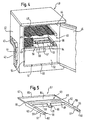
- FIG 1 is a simplified schematic representation Household freezer 10 shown with a heat-insulating housing 11 shown, which on its back one by a step-like recess Machine room 12 formed (see Figure 2) and which one Outer casing 13, a thermal insulation layer produced by foaming 13.1 and has a plastic inner lining 14.
- This is used for Lining a accessible via a heat insulating door 15 Freezer compartment 16.
- This is from a so-called wire tube evaporator 17th cooled, the evaporator levels 18 arranged one above the other at intervals, 19 and 20, of which the deepest within the freezer compartment 16 lying evaporator tier 20 immediately above the engine room 12 forming step-like recess is arranged.
- Freezer container is provided, which has a front wall 22 facing the door 15, one of these opposite rear wall 23, two side walls 24, one for Setting up the freezer container serving bottom wall 25 and a at least almost the area of the bottom wall 25 Has container opening 26.
- the frozen goods container is in its correct position Location within the freezer 16 with its rear wall 23 to close to Creation of the engine room 12 serving step-like return introduced.
- Defrosting tray 27 At its horizontal section is one Defrosting tray 27 set which z. B. in one piece Plastic injection molding is made.
- the condensation drip tray has one to the Contour of the horizontal section of the step-like recess Floor 28 two opposite side walls 29 and one Rear wall 30, which has the free end on which the rear wall of the Freezer compartment 16 covering portion of the inner panel 14 for the greatest possible avoidance of condensate leakage rests like a knife.
- the condensation water collecting tray 27 has on it Collection container 21 side facing one with respect to the height of the rear wall raised front wall 31, which is approximately in the center of its width Drain opening in the form of a condensation channel 32, the free Channel end 33 opens into the container opening 26.
- the Defrost water collecting tray 27 has one through the bottom 28 of which Side walls 29, bordered on the rear wall 30 and the front wall 31 thereof Collection space 34, the slope of which is aligned with the condensation channel 32, the raised front wall 31 as a storage wall for the Defrosting the evaporator levels 18 to 20 accruing melt water serves which is fed along the front wall 31 of the condensate channel 32.
- FIG. 3 shows a largely similar design to the freezer 10 Household freezer 40, with a heat-insulating housing 41 on it Back of a step-like recess to form a machine room 42 is provided.
- the heat-insulating housing 41 has one Outer lining 43, an inner lining 44 and one on its Machine room 42 opposite pivotally mounted front Door 45, through which a lined by the inner panel 44 Freezer compartment 46 is accessible.
- Evaporator level 48 is e.g. made in one piece from plastic injection molding Collection container 51 is provided. This is with a front wall 52 on the door side opposite rear wall 53, two each other opposite side walls 54 and a bottom wall 55 equipped. Compared to the bottom wall 55, the collecting container 51 has an im essentially the container opening 56 having the surface of the bottom wall 55 on.
- Defrost water collecting bowl 57 is provided, which two opposite each other arranged, forming the legs of the profile shell arms 58, the Length extends essentially over the length of the container opening 56.
- the Shell arms 58 are essentially gutter-like and have two opposite side walls 59 and one connecting them, door side arranged front wall 60, which together with a bottom 61 Define gutter bed 62, its slope executed towards engine room 42 is generated by the slope of the floor 61.
- the having the channel bed 62 Shell arms 58 are connected to one another by one of the two shell arms 58 U-profile connecting base connected, which as a condensate collecting section 63 serves.
- the condensation water collection section 63 has a height the rear wall 66 raises the executed front wall 68, which is approximately in the middle its width is provided with a condensation channel 69 serving as a drain opening, whose free channel end 70 opens inside the container opening 56.
- the Defrost channel 69 is that which accumulates in the defrost water collection section 63 Melt water fed, which for this purpose with its slope to Defrost channel 69 is executed and on which the shell arms 58 with are aligned with their slope.
- Defrost water collecting section 63 collecting defrost water serves the opposite of Rear wall 66 increases executed front wall 68 as a storage wall, on which the melt water located within the condensate collection space flows in and along which the melt water is then transferred into the condensation channel 69.
- a condensation drip tray would also be conceivable, which with its tray bottom also covers the container opening 26 and 56, respectively Shell bottom in the area of the container opening with serving as drain openings Breakthroughs should be provided while the outside of the container opening lying bottom areas of the condensation water collecting pan closed wall executed and should be aligned with their slope to the container opening.
Landscapes
- Engineering & Computer Science (AREA)
- Chemical & Material Sciences (AREA)
- Combustion & Propulsion (AREA)
- Physics & Mathematics (AREA)
- Mechanical Engineering (AREA)
- Thermal Sciences (AREA)
- General Engineering & Computer Science (AREA)
- Removal Of Water From Condensation And Defrosting (AREA)
Claims (8)
- Appareil frigorifique, par exemple surgélateur, combinaison de réfrigérateur et de surgélateur ou similaires, avec au moins une chambre de surgélation qui peut être fermée par une porte, qui est refroidie par des grilles d'évaporateur disposées les unes au-dessus des autres à distance mutuelle et qui est équipée d'au moins un récipient à produits surgelés pour la réception de produits surgelés, une coquille (27, 57) de reprise d'eau de dégivrage qui présente au moins une surface de reprise (28) qui permet de reprendre l'eau de fusion qui s'égoutte dans la zone, éloignée de la porte, des grilles d'évaporateur (28, 19, 20, 48, 49) et qui est dotée d'au moins une ouverture d'évacuation (32, 69) qui amène l'eau de fusion à un récipient de collecte (21, 51) disposé à l'intérieur de la chambre de surgélation (16, 46) et qui reprend au moins approximativement la région de la coquille (27, 57) de reprise d'eau de dégivrage située à l'extérieur de la surface de reprise (28, 64) étant disposée en dessous de la grille d'évaporateur (20, 40) disposée le plus bas dans la chambre de surgélation (16, 46).
- Appareil frigorifique selon la revendication 1, caractérisé en ce que la coquille (27, 57) de reprise d'eau de dégivrage est disposée dans la région proche située en dessous de la grille d'évaporateur (20, 48) située le plus bas dans la chambre de surgélation (16, 46).
- Appareil frigorifique selon l'une des revendications 1 ou 2, caractérisé en ce que la coquille (27, 57) de reprise d'eau de dégivrage présente une surface de reprise (28, 61, 64) qui, pour la reprise de l'eau de fusion, recouvre au moins très largement la région de surface de la chambre de surgélation (16, 46) qui est située à l'extérieur de l'ouverture (26, 56) du récipient de collecte (21, 51).
- Appareil frigorifique selon la revendication 3, caractérisé en ce que la coquille (57) de reprise d'eau de dégivrage est réalisée en forme de U, les bords du profil en U tournés vers le récipient de collecte (51) débouchant à l'intérieur de l'ouverture (56) du récipient de collecte (51).
- Appareil frigorifique selon la revendication 4, caractérisé en ce que la coquille (57) de reprise d'eau de dégivrage configurée comme profil en U présente sur ses ailes (58) une pente tournée vers sa base (63), et en ce que la base (63) est dotée de l'ouverture d'évacuation (69) qui débouche à l'intérieur de l'ouverture (56) du récipient de collecte (51).
- Appareil frigorifique selon la revendication 5, caractérisé en ce que la base (63) est dotée sur son côté situé en face de l'ouverture d'évacuation (69) d'un bord (67) réalisé en formé de lame qui repose de manière au moins très largement étanche au liquide sur le côté arrière de la chambre de surgélation (46).
- Appareil frigorifique selon la revendication 1 ou 6, caractérisé en ce que l'ouverture d'évacuation est configurée comme rigole (32, 69) d'eau de dégivrage dont l'extrémité libre (33, 70) débouche à l'intérieur de l'ouverture (26, 56) du récipient de collecte (21, 51).
- Appareil frigorifique selon l'une des revendications 1 à 7, caractérisé en ce que le récipient de collecte (21, 51) est configuré comme récipient à produits surgelés et est disposé en dessous de la grille d'évaporateur (20, 48) située le plus bas.
Applications Claiming Priority (2)
| Application Number | Priority Date | Filing Date | Title |
|---|---|---|---|
| DE19857846 | 1998-12-15 | ||
| DE19857846A DE19857846A1 (de) | 1998-12-15 | 1998-12-15 | Kältegerät |
Publications (2)
| Publication Number | Publication Date |
|---|---|
| EP1010958A1 EP1010958A1 (fr) | 2000-06-21 |
| EP1010958B1 true EP1010958B1 (fr) | 2003-06-11 |
Family
ID=7891162
Family Applications (1)
| Application Number | Title | Priority Date | Filing Date |
|---|---|---|---|
| EP99124024A Expired - Lifetime EP1010958B1 (fr) | 1998-12-15 | 1999-12-09 | Appareil frigorifique |
Country Status (2)
| Country | Link |
|---|---|
| EP (1) | EP1010958B1 (fr) |
| DE (2) | DE19857846A1 (fr) |
Families Citing this family (3)
| Publication number | Priority date | Publication date | Assignee | Title |
|---|---|---|---|---|
| ES2182653B1 (es) * | 2000-09-04 | 2004-06-01 | Bsh Fabricacion, S.A. | Frigorifico. |
| DE10205647C1 (de) * | 2002-02-12 | 2003-07-03 | Rittal Gmbh & Co Kg | Kondensat-Auffangwanne für ein Kühlgerät |
| DE102011004591A1 (de) * | 2011-02-23 | 2012-08-23 | BSH Bosch und Siemens Hausgeräte GmbH | Kältegerät mit Verdunstungsschale |
Family Cites Families (5)
| Publication number | Priority date | Publication date | Assignee | Title |
|---|---|---|---|---|
| GB679093A (en) * | 1950-04-11 | 1952-09-10 | British Thomson Houston Co Ltd | Improvements in and relating to drip trays for refrigerators |
| FR1131085A (fr) * | 1955-02-23 | 1957-02-15 | Matfroid | Perfectionnement aux armoires frigorifiques |
| JPS623659Y2 (fr) * | 1981-01-19 | 1987-01-27 | ||
| DE8409125U1 (de) * | 1984-03-24 | 1985-07-18 | Licentia Patent-Verwaltungs-Gmbh, 6000 Frankfurt | Kühlgerät mit einer Ableitvorrichtung für Wasser |
| EP0272761A3 (fr) * | 1986-12-24 | 1990-01-10 | I.R.E. Industrie Riunite Eurodomestici S.p.A. | Congélateur vertical avec accumulation sélective de givre |
-
1998
- 1998-12-15 DE DE19857846A patent/DE19857846A1/de not_active Withdrawn
-
1999
- 1999-12-09 DE DE59905921T patent/DE59905921D1/de not_active Expired - Fee Related
- 1999-12-09 EP EP99124024A patent/EP1010958B1/fr not_active Expired - Lifetime
Also Published As
| Publication number | Publication date |
|---|---|
| EP1010958A1 (fr) | 2000-06-21 |
| DE59905921D1 (de) | 2003-07-17 |
| DE19857846A1 (de) | 2000-06-21 |
Similar Documents
| Publication | Publication Date | Title |
|---|---|---|
| DE10145140A1 (de) | Gehäuse für ein Kältegerät | |
| EP1857750B1 (fr) | Dispositif frigorifique avec préparateur de glace | |
| WO2011131438A2 (fr) | Vantail de porte, procédé de fabrication d'un vantail de porte et appareil frigorifique équipé d'un vantail de porte | |
| DE8608881U1 (de) | Haushaltskühl- oder Gefriergerät für Einbauküchen | |
| EP2612085A2 (fr) | Appareil de froid, en particulier appareil de froid électroménager | |
| EP1010958B1 (fr) | Appareil frigorifique | |
| EP2522937A2 (fr) | Dispositif de vaporisation pour un appareil frigorifique encastrable ainsi qu'appareil frigorifique encastrable et procédé d'encastrement d'un appareil frigorifique encastrable | |
| WO2012146581A2 (fr) | Contenant pour produits réfrigérés et appareil de froid comportant un contenant pour produits réfrigérés | |
| EP2612086A2 (fr) | Appareil frigorifique, notamment appareil frigorifique ménager | |
| WO2012022581A1 (fr) | Réfrigérateur comportant un rail de support pour une tablette | |
| EP0611929B1 (fr) | Appareil de refroidissement ou de congélation avec une enceinte isolée thermiquement | |
| EP1535007A1 (fr) | Appareil frigorifique avec interieur compartimente | |
| DE202018004467U1 (de) | Kältegerät mit Einbauteil | |
| EP2612087B1 (fr) | Appareil de froid, en particulier réfrigérateur domestique | |
| DE102016224389A1 (de) | No-Frost-Haushaltskältegerät mit zur Rückwand dichtender Trennplatte | |
| DE102007017011A1 (de) | Kühl- und/oder Gefriergerät | |
| EP2458307B1 (fr) | Appareil de refroidissement doté d'un dispositif goutte à goutte de collecte et d'un dispositif de déviation | |
| DE952716C (de) | Kuehlschrank | |
| DE19917974C2 (de) | Kühl- und/oder Gefriergerät mit einem im Innenraum angeordneten kältegenerierenden Bauteil | |
| DE102018122904A1 (de) | Gefriertruhe, insbesondere für Eiscreme-Produkte | |
| EP1284399A2 (fr) | Appareil frigorifique | |
| DE19633972A1 (de) | Tür für ein Kältegerät | |
| DE1601932A1 (de) | Schublade fuer Kuehlmoebel,vorzugsweise fuer Haushaltkuehlschraenke | |
| DE8133007U1 (de) | Gefriergeraet, insbesondere gefrierschrank oder dergleichen | |
| DE1992546U (de) | Kuehlschrank. |
Legal Events
| Date | Code | Title | Description |
|---|---|---|---|
| PUAI | Public reference made under article 153(3) epc to a published international application that has entered the european phase |
Free format text: ORIGINAL CODE: 0009012 |
|
| AK | Designated contracting states |
Kind code of ref document: A1 Designated state(s): DE DK ES FR GB IT |
|
| AX | Request for extension of the european patent |
Free format text: AL;LT;LV;MK;RO;SI |
|
| 17P | Request for examination filed |
Effective date: 20001124 |
|
| AKX | Designation fees paid |
Free format text: DE DK ES FR GB IT |
|
| AXX | Extension fees paid |
Free format text: SI PAYMENT 20001124 |
|
| GRAH | Despatch of communication of intention to grant a patent |
Free format text: ORIGINAL CODE: EPIDOS IGRA |
|
| GRAH | Despatch of communication of intention to grant a patent |
Free format text: ORIGINAL CODE: EPIDOS IGRA |
|
| GRAA | (expected) grant |
Free format text: ORIGINAL CODE: 0009210 |
|
| AK | Designated contracting states |
Designated state(s): DE DK ES FR GB IT |
|
| AX | Request for extension of the european patent |
Extension state: SI |
|
| PG25 | Lapsed in a contracting state [announced via postgrant information from national office to epo] |
Ref country code: IT Free format text: LAPSE BECAUSE OF FAILURE TO SUBMIT A TRANSLATION OF THE DESCRIPTION OR TO PAY THE FEE WITHIN THE PRE;WARNING: LAPSES OF ITALIAN PATENTS WITH EFFECTIVE DATE BEFORE 2007 MAY HAVE OCCURRED AT ANY TIME BEFORE 2007. THE CORRECT EFFECTIVE DATE MAY BE DIFFERENT FROM THE ONE RECORDED.SCRIBED TIME-LIMIT Effective date: 20030611 Ref country code: GB Free format text: LAPSE BECAUSE OF FAILURE TO SUBMIT A TRANSLATION OF THE DESCRIPTION OR TO PAY THE FEE WITHIN THE PRESCRIBED TIME-LIMIT Effective date: 20030611 Ref country code: FR Free format text: LAPSE BECAUSE OF FAILURE TO SUBMIT A TRANSLATION OF THE DESCRIPTION OR TO PAY THE FEE WITHIN THE PRESCRIBED TIME-LIMIT Effective date: 20030611 |
|
| REG | Reference to a national code |
Ref country code: GB Ref legal event code: FG4D Free format text: NOT ENGLISH |
|
| REF | Corresponds to: |
Ref document number: 59905921 Country of ref document: DE Date of ref document: 20030717 Kind code of ref document: P |
|
| PG25 | Lapsed in a contracting state [announced via postgrant information from national office to epo] |
Ref country code: DK Free format text: LAPSE BECAUSE OF FAILURE TO SUBMIT A TRANSLATION OF THE DESCRIPTION OR TO PAY THE FEE WITHIN THE PRESCRIBED TIME-LIMIT Effective date: 20030911 |
|
| PG25 | Lapsed in a contracting state [announced via postgrant information from national office to epo] |
Ref country code: ES Free format text: LAPSE BECAUSE OF FAILURE TO SUBMIT A TRANSLATION OF THE DESCRIPTION OR TO PAY THE FEE WITHIN THE PRESCRIBED TIME-LIMIT Effective date: 20030922 |
|
| GBV | Gb: ep patent (uk) treated as always having been void in accordance with gb section 77(7)/1977 [no translation filed] |
Effective date: 20030611 |
|
| RAP2 | Party data changed (patent owner data changed or rights of a patent transferred) |
Owner name: BSH BOSCH UND SIEMENS HAUSGERAETE GMBH |
|
| PLBE | No opposition filed within time limit |
Free format text: ORIGINAL CODE: 0009261 |
|
| STAA | Information on the status of an ep patent application or granted ep patent |
Free format text: STATUS: NO OPPOSITION FILED WITHIN TIME LIMIT |
|
| 26N | No opposition filed |
Effective date: 20040312 |
|
| EN | Fr: translation not filed | ||
| PG25 | Lapsed in a contracting state [announced via postgrant information from national office to epo] |
Ref country code: DE Free format text: LAPSE BECAUSE OF NON-PAYMENT OF DUE FEES Effective date: 20040701 |