EP2612087B1 - Appareil de froid, en particulier réfrigérateur domestique - Google Patents
Appareil de froid, en particulier réfrigérateur domestique Download PDFInfo
- Publication number
- EP2612087B1 EP2612087B1 EP11746537.7A EP11746537A EP2612087B1 EP 2612087 B1 EP2612087 B1 EP 2612087B1 EP 11746537 A EP11746537 A EP 11746537A EP 2612087 B1 EP2612087 B1 EP 2612087B1
- Authority
- EP
- European Patent Office
- Prior art keywords
- gutter
- condensation
- refrigerator
- wall
- refrigerator according
- Prior art date
- Legal status (The legal status is an assumption and is not a legal conclusion. Google has not performed a legal analysis and makes no representation as to the accuracy of the status listed.)
- Not-in-force
Links
- 230000005494 condensation Effects 0.000 claims description 69
- 238000009833 condensation Methods 0.000 claims description 69
- 238000001704 evaporation Methods 0.000 claims description 13
- 238000001816 cooling Methods 0.000 claims description 7
- 239000000463 material Substances 0.000 claims description 5
- 238000009434 installation Methods 0.000 claims description 3
- 239000002184 metal Substances 0.000 claims 2
- 239000002937 thermal insulation foam Substances 0.000 claims 1
- XLYOFNOQVPJJNP-UHFFFAOYSA-N water Substances O XLYOFNOQVPJJNP-UHFFFAOYSA-N 0.000 description 23
- 230000008020 evaporation Effects 0.000 description 12
- 238000005057 refrigeration Methods 0.000 description 9
- 238000010257 thawing Methods 0.000 description 6
- 239000003507 refrigerant Substances 0.000 description 4
- 238000004519 manufacturing process Methods 0.000 description 2
- 239000002918 waste heat Substances 0.000 description 2
- GRNHLFULJDXJKR-UHFFFAOYSA-N 3-(2-sulfanylethyl)-1h-quinazoline-2,4-dione Chemical compound C1=CC=C2C(=O)N(CCS)C(=O)NC2=C1 GRNHLFULJDXJKR-UHFFFAOYSA-N 0.000 description 1
- 238000010276 construction Methods 0.000 description 1
- 230000009977 dual effect Effects 0.000 description 1
- 238000005187 foaming Methods 0.000 description 1
- 238000000034 method Methods 0.000 description 1
- 230000001737 promoting effect Effects 0.000 description 1
- 238000007493 shaping process Methods 0.000 description 1
- 238000003856 thermoforming Methods 0.000 description 1
Images

Classifications
-
- F—MECHANICAL ENGINEERING; LIGHTING; HEATING; WEAPONS; BLASTING
- F25—REFRIGERATION OR COOLING; COMBINED HEATING AND REFRIGERATION SYSTEMS; HEAT PUMP SYSTEMS; MANUFACTURE OR STORAGE OF ICE; LIQUEFACTION SOLIDIFICATION OF GASES
- F25D—REFRIGERATORS; COLD ROOMS; ICE-BOXES; COOLING OR FREEZING APPARATUS NOT OTHERWISE PROVIDED FOR
- F25D21/00—Defrosting; Preventing frosting; Removing condensed or defrost water
- F25D21/14—Collecting or removing condensed and defrost water; Drip trays
-
- F—MECHANICAL ENGINEERING; LIGHTING; HEATING; WEAPONS; BLASTING
- F25—REFRIGERATION OR COOLING; COMBINED HEATING AND REFRIGERATION SYSTEMS; HEAT PUMP SYSTEMS; MANUFACTURE OR STORAGE OF ICE; LIQUEFACTION SOLIDIFICATION OF GASES
- F25D—REFRIGERATORS; COLD ROOMS; ICE-BOXES; COOLING OR FREEZING APPARATUS NOT OTHERWISE PROVIDED FOR
- F25D2321/00—Details or arrangements for defrosting; Preventing frosting; Removing condensed or defrost water, not provided for in other groups of this subclass
- F25D2321/14—Collecting condense or defrost water; Removing condense or defrost water
- F25D2321/144—Collecting condense or defrost water; Removing condense or defrost water characterised by the construction of drip water collection pans
- F25D2321/1442—Collecting condense or defrost water; Removing condense or defrost water characterised by the construction of drip water collection pans outside a refrigerator
-
- F—MECHANICAL ENGINEERING; LIGHTING; HEATING; WEAPONS; BLASTING
- F25—REFRIGERATION OR COOLING; COMBINED HEATING AND REFRIGERATION SYSTEMS; HEAT PUMP SYSTEMS; MANUFACTURE OR STORAGE OF ICE; LIQUEFACTION SOLIDIFICATION OF GASES
- F25D—REFRIGERATORS; COLD ROOMS; ICE-BOXES; COOLING OR FREEZING APPARATUS NOT OTHERWISE PROVIDED FOR
- F25D2321/00—Details or arrangements for defrosting; Preventing frosting; Removing condensed or defrost water, not provided for in other groups of this subclass
- F25D2321/14—Collecting condense or defrost water; Removing condense or defrost water
- F25D2321/145—Collecting condense or defrost water; Removing condense or defrost water characterised by multiple collecting pans
-
- F—MECHANICAL ENGINEERING; LIGHTING; HEATING; WEAPONS; BLASTING
- F25—REFRIGERATION OR COOLING; COMBINED HEATING AND REFRIGERATION SYSTEMS; HEAT PUMP SYSTEMS; MANUFACTURE OR STORAGE OF ICE; LIQUEFACTION SOLIDIFICATION OF GASES
- F25D—REFRIGERATORS; COLD ROOMS; ICE-BOXES; COOLING OR FREEZING APPARATUS NOT OTHERWISE PROVIDED FOR
- F25D2400/00—General features of, or devices for refrigerators, cold rooms, ice-boxes, or for cooling or freezing apparatus not covered by any other subclass
- F25D2400/32—Removal, transportation or shipping of refrigerating devices from one location to another
-
- F—MECHANICAL ENGINEERING; LIGHTING; HEATING; WEAPONS; BLASTING
- F25—REFRIGERATION OR COOLING; COMBINED HEATING AND REFRIGERATION SYSTEMS; HEAT PUMP SYSTEMS; MANUFACTURE OR STORAGE OF ICE; LIQUEFACTION SOLIDIFICATION OF GASES
- F25D—REFRIGERATORS; COLD ROOMS; ICE-BOXES; COOLING OR FREEZING APPARATUS NOT OTHERWISE PROVIDED FOR
- F25D2500/00—Problems to be solved
- F25D2500/02—Geometry problems
Definitions
- the invention relates to a refrigerator according to the preamble of claim 1.
- a refrigeration device is in particular a household refrigeration appliance understood, ie a refrigerator that is used for household management in households or possibly in the catering sector, and in particular serves to store food and / or drinks in household quantities at certain temperatures, such as a refrigerator, a Freezer, a fridge-freezer or a wine storage cabinet.
- the condensation water formed in the cold room of a refrigerator is usually conducted by means of a condensed water line from the refrigerator to the outer rear of the device and collected there in an evaporation tray.
- the collected condensation water can evaporate into the environment using the waste heat from the compressor and / or the condenser of the refrigerant circuit.
- cascade-like condensation water channels arranged one above the other can be provided on the rear side of the unit, which are fluidically interconnected.
- Each of the in the DE 6 810 043 U1 each has one, in the device side direction facing frontal overflow edge, so that excess condensation can drain from an upper dewatering channel laterally into the underlying condensation channel.
- the lateral overflow edges are each provided alternately on the left or right front side, while at the horizontal opposite end of the respective condensation gutter is closed watertight.
- a meandering flow path of the condensation water with changing flow directions per discharge channel is predetermined, resulting in an overall complex geometry of the evaporation arrangement.
- the problem arises that at the respective watertight closed sides of the defrost water channels create dead spaces in which the condensate collects without draining possibility.
- AN 1997-488281, - & RU 2 077 686 C1 (MUROMSK MECH ENG WKS STOCK CO) April 20, 1997 (1997-04-20 ) discloses a refrigerator with a series of superimposed condensation channels for collecting and evaporation of itself in the refrigerator of the refrigeratorumbledem condensation water, of which at least one condensation gutter is closed at both end faces and extending in trough longitudinal direction, from the refrigerator outwardly projecting gutter wall, wherein the gutter wall of the condensation gutter in the upper edge has a, to a height offset set back overflow edge.
- the object of the invention is to provide a refrigeration device, in particular domestic refrigeration appliance, which has a geometrically simple evaporation arrangement in which the condensation can flow down even when the appliance is tilted.
- the refrigeration device has a series of superimposed condensation water channels, in which the condensate can be collected and evaporated. At least one of these Tauwasserrinnen is closed at both end faces and has a groove in the longitudinal direction extending from the refrigerator outwardly projecting gutter wall. According to the invention, this gutter wall extending in the groove longitudinal direction has a overflow edge which is set back by a vertical offset in the upper edge course. The condensation water can thus flow down over this deeper-seated overflow edge. Depending on the expected amount of condensation water, the length of this overflow edge and the height offset can be varied. It is preferable if the Overflow edge in the gutter longitudinal direction extends substantially over the entire length of the condensation gutter.
- the condensation gutters can usually be arranged on the rear side of the appliance. There, the collected condensation water can evaporate into the environment using the waste heat from the compressor / condenser.
- the condensation gutter can be reinforced at the lateral corner regions by raised Wandendabitese.
- the Wandendabitese are respectively provided on the front side at the two ends of the channel wall and can pass over a gradation in the centrally provided overflow edge.
- the two lateral, raised Wandendabitese the gutter wall can converge with the end faces at the corners. Both the end faces and the Wandendabitese may extend beyond the already mentioned height offset to further increase the component stiffness of the overflow edge.
- the defrosting channels can be integrally formed on a base body, in particular a plate arranged at an angle, in the same material and / or in one piece.
- the defrosting channels can be designed here in conjunction with the base body as a plastic part.
- the rear wall projecting gutter wall together with the plate-shaped body limit a condensation water collection space.
- the gutter wall may be formed on the outside with an inclined flank, wherein the limited Tauwassersammelraum limited by the channel wall is wedge-shaped in profile. Excess condensation can run along the drainage flank. The running edge of the channel wall can pass over a horizontal run-off edge into the plate-shaped base body. Therefore, the overflowing condensation water first flows over the drainage flank in the direction of the vertically lower drainage edge and then further into the underlying drainage channel. So that the dripping condensation water is completely absorbed by this underlying gully is it is advantageous if the lower condensation gutter laterally surmounted the outflow edge of the upper condensation gutter by an oversize.
- opposite end faces of the condensation gutter can diverge in an inclined position upwards.
- the evaporation arrangement embodied with the above-mentioned geometrical features makes possible a mirror-symmetrical design, which is advantageous with regard to a component stiffness as well as to a simple shaping.
- the axis of symmetry here corresponds to a central axis of the superimposed condensate channels, which extends in the vertical direction.
- the above-described component geometry makes it possible to carry out the same identity as the gutters.
- the plate-shaped body can not only carry the condensation water inside, but also be executed in a dual function as an outer wall part, which defines a cavity filled with planteolierschaum together with an inner container defining the cooling space.
- the plate-shaped body can also be used as a supporting structural element of the refrigerator body. Such structural elements may extend as traverses between the lateral outer walls of the refrigerator and connect them together. In this way, the device body can be sufficiently stiffened before the foaming process.
- Fig. 1 is shown in a perspective partial view of the rear machine room 1 of a refrigeration appliance.
- the engine room 1 is limited as a return between the two lateral outer walls 3 of the refrigerator.
- a in the Fig. 1 indicated compressor 5 of the refrigerant circuit arranged.
- the top of the engine room 1 is characterized by an only in the Fig. 4 shown top wall 7 limited upward.
- the horizontally extending top wall 7 is in a manner not shown here in a vertical, that is vertically arranged plate 9 over.
- the plate 9 is formed as a supporting structural part, which is screwed in each case with rear attachment flanges 11 of the outer walls 3 opposite in the device side direction x.
- a condensation water outlet 14 is formed approximately in the center of the top of the plate 9, the fluidically with a only in the Fig. 4 shown condensation pipe 15 is connected.
- the refrigerant circuit of the refrigerator has in addition to the compressor 5 further components, namely condenser, expansion element and an evaporator, which thermally with the in the Fig. 4 indicated refrigerator 16 is coupled. These components, like other refrigerant circuit components, are not shown in the figures for reasons of clarity.
- the condenser is mounted in a conventional manner on the rear of the device in a vertical plane and slightly spaced from the vertical wall element 13 of the refrigerator. The condenser extends in a vertical plane to approximately at the height of the top wall 7 of the mounting space. 1
- the designed as a supporting structural element plate 9 is made of a readily moldable plastic material.
- the plastic plate 9 also carries on its in the depth direction y backward side facing a series of superimposed condensation gutters 17, which are integrally formed integrally with the plate-shaped base body 9. Due to the large number of condensation gutters 17 results in a, the evaporation promoting large water surface.
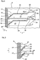
- the drainage channels 17 are all constructed identical. Thus, according to the enlarged partial view of the Fig. 2 Each of the channels 17 has a channel wall 19 projecting rearwardly in the depth direction y, which is formed in an oblique position over an angle ⁇ to the plate-shaped basic body 9.
- the channel wall 19 forms, together with the plate-shaped base body 9 in a wedge-shaped wedge-shaped collecting chamber, in which the condensation is maintained.
- the gutter wall 19 of each condensation gutter 17 extends in each case in the device side direction x over almost the entire width of the plate-shaped base body 9.
- the condensation gutters 17 are in a vertical installation position of the refrigerator horizontally, that is arranged without flow gradient for the condensate held therein.
- each dew channel 17 in the upper edge curve has a, by a height offset ⁇ h down recessed overflow edge 23.
- the recessed overflow edge 23 extends in the channel longitudinal direction x substantially over the entire length of each drainage channel 17.
- laterally raised end sections 25 are provided on both sides of the channel wall 19.
- the overflow edge 23 passes laterally at a gradation in the raised end portions 25.
- the raised end portions 25 protrude together with the end faces 21, the overflow edge 23 by the aforementioned height offset .DELTA.h.
- the inclined by the angle ⁇ channel wall 19 forms according to the Fig. 2 on the outside, a drain flank 27, can run to the overflowing condensate to the underlying condensation channel 17.
- the running edge 27 merges with a horizontal run-off edge 29 in the plate-shaped base body 9, which in the Fig. 2 extends with a length I in the device side direction x.
- a wedge-shaped collecting chamber which is wedge-shaped in profile and laterally closed by similarly shaped triangular end faces 21 results.
- the so-shaped end faces 21 are not vertically raised, but extend the opposite end faces 21 of the condensation gutter 19 vertically upwards apart. Accordingly, the cross-sectional area of the condensation water collecting space widens upward in both the depth direction y and in the apparatus side direction x.
- Fig. 2 only the right side of the condensate channels 19 is shown.
- the left side of the condensation water inside 19 is carried out in mirror image, in relation to a in the Fig. 1 indicated vertical center axis M of the plate-shaped base body 9.
- all the defrosting channels 19 of the base body 9 are geometrically identical. This allows the defrosting channels 19 in the, in the FIGS. 2 and 3 shown nested construction are arranged one above the other in a cascade.
- the length I of the outflow edge 29 of the in the Fig. 2 shown upper drainage channel 17 is due to the above geometric conditions in device side direction x executed lower than the upwardly open cross-section of the condensate collecting space of the underlying condensation channel 17.
- the end faces 21 of each lower condensate channel 17 protrude therefore in the device side direction x each an oversize a on Therefore, even if in extreme situations, such as during transport, by an extreme inclination of the refrigerator, the condensation also runs over the end faces 21, it is therefore ensured that the overflowing condensation completely run in the below-arranged condensation channel 17 can.
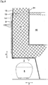
- the plate-shaped base body 9 forms together with the vertical wall element 13 and the top wall 7 each outer wall parts, which define a, the cooling space 16 delimiting inner container 31, filled with réelleisolierschaum 33 cavity.
- the inner container 31 is made in a known manner by thermoforming of plastic.
- the limited cooling space 16 is according to the Fig. 4 connected via the dew point line 15 shown in dashed lines with the integrated in the plate-shaped base body 9 condensation water outlet 14, whereby the condensation water formed in the cooling chamber 16 via the condensation water outlet 14th can first drip on the topmost gutter 17 of the plate-shaped base body 9.
Landscapes
- Engineering & Computer Science (AREA)
- Chemical & Material Sciences (AREA)
- Combustion & Propulsion (AREA)
- Physics & Mathematics (AREA)
- Mechanical Engineering (AREA)
- Thermal Sciences (AREA)
- General Engineering & Computer Science (AREA)
- Removal Of Water From Condensation And Defrosting (AREA)
Claims (11)
- Appareil frigorifique, notamment appareil frigorifique à usage domestique, comprenant une série de gouttières d'eau de condensation (17) disposées les unes au-dessus des autres, destinées à collecter et faire évaporer l'eau de condensation se formant dans l'espace de réfrigération (16) de l'appareil frigorifique, dont au moins une gouttière d'eau de condensation (17) est fermée sur les deux côtés frontaux (21) et dont une présente une paroi de gouttière (19) s'étendant en direction longitudinale (x) de la gouttière, faisant saillie de l'appareil frigorifique vers l'extérieur, la paroi de gouttière (19) de la gouttière d'eau de condensation (17) présentant dans l'allure de bord supérieur un bord de débordement (23) décalé d'un décalage en hauteur (Δh), caractérisé en ce que les côtés frontaux (21) de la gouttière d'eau de condensation (17), opposés l'un à l'autre en direction longitudinale (x) de la gouttière, divergent vers le haut en position oblique dans un angle (β), et en ce que dans au moins deux gouttières d'eau de condensation (17) disposées l'une au-dessus de l'autre, la gouttière inférieure (17) d'eau de condensation dépasse un bord d'évacuation (29) de la gouttière supérieure (17) d'eau de condensation d'un surdimensionnement (a) dans la direction longitudinale (x) de la gouttière.
- Appareil frigorifique selon la revendication 1, caractérisé en ce que le bord de débordement (23) s'étend dans la direction longitudinale (x) de la gouttière essentiellement sur toute la longueur de la gouttière d'eau de condensation (17).
- Appareil frigorifique selon la revendication 1 ou 2, caractérisé en ce que le bord de débordement (23) est décalé du décalage en hauteur (Δh) du bord supérieur des côtés frontaux (21) de la gouttière d'eau de condensation (17).
- Appareil frigorifique selon l'une quelconque des revendications 1 à 3, caractérisé en ce que dans l'allure du bord supérieur de la paroi de gouttière (19), le bord de débordement (23), en direction longitudinale (x) de la gouttière, se transforme, par l'intermédiaire d'un échelonnement, en sections de parois terminales (25) étirées vers le haut.
- Appareil frigorifique selon la revendication 4, caractérisé en ce que les sections de parois terminales (25) étirées vers le haut convergent avec les côtés frontaux (21) de la paroi de gouttière (19) dans des zones en coin (24).
- Appareil frigorifique selon l'une quelconque des revendications précédentes, caractérisé en ce que les gouttières d'eau de condensation (17) sont formées sur un corps de base (9), notamment sur une plaque disposée verticalement, en matière homogène et/ou d'une seule pièce, notamment la paroi de gouttière (19) délimitant avec la plaque (9) un espace collecteur d'eau de condensation.
- Appareil frigorifique selon la revendication 6, caractérisé en ce que la paroi de gouttière (19) est formée sur le corps de base (9) en position oblique dans un angle (α), et/ou en ce que la paroi de gouttière (19) forme côté extérieur en profil un flanc d'évacuation (27) oblique, le long duquel l'eau de condensation débordant est évacuée, et en ce que le flanc d'évacuation (27) se transforme en corps de base (9) sur un bord d'évacuation (29).
- Appareil frigorifique selon l'une quelconque des revendications précédentes, caractérisé en ce que la gouttière d'eau de condensation (17), par rapport à un axe médian (M), est réalisée de manière symétrique par réflexion et/ou en ce que les gouttières d'eau de condensation (17) sont réalisées avec géométrie identique.
- Appareil frigorifique selon l'une quelconque des revendications précédentes, caractérisé en ce que la gouttière d'eau de condensation (17), en position de montage d'aplomb de l'appareil frigorifique, est disposée dans un plan horizontal, c'est-à-dire sans pente d'écoulement pour l'eau de condensation.
- Appareil frigorifique selon l'une quelconque des revendications 6 à 9, caractérisé en ce que le corps de base (9) est une partie de paroi extérieure du corps de l'appareil frigorifique, qui, avec un réservoir intérieur (31) définissant l'espace de réfrigération (16), délimite un espace creux rempli de mousse thermo-isolante (33).
- Appareil frigorifique selon l'une quelconque des revendications 6 à 10, caractérisé en ce que le corps de base (9), en tant qu'un élément de renforcement, relie entre elles les parois extérieures (3) latérales de l'appareil frigorifique.
Applications Claiming Priority (2)
| Application Number | Priority Date | Filing Date | Title |
|---|---|---|---|
| DE201010040252 DE102010040252A1 (de) | 2010-09-03 | 2010-09-03 | Kältegerät, insbesondere Haushaltskältegerät |
| PCT/EP2011/064265 WO2012028474A2 (fr) | 2010-09-03 | 2011-08-19 | Appareil de froid, en particulier réfrigérateur domestique |
Publications (2)
| Publication Number | Publication Date |
|---|---|
| EP2612087A2 EP2612087A2 (fr) | 2013-07-10 |
| EP2612087B1 true EP2612087B1 (fr) | 2017-03-15 |
Family
ID=44503860
Family Applications (1)
| Application Number | Title | Priority Date | Filing Date |
|---|---|---|---|
| EP11746537.7A Not-in-force EP2612087B1 (fr) | 2010-09-03 | 2011-08-19 | Appareil de froid, en particulier réfrigérateur domestique |
Country Status (5)
| Country | Link |
|---|---|
| EP (1) | EP2612087B1 (fr) |
| CN (1) | CN103261821B (fr) |
| DE (1) | DE102010040252A1 (fr) |
| RU (1) | RU2537536C2 (fr) |
| WO (1) | WO2012028474A2 (fr) |
Families Citing this family (2)
| Publication number | Priority date | Publication date | Assignee | Title |
|---|---|---|---|---|
| CN104329873B (zh) * | 2014-03-28 | 2017-01-25 | 海尔集团公司 | 一种冰箱及其接水盒 |
| CN110887317A (zh) * | 2018-09-07 | 2020-03-17 | 青岛海尔特种电冰柜有限公司 | 一种接水盒及冷藏冷冻设备 |
Family Cites Families (10)
| Publication number | Priority date | Publication date | Assignee | Title |
|---|---|---|---|---|
| GB720985A (en) * | 1952-06-05 | 1954-12-29 | Gen Electric | Improvements in and relating to refrigerators |
| DE6810043U (de) | 1968-12-05 | 1969-05-08 | Licentia Gmbh | Einrichtung zur verdunstung des abtauwassers in kuehlschraenken |
| GB1460450A (en) * | 1973-03-01 | 1977-01-06 | Barker Co Leeds Ltd George | Vapour cycle refrigeration systems |
| US4766737A (en) * | 1983-05-09 | 1988-08-30 | Displaymor Manufacturing Company | Refrigerated storage and display device with multiple pan dissipator array |
| GB8512339D0 (en) * | 1985-05-15 | 1985-06-19 | Hotpoint Ltd | Refrigerators |
| JP2552535B2 (ja) * | 1988-06-29 | 1996-11-13 | 三洋電機株式会社 | 天吊型冷却装置 |
| CN2095381U (zh) * | 1991-09-05 | 1992-02-05 | 天津商学院制冷技术研究所 | 空气冷却器防溅水装置 |
| RU2077686C1 (ru) * | 1995-02-15 | 1997-04-20 | Акционерное общество "Муромский машиностроительный завод" | Устройство для отвода талой воды при оттайке испарителя бытового холодильного прибора |
| JPH1019450A (ja) * | 1996-06-28 | 1998-01-23 | Sanyo Electric Co Ltd | 冷却貯蔵庫 |
| JP2007240095A (ja) * | 2006-03-10 | 2007-09-20 | Fukushima Industries Corp | 解凍機 |
-
2010
- 2010-09-03 DE DE201010040252 patent/DE102010040252A1/de not_active Withdrawn
-
2011
- 2011-08-19 WO PCT/EP2011/064265 patent/WO2012028474A2/fr not_active Ceased
- 2011-08-19 EP EP11746537.7A patent/EP2612087B1/fr not_active Not-in-force
- 2011-08-19 RU RU2013111686/13A patent/RU2537536C2/ru active
- 2011-08-19 CN CN201180042515.2A patent/CN103261821B/zh not_active Expired - Fee Related
Non-Patent Citations (1)
| Title |
|---|
| None * |
Also Published As
| Publication number | Publication date |
|---|---|
| RU2537536C2 (ru) | 2015-01-10 |
| CN103261821A (zh) | 2013-08-21 |
| WO2012028474A3 (fr) | 2012-07-26 |
| CN103261821B (zh) | 2015-05-20 |
| WO2012028474A2 (fr) | 2012-03-08 |
| RU2013111686A (ru) | 2014-10-10 |
| EP2612087A2 (fr) | 2013-07-10 |
| DE102010040252A1 (de) | 2012-03-08 |
Similar Documents
| Publication | Publication Date | Title |
|---|---|---|
| WO2011026749A2 (fr) | Appareil de froid pourvu d'un bac à légumes | |
| EP2561292B1 (fr) | Vantail de porte, procédé de fabrication d'un vantail de porte et appareil frigorifique équipé d'un vantail de porte | |
| EP3194869B1 (fr) | Appareil de réfrigération pourvu d'une pluralité de compartiments de stockage | |
| DE202015009862U1 (de) | Kühlschrank | |
| EP2678623B1 (fr) | Appareil frigorifique comportant une coquille d'évaporation | |
| EP1832199A2 (fr) | Meuble destiné à la réception de nourriture et/ou de produits hygiéniques | |
| WO2012028469A2 (fr) | Appareil de froid, en particulier appareil de froid électroménager | |
| EP2612087B1 (fr) | Appareil de froid, en particulier réfrigérateur domestique | |
| EP2612086A2 (fr) | Appareil frigorifique, notamment appareil frigorifique ménager | |
| EP2414747A2 (fr) | Appareil frigorifique à usage domestique, avec une platine d'évaporation comportant une tôle chicane, et procédé de fabrication d'une telle platine d'évaporation avec tôle chicane | |
| WO2012175367A2 (fr) | Appareil frigorifique à canal de circulation d'air | |
| EP2372277A2 (fr) | Appareil de refroidissement doté d'un évaporateur d'eau de décongélation | |
| DE102009028781A1 (de) | Kältegerät mit Tauwasser-Auffangrinne | |
| EP1934541B1 (fr) | Plateau de stockage pour un appareil de refrigeration | |
| WO2012113625A1 (fr) | Appareil frigorifique comportant un condenseur de paroi arrière | |
| WO2004015341A1 (fr) | Appareil frigorifique avec interieur compartimente | |
| EP2419687B1 (fr) | Appareil frigorifique sans givre | |
| EP1010958B1 (fr) | Appareil frigorifique | |
| DE102008063391A1 (de) | Kältegerät mit Fachboden | |
| EP2458307B1 (fr) | Appareil de refroidissement doté d'un dispositif goutte à goutte de collecte et d'un dispositif de déviation | |
| DE102019214531A1 (de) | Kältegerät mit ToS-Verdampfer | |
| DE102018122904A1 (de) | Gefriertruhe, insbesondere für Eiscreme-Produkte | |
| EP3655714B1 (fr) | Réfrigérateur à évaporateur à écoulement de contournement | |
| EP3023726A1 (fr) | Appareil frigorifique comprenant un évaporateur à ventilation forcée | |
| DE2134539A1 (de) | Kuehlmoebel, insbesondere kuehlschrank |
Legal Events
| Date | Code | Title | Description |
|---|---|---|---|
| PUAI | Public reference made under article 153(3) epc to a published international application that has entered the european phase |
Free format text: ORIGINAL CODE: 0009012 |
|
| 17P | Request for examination filed |
Effective date: 20130403 |
|
| AK | Designated contracting states |
Kind code of ref document: A2 Designated state(s): AL AT BE BG CH CY CZ DE DK EE ES FI FR GB GR HR HU IE IS IT LI LT LU LV MC MK MT NL NO PL PT RO RS SE SI SK SM TR |
|
| DAX | Request for extension of the european patent (deleted) | ||
| RAP1 | Party data changed (applicant data changed or rights of an application transferred) |
Owner name: BSH HAUSGERAETE GMBH |
|
| 17Q | First examination report despatched |
Effective date: 20151214 |
|
| GRAP | Despatch of communication of intention to grant a patent |
Free format text: ORIGINAL CODE: EPIDOSNIGR1 |
|
| INTG | Intention to grant announced |
Effective date: 20161104 |
|
| GRAS | Grant fee paid |
Free format text: ORIGINAL CODE: EPIDOSNIGR3 |
|
| GRAA | (expected) grant |
Free format text: ORIGINAL CODE: 0009210 |
|
| AK | Designated contracting states |
Kind code of ref document: B1 Designated state(s): AL AT BE BG CH CY CZ DE DK EE ES FI FR GB GR HR HU IE IS IT LI LT LU LV MC MK MT NL NO PL PT RO RS SE SI SK SM TR |
|
| REG | Reference to a national code |
Ref country code: CH Ref legal event code: EP Ref country code: GB Ref legal event code: FG4D Free format text: NOT ENGLISH |
|
| REG | Reference to a national code |
Ref country code: IE Ref legal event code: FG4D Free format text: LANGUAGE OF EP DOCUMENT: GERMAN |
|
| REG | Reference to a national code |
Ref country code: AT Ref legal event code: REF Ref document number: 875999 Country of ref document: AT Kind code of ref document: T Effective date: 20170415 |
|
| REG | Reference to a national code |
Ref country code: DE Ref legal event code: R096 Ref document number: 502011011850 Country of ref document: DE |
|
| REG | Reference to a national code |
Ref country code: NL Ref legal event code: MP Effective date: 20170315 |
|
| REG | Reference to a national code |
Ref country code: LT Ref legal event code: MG4D |
|
| PG25 | Lapsed in a contracting state [announced via postgrant information from national office to epo] |
Ref country code: LT Free format text: LAPSE BECAUSE OF FAILURE TO SUBMIT A TRANSLATION OF THE DESCRIPTION OR TO PAY THE FEE WITHIN THE PRESCRIBED TIME-LIMIT Effective date: 20170315 Ref country code: HR Free format text: LAPSE BECAUSE OF FAILURE TO SUBMIT A TRANSLATION OF THE DESCRIPTION OR TO PAY THE FEE WITHIN THE PRESCRIBED TIME-LIMIT Effective date: 20170315 Ref country code: FI Free format text: LAPSE BECAUSE OF FAILURE TO SUBMIT A TRANSLATION OF THE DESCRIPTION OR TO PAY THE FEE WITHIN THE PRESCRIBED TIME-LIMIT Effective date: 20170315 Ref country code: NO Free format text: LAPSE BECAUSE OF FAILURE TO SUBMIT A TRANSLATION OF THE DESCRIPTION OR TO PAY THE FEE WITHIN THE PRESCRIBED TIME-LIMIT Effective date: 20170615 Ref country code: GR Free format text: LAPSE BECAUSE OF FAILURE TO SUBMIT A TRANSLATION OF THE DESCRIPTION OR TO PAY THE FEE WITHIN THE PRESCRIBED TIME-LIMIT Effective date: 20170616 |
|
| PG25 | Lapsed in a contracting state [announced via postgrant information from national office to epo] |
Ref country code: BG Free format text: LAPSE BECAUSE OF FAILURE TO SUBMIT A TRANSLATION OF THE DESCRIPTION OR TO PAY THE FEE WITHIN THE PRESCRIBED TIME-LIMIT Effective date: 20170615 Ref country code: SE Free format text: LAPSE BECAUSE OF FAILURE TO SUBMIT A TRANSLATION OF THE DESCRIPTION OR TO PAY THE FEE WITHIN THE PRESCRIBED TIME-LIMIT Effective date: 20170315 Ref country code: LV Free format text: LAPSE BECAUSE OF FAILURE TO SUBMIT A TRANSLATION OF THE DESCRIPTION OR TO PAY THE FEE WITHIN THE PRESCRIBED TIME-LIMIT Effective date: 20170315 Ref country code: RS Free format text: LAPSE BECAUSE OF FAILURE TO SUBMIT A TRANSLATION OF THE DESCRIPTION OR TO PAY THE FEE WITHIN THE PRESCRIBED TIME-LIMIT Effective date: 20170315 |
|
| PG25 | Lapsed in a contracting state [announced via postgrant information from national office to epo] |
Ref country code: NL Free format text: LAPSE BECAUSE OF FAILURE TO SUBMIT A TRANSLATION OF THE DESCRIPTION OR TO PAY THE FEE WITHIN THE PRESCRIBED TIME-LIMIT Effective date: 20170315 |
|
| PG25 | Lapsed in a contracting state [announced via postgrant information from national office to epo] |
Ref country code: EE Free format text: LAPSE BECAUSE OF FAILURE TO SUBMIT A TRANSLATION OF THE DESCRIPTION OR TO PAY THE FEE WITHIN THE PRESCRIBED TIME-LIMIT Effective date: 20170315 Ref country code: IT Free format text: LAPSE BECAUSE OF FAILURE TO SUBMIT A TRANSLATION OF THE DESCRIPTION OR TO PAY THE FEE WITHIN THE PRESCRIBED TIME-LIMIT Effective date: 20170315 Ref country code: CZ Free format text: LAPSE BECAUSE OF FAILURE TO SUBMIT A TRANSLATION OF THE DESCRIPTION OR TO PAY THE FEE WITHIN THE PRESCRIBED TIME-LIMIT Effective date: 20170315 Ref country code: SK Free format text: LAPSE BECAUSE OF FAILURE TO SUBMIT A TRANSLATION OF THE DESCRIPTION OR TO PAY THE FEE WITHIN THE PRESCRIBED TIME-LIMIT Effective date: 20170315 Ref country code: RO Free format text: LAPSE BECAUSE OF FAILURE TO SUBMIT A TRANSLATION OF THE DESCRIPTION OR TO PAY THE FEE WITHIN THE PRESCRIBED TIME-LIMIT Effective date: 20170315 Ref country code: ES Free format text: LAPSE BECAUSE OF FAILURE TO SUBMIT A TRANSLATION OF THE DESCRIPTION OR TO PAY THE FEE WITHIN THE PRESCRIBED TIME-LIMIT Effective date: 20170315 |
|
| PG25 | Lapsed in a contracting state [announced via postgrant information from national office to epo] |
Ref country code: IS Free format text: LAPSE BECAUSE OF FAILURE TO SUBMIT A TRANSLATION OF THE DESCRIPTION OR TO PAY THE FEE WITHIN THE PRESCRIBED TIME-LIMIT Effective date: 20170715 Ref country code: SM Free format text: LAPSE BECAUSE OF FAILURE TO SUBMIT A TRANSLATION OF THE DESCRIPTION OR TO PAY THE FEE WITHIN THE PRESCRIBED TIME-LIMIT Effective date: 20170315 Ref country code: PT Free format text: LAPSE BECAUSE OF FAILURE TO SUBMIT A TRANSLATION OF THE DESCRIPTION OR TO PAY THE FEE WITHIN THE PRESCRIBED TIME-LIMIT Effective date: 20170717 Ref country code: PL Free format text: LAPSE BECAUSE OF FAILURE TO SUBMIT A TRANSLATION OF THE DESCRIPTION OR TO PAY THE FEE WITHIN THE PRESCRIBED TIME-LIMIT Effective date: 20170315 |
|
| REG | Reference to a national code |
Ref country code: DE Ref legal event code: R097 Ref document number: 502011011850 Country of ref document: DE |
|
| PLBE | No opposition filed within time limit |
Free format text: ORIGINAL CODE: 0009261 |
|
| STAA | Information on the status of an ep patent application or granted ep patent |
Free format text: STATUS: NO OPPOSITION FILED WITHIN TIME LIMIT |
|
| PG25 | Lapsed in a contracting state [announced via postgrant information from national office to epo] |
Ref country code: DK Free format text: LAPSE BECAUSE OF FAILURE TO SUBMIT A TRANSLATION OF THE DESCRIPTION OR TO PAY THE FEE WITHIN THE PRESCRIBED TIME-LIMIT Effective date: 20170315 |
|
| 26N | No opposition filed |
Effective date: 20171218 |
|
| PG25 | Lapsed in a contracting state [announced via postgrant information from national office to epo] |
Ref country code: SI Free format text: LAPSE BECAUSE OF FAILURE TO SUBMIT A TRANSLATION OF THE DESCRIPTION OR TO PAY THE FEE WITHIN THE PRESCRIBED TIME-LIMIT Effective date: 20170315 |
|
| REG | Reference to a national code |
Ref country code: CH Ref legal event code: PL |
|
| PG25 | Lapsed in a contracting state [announced via postgrant information from national office to epo] |
Ref country code: MC Free format text: LAPSE BECAUSE OF FAILURE TO SUBMIT A TRANSLATION OF THE DESCRIPTION OR TO PAY THE FEE WITHIN THE PRESCRIBED TIME-LIMIT Effective date: 20170315 |
|
| GBPC | Gb: european patent ceased through non-payment of renewal fee |
Effective date: 20170819 |
|
| PG25 | Lapsed in a contracting state [announced via postgrant information from national office to epo] |
Ref country code: CH Free format text: LAPSE BECAUSE OF NON-PAYMENT OF DUE FEES Effective date: 20170831 Ref country code: LI Free format text: LAPSE BECAUSE OF NON-PAYMENT OF DUE FEES Effective date: 20170831 |
|
| REG | Reference to a national code |
Ref country code: FR Ref legal event code: ST Effective date: 20180430 |
|
| REG | Reference to a national code |
Ref country code: IE Ref legal event code: MM4A |
|
| REG | Reference to a national code |
Ref country code: BE Ref legal event code: MM Effective date: 20170831 |
|
| PG25 | Lapsed in a contracting state [announced via postgrant information from national office to epo] |
Ref country code: LU Free format text: LAPSE BECAUSE OF NON-PAYMENT OF DUE FEES Effective date: 20170819 |
|
| PG25 | Lapsed in a contracting state [announced via postgrant information from national office to epo] |
Ref country code: GB Free format text: LAPSE BECAUSE OF NON-PAYMENT OF DUE FEES Effective date: 20170819 Ref country code: IE Free format text: LAPSE BECAUSE OF NON-PAYMENT OF DUE FEES Effective date: 20170819 |
|
| PG25 | Lapsed in a contracting state [announced via postgrant information from national office to epo] |
Ref country code: BE Free format text: LAPSE BECAUSE OF NON-PAYMENT OF DUE FEES Effective date: 20170831 Ref country code: FR Free format text: LAPSE BECAUSE OF NON-PAYMENT OF DUE FEES Effective date: 20170831 |
|
| PG25 | Lapsed in a contracting state [announced via postgrant information from national office to epo] |
Ref country code: MT Free format text: LAPSE BECAUSE OF FAILURE TO SUBMIT A TRANSLATION OF THE DESCRIPTION OR TO PAY THE FEE WITHIN THE PRESCRIBED TIME-LIMIT Effective date: 20170315 |
|
| REG | Reference to a national code |
Ref country code: AT Ref legal event code: MM01 Ref document number: 875999 Country of ref document: AT Kind code of ref document: T Effective date: 20170819 |
|
| PG25 | Lapsed in a contracting state [announced via postgrant information from national office to epo] |
Ref country code: AT Free format text: LAPSE BECAUSE OF NON-PAYMENT OF DUE FEES Effective date: 20170819 |
|
| PG25 | Lapsed in a contracting state [announced via postgrant information from national office to epo] |
Ref country code: HU Free format text: LAPSE BECAUSE OF FAILURE TO SUBMIT A TRANSLATION OF THE DESCRIPTION OR TO PAY THE FEE WITHIN THE PRESCRIBED TIME-LIMIT; INVALID AB INITIO Effective date: 20110819 |
|
| PG25 | Lapsed in a contracting state [announced via postgrant information from national office to epo] |
Ref country code: CY Free format text: LAPSE BECAUSE OF NON-PAYMENT OF DUE FEES Effective date: 20170315 |
|
| PG25 | Lapsed in a contracting state [announced via postgrant information from national office to epo] |
Ref country code: MK Free format text: LAPSE BECAUSE OF FAILURE TO SUBMIT A TRANSLATION OF THE DESCRIPTION OR TO PAY THE FEE WITHIN THE PRESCRIBED TIME-LIMIT Effective date: 20170315 |
|
| PG25 | Lapsed in a contracting state [announced via postgrant information from national office to epo] |
Ref country code: TR Free format text: LAPSE BECAUSE OF FAILURE TO SUBMIT A TRANSLATION OF THE DESCRIPTION OR TO PAY THE FEE WITHIN THE PRESCRIBED TIME-LIMIT Effective date: 20170315 |
|
| PG25 | Lapsed in a contracting state [announced via postgrant information from national office to epo] |
Ref country code: AL Free format text: LAPSE BECAUSE OF FAILURE TO SUBMIT A TRANSLATION OF THE DESCRIPTION OR TO PAY THE FEE WITHIN THE PRESCRIBED TIME-LIMIT Effective date: 20170315 |
|
| PGFP | Annual fee paid to national office [announced via postgrant information from national office to epo] |
Ref country code: DE Payment date: 20210831 Year of fee payment: 11 |
|
| REG | Reference to a national code |
Ref country code: DE Ref legal event code: R119 Ref document number: 502011011850 Country of ref document: DE |
|
| PG25 | Lapsed in a contracting state [announced via postgrant information from national office to epo] |
Ref country code: DE Free format text: LAPSE BECAUSE OF NON-PAYMENT OF DUE FEES Effective date: 20230301 |