EP1011035B1 - Verfahren zum Behandeln des Spannungsabfalls in der Steuerung eines Roboters und zum Wiederanfahren eines Roboters nach Spannungsabfall - Google Patents
Verfahren zum Behandeln des Spannungsabfalls in der Steuerung eines Roboters und zum Wiederanfahren eines Roboters nach Spannungsabfall Download PDFInfo
- Publication number
- EP1011035B1 EP1011035B1 EP99123763A EP99123763A EP1011035B1 EP 1011035 B1 EP1011035 B1 EP 1011035B1 EP 99123763 A EP99123763 A EP 99123763A EP 99123763 A EP99123763 A EP 99123763A EP 1011035 B1 EP1011035 B1 EP 1011035B1
- Authority
- EP
- European Patent Office
- Prior art keywords
- robot
- operating system
- control
- voltage drop
- real time
- Prior art date
- Legal status (The legal status is an assumption and is not a legal conclusion. Google has not performed a legal analysis and makes no representation as to the accuracy of the status listed.)
- Expired - Lifetime
Links
Images



Classifications
-
- B—PERFORMING OPERATIONS; TRANSPORTING
- B25—HAND TOOLS; PORTABLE POWER-DRIVEN TOOLS; MANIPULATORS
- B25J—MANIPULATORS; CHAMBERS PROVIDED WITH MANIPULATION DEVICES
- B25J9/00—Program-controlled manipulators
- B25J9/16—Program controls
- B25J9/1674—Program controls characterised by safety, monitoring, diagnostic
-
- G—PHYSICS
- G05—CONTROLLING; REGULATING
- G05B—CONTROL OR REGULATING SYSTEMS IN GENERAL; FUNCTIONAL ELEMENTS OF SUCH SYSTEMS; MONITORING OR TESTING ARRANGEMENTS FOR SUCH SYSTEMS OR ELEMENTS
- G05B19/00—Program-control systems
- G05B19/02—Program-control systems electric
- G05B19/18—Numerical control [NC], i.e. automatically operating machines, in particular machine tools, e.g. in a manufacturing environment, so as to execute positioning, movement or co-ordinated operations by means of program data in numerical form
- G05B19/406—Numerical control [NC], i.e. automatically operating machines, in particular machine tools, e.g. in a manufacturing environment, so as to execute positioning, movement or co-ordinated operations by means of program data in numerical form characterised by monitoring or safety
- G05B19/4067—Restoring data or position after power failure or other interruption
-
- G—PHYSICS
- G05—CONTROLLING; REGULATING
- G05B—CONTROL OR REGULATING SYSTEMS IN GENERAL; FUNCTIONAL ELEMENTS OF SUCH SYSTEMS; MONITORING OR TESTING ARRANGEMENTS FOR SUCH SYSTEMS OR ELEMENTS
- G05B2219/00—Program-control systems
- G05B2219/30—Nc systems
- G05B2219/34—Director, elements to supervisory
- G05B2219/34258—Real time system, qnx, works together with non real time system, windows nt
-
- G—PHYSICS
- G05—CONTROLLING; REGULATING
- G05B—CONTROL OR REGULATING SYSTEMS IN GENERAL; FUNCTIONAL ELEMENTS OF SUCH SYSTEMS; MONITORING OR TESTING ARRANGEMENTS FOR SUCH SYSTEMS OR ELEMENTS
- G05B2219/00—Program-control systems
- G05B2219/30—Nc systems
- G05B2219/50—Machine tool, machine tool null till machine tool work handling
- G05B2219/50084—Keep position, setup parameters in memory
-
- G—PHYSICS
- G05—CONTROLLING; REGULATING
- G05B—CONTROL OR REGULATING SYSTEMS IN GENERAL; FUNCTIONAL ELEMENTS OF SUCH SYSTEMS; MONITORING OR TESTING ARRANGEMENTS FOR SUCH SYSTEMS OR ELEMENTS
- G05B2219/00—Program-control systems
- G05B2219/30—Nc systems
- G05B2219/50—Machine tool, machine tool null till machine tool work handling
- G05B2219/50102—Store history of operation, after power failure, restart from history, journal
-
- G—PHYSICS
- G05—CONTROLLING; REGULATING
- G05B—CONTROL OR REGULATING SYSTEMS IN GENERAL; FUNCTIONAL ELEMENTS OF SUCH SYSTEMS; MONITORING OR TESTING ARRANGEMENTS FOR SUCH SYSTEMS OR ELEMENTS
- G05B2219/00—Program-control systems
- G05B2219/30—Nc systems
- G05B2219/50—Machine tool, machine tool null till machine tool work handling
- G05B2219/50104—Before restarting program, restore machine status existing at stop time
Definitions
- the invention relates to a method for the treatment of the voltage drop at least in the control part, in a robot with a PC control from a combination of a real-time operating system for time-critical control and regulation of the robot movement and only a time-limited standard PC operating system for communicating with a Operator, with a battery / battery operation when voltage drops.
- the invention further relates to a method for restarting a robot after stopping the robot due to a voltage drop.
- Inersab- or failure it is known (see, for example, EP0471860A1) by buffering electrical energy via a battery or a battery controlled a program to end and possibly also a controlled by the program mechanics, such as to shut down a robot by using stored intermediate energy.
- the control realized by a computer After return of the voltage, however, the control realized by a computer must be restarted; It executes a so-called cold start, in which it is in the initial state after completion of the starting process as in a complete restart.
- a robot For a robot to be able to continue program execution and its work, it usually first has to be moved out of the component that it has worked by hand. His work program must be re-selected and driven to the point of interruption in order to be able to continue from there after restoration of the corresponding state. This procedure requires an experienced operator, is prone to error and may take a long time. If a new workpiece is then immediately machined, the workpiece that has not been finished is rejected and thus likewise a cost factor
- the invention is based on the object, a method to create, by which a plant downtime minimized in time and a committee due to a process interruption is avoided as possible.
- the invention initially provides in a method of the type mentioned that an ongoing robot movement and possibly application are terminated or defined aborted that subsequently work processes of the control are completed and that only the real operating time system and robot control programs content of the main memory stored at the completion time on a mass storage.
- Termination or controlled Cancel the robot movement, etc. means here that not the operation is completed as such, but the operation is stopped, the movement is terminated as such and the robot is brought to a standstill, but in a controlled and thus controlled manner , so that no danger or damage occurs.
- the invention further provides a method for restarting such a disabled robot, in which the standard PC operating system is loaded and started in the usual way in the main memory and the state of the real-time operating system addition As well as the robot programs in the state of completion content of the / the mass storage (s) taken in the main memory and control of the robot is resumed in the termination state.
- the robot integrated as a single system or in cells or a larger network after the return of power can continue automatically or under operator control seamlessly on the interrupted program execution.
- the contents of the working memory relating to the real-time operating system and robot control programs are stored as an image on the mass storage device (s) and that an image containing the state of the real-time operating system and the robot programs (Image ) is taken from the / the mass storage (s) in the working memory.
- An image containing the state of the real-time operating system and the robot programs (Image ) is taken from the / the mass storage (s) in the working memory.
- the inventive method enables the use of standardized PC hardware, in particular with dynamic random access memory (DRAM) for controlling robots and thus low costs, also with regard to the software to be used.
- DRAM dynamic random access memory
- the controller 1 for a robot 2 is based on a PC computer with a PC motherboard 3 having at least one PC Pentium processor on which both a non-real-time standard PC operating system 4 such as Windows 95 or 98, as well a real-time operating system like VxWorks, working together.
- the standard PC operating system 4 and the real-time operating system 5 jointly use the main memory 6.
- a mass memory 7 is connected to the motherboard 3.
- the standard operating system 4 is used in particular for communication with an operator and with mass storage media. For this purpose, it is connected to a plurality of operator peripherals and a graphics card 8 with a monitor 9 and the display 11a of a control unit 11, in turn, communicates with a robot control card 12 connected to the real-time operating system 5.
- the robot control card 12 controls the robot 2 via a power module 13, whose positions and movement data measured by means of movement and position knives etc. are communicated to the robot control card 12 via a converter unit 14.
- the robot control card 12 and the real-time operating system 5 are connected via various communication measuring points 16 with industrial peripherals, path controls for tools, in particular adhesives and welders etc. in conjunction.
- the invention now provides in such a control, a control module, with which the flow of control and the robot in the event of a voltage drop is treated or controlled.
- the power supply unit of the controller 1, not shown, has a voltage detector, also not shown.
- the operating system in a first step 21 determines a possible voltage drop, which it reports in a step 22 to the control module. This initializes in step 23, a program ( Figure 4), which terminates in a further step 31, both via the peripheral communication interfaces 16 controlled work processes.
- This can be stored in the DC voltage intermediate circuit of the servo inverter (capacitor bank) of the robot energy and possibly kinetic energy of the robot elements and thereby when braking in moving axes resulting and act in the DC back-powered energy.
- the standstill of the robot axes can be reached quickly, in the latter case, the gravitational force contributes significantly. Longer braking times are required at high speeds with high inertia.
- a status message is sent to external controllers (step 32), whereupon in a step 33 a corresponding message is sent to the control module, which in step 24 lists the robot programs (in their given state) the mass storage 7 secures.
- the real-time operating system enters a defined state and subsequently saves the complete real-time operating system (step 26 or 26 ') with a voltage drop information (step 27 or 27 ') which, when restarted, causes it to mimic a "warm start" in which the real-time operating system and robot programs with all stored states are taken from mass storage 7 and control continues from this state.
- control module switches off in step 28, the power supply of the hitherto securing battery or a corresponding battery.
- the peripheral work as well as during shutdown of the system described above this error condition is also stored on the mass memory 7 for the purpose of enabling an analysis;
- the power failure information is such that the next start of the system is a "cold start" in which standard data is assumed, as it does not make sense to continue working on such a fault condition.
- step 41 When power is restored in the controller 1 as usual, the non-real-time standard PC operating system (Windows 95) is started (step 41), which calls the control module in step 42.
- This relates to the power failure information stored at the terminating step 27 and, if necessary, leads to the "warm start” required to continue the robotic activity at the reached operating point, i. a restart of the system with the saved data (steps 43, 44 and 44 ').
- step 45 the restoration of the control state in case of power failure.
- the real-time operating system 5 is read with the robot programs from the mass storage 7 and restored in the working memory 6 (step 46-48). Subsequently, it is also restored to the output image of the peripheral systems in the state of termination (step 49).
- the user interface and in particular also the display devices 9, 11 are again set to the status indicating the termination status (step 50).
- the robot program is in place of the earlier crash. (Step 34, 35 in FIG. 4) and checks, after a start signal, whether all errors have been cleared and acknowledged (step 36). There is a status message to the external controls (step 37) and the peripheral processes are restarted (step 38). Subsequently, the main program can process further in the process aborted by the voltage drop (step 39).
- An error detected during the termination leads to a customary cold start (FIG. 3).
Landscapes
- Engineering & Computer Science (AREA)
- Robotics (AREA)
- Mechanical Engineering (AREA)
- Human Computer Interaction (AREA)
- Manufacturing & Machinery (AREA)
- Physics & Mathematics (AREA)
- General Physics & Mathematics (AREA)
- Automation & Control Theory (AREA)
- Numerical Control (AREA)
- Manipulator (AREA)
Description
- Die Erfindung betrifft ein Verfahren zur Behandlung des Spannungsabfalls zumindest im Steuerteil, bei einem Roboter mit einer PC-Steuerung aus einer Kombination eines Echtzeit-Betriebssystems zum zeitkritischen Steuern und Regeln der Roboterbewegung und allerdings lediglich eines zeitlich begrenzten Standard- PC-Betriebssystems zur Kommunikation mit einem Bediener, wobei bei Spannungsabfall ein Batterie-/Akku-Betrieb erfolgt.
- Die Erfindung betrifft weiterhin ein Verfahren zum Wiederanfahren eines Roboters nach einem Stillsetzen des Roboters aufgrund eines Spannungsabfalls.
- Bei Spannungsab- oder -ausfall ist es bekannt (siehe z.B. EP0471860A1) durch Pufferung elektrischer Energie über einen Akku oder eine Batterie ein Programm kontrolliert zu beenden und ggf. auch eine durch das Programm gesteuerte Mechanik, wie die eines Roboters durch Nutzung gespeicherter Zwischen energie kontrolliert stillzusetzen. Nach Rückkehr der Spannung muß aber die durch einen Rechner realiesierte Steuerung neu gestartet werden; sie führt einen sogenannten Kaltstart aus, bei dem sie sich nach Beendigung des Startvorganges im Ausgangszustand wie bei einen völligen Neustart befindet. Damit ein Roboter eine Programmausführung und seine Arbeit fortsetzen kann, muß er in der Regel zunächst von Hand aus dem Bauteil, welches er bearbeitet hat, herausgefahren werden. Sein Arbeitsprogramm muß neu angewählt und bis zur Unterbrechungsstelle gefahren werden, um von dort nach Wiederherstellung des entsprechenden Zustandes fortgesetzt werden zu können. Dieses Verfahren erfordert einen erfahrenen Bediener, es ist fehleranfällig und nimmt unter Umständen sehr viel Zeit in Anspruch. Wird dann sogleich ein neues Werkstück bearbeitet, so ist das nicht zu Ende bearbeitete Werkstück Ausschuß und damit ebenfalls ein Kostenfaktor.
- Insbesondere bei einer PC-basierten Steuerung wie die Kuka kR C1 (siehe Artikel : Schneider G, Feuerprobe bestanden, Elektronik, Franzis Verlag GmbH, Vol. 47, Nr. 8, Seiten 82, 84, 86-88, kann die Hardware und damit der Zustand des Arbeitsspeichers nur eine begrenzte Zeit durch Akku-/Batteriepufferung bei Spannungsausfall zwischen gespeichert werden, so daß eine weitgehende automatische Wiederherstellung des gespeicherten Steuerungszustandes nach Spannungswiederkehr und Spannungshochlauf nur innerhalb einer begrenzten Zeit, nicht aber bei einer längeren Spannungsunterbrechung möglich ist. Da zum Starten eines herkömmlichen Personalcomputers die Durchführung einer Reihe von Prozessen des Betriebssystems erforderlich ist, kann dessen Status im Abbruchzustand nicht ohne weiteres in den Arbeitsspeicher übernommen werden.
- Der Erfindung liegt die Aufgabe zugrunde, ein Verfahren zu schaffen, durch welches ein Anlagenstillstand zeitlich minimiert und ein Ausschuß aufgrund einer Prozeßunterbrechung möglichst vermieden wird.
- Zur Lösung der genannten Aufgabe sieht die Erfindung zunächst bei einem Verfahren der eingangs genannten Art vor, daß eine laufende Roboterbewegung und ggf. Anwendungsarbeiten beendet oder definiert abgebrochen werden, daß anschließend Arbeitsprozesse der Steuerung abgeschlossen werden und daß ausschließlich den Echtbetriebszeitsystem sowie Robotersteuerungsprogramme betreffende Inhalte des Arbeitsspeichers zum Beendigungszeitpunkt auf einem Massenspeicher gespeichert werden.
- Beenden bzw. kontrolliert Abbrechen der Roboterbewegung etc. heißt hier, daß nicht der Arbeitsvorgang als solcher zu Ende geführt wird, sondern der Arbeitsvorgang abgebrochen wird, die Bewegung als solche beendet wird und der Roboter zum Stillstand geführt wird, allerdings in kontrollierter und damit gesteuerter Weise, so daß keine Gefahren oder Beschädigungen auftreten.
- Hierdurch wird erreicht, daß die wesentlichen, bei Beendigung aufgrund eines Spannungsabfalls im Arbeitsspeicher bei Beendigung befindlichen Informationen über den Status des Roboters zu diesem Zeitpunkt in sicherer Weise gespeichert werden, so daß sie unabhängig von elektrischer Energiezufügung beliebig lange zur Verfügung stehen.
- Auf dieser Grundlage sieht die Erfindung weiterhin ein Verfahren zum Wiederanfahren eines derart stillgelegten Roboters vor, bei dem das Standard-PC-Betriebssystem in üblicher Weise in den Arbeitsspeicher geladen und gestartet wird und die den Zustand des Echtzeit-Betriebssystem-Zusatzes sowie der Roboterprogramme im Beendigungszustand betreffenden Inhalte von den/dem Massenspeicher(n) in den Arbeitsspeicher übernommen und Steuerung des Roboters im Beendigungszustand wieder aufgenommen wird.
- Durch die Erfindung wird erreicht, daß der Roboter als Einzelanlage oder in Zellen oder einem größeren Verbund integriert, nach Spannungswiederkehr automatisch oder unter Bedienerkontrolle nahtlos an der unterbrochenen Programmausführung fortfahren kann.
- In bevorzugter Ausgestaltung ist dabei vorgesehen, daß die das Echtzeit-Betriebssystem sowie Robotersteuerungsprogramme betreffenden Inhalte des Arbeitsspeichers als Bild (Image) auf dem/den Massenspeicher(n) gespeichert werden und daß ein den Zustand des Echtzeit-Betriebssystems sowie der Roboterprogramme enthaltendes Bild (Image) von dem/den Massenspeicher(n) in den Arbeitsspeicher übernommen wird. Eine Weiterbildung sieht vor, daß beim Wiederanfahren auch die Steuerung sonstiger Prozeßperipherie im Beendigungszustand wieder aufgenommen wird, so daß der gesamte Prozeß sogleich am Abbruchspunkt fortgesetzt werden kann.
- Erfindungsgemäß also wird lediglich der das Echtzeit-Betriebssystem betreffende bzw. beinhaltende Arbeitsspeicherinhalt mit eingebundenen Roboterprogrammen z.B. VxWorks auf dem bzw. den Massenspeicher(n) zwischengespeichert, nicht aber das Standard- PC-Betriebssystem, wie z.B. Windows 95, 98 oder Windows NT. Beim Wiederanlauf wird das Standard-Betriebssystem in üblicher Weise neu gestartet und die Rechner-Hardware vollständig neu initialisiert. Anschließend wird das gesicherte Image des Echtzeits-Betriebssystems, insbesondere der Roboterprogramme von dem Massenspeicher in den Arbeitsspeicher zurückgeladen, so daß die Steuerung des Roboters an der Unterbrechungsstelle nahtlos fortgesetzt werden kann. Externe Kommunikationsschnittstellen zu industriellen Arbeitsprozessen, wie denen von weiteren Werkzeugen, insbesondere Schweiß- oder Klebeeinrichtung etc. werden wieder in den Zustand vor der Unterbrechung gesetzt werden. Dabei ermöglicht das erfindungsgemäße Verfahren die Verwendung von standardisierter PC Hardware, insbesondere mit dynamischem Arbeitsspeicher (DRAM) zur Steuerung von Robotern und damit geringen Kosten auch hinsichtlich der einzusetzenden Software.
- In bevorzugter Ausgestaltung des erfindungsgemäßen Verfahrens ist vorgesehen, daß bei Spannungsabfall die Roboterbewegung bahnnah abgebremst ist, wobei dies beinhaltet, daß die Steuerung und Regelung des Roboters solange aktiv bleibt, bis die gespeicherte Antriebsenergie verbraucht ist. Hierbei handelt es sich insbesondere um im Gleichspannungszwischenkreis der Servoumrichter (Kondensatorbatterie) gespeicherten elektrischen Energie sowie ggf. beim Abbremsen in diesen rückgespeicherte kinetische Energie.
- Weitere Vorteile und Merkmale der Erfindung ergeben sich aus den Ansprüchen und aus der nachfolgenden Beschreibung, in der ein Ausführungsbeispiel der Erfindung unter Bezugnahme auf die Zeichnung einzeln erläutert ist.
- Dabei zeigt:
- Figur 1:
- eine schematische Darstellung der der Erfindung zugrunde liegenden Robotersteuerung;
- Figur 2:
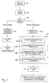
- ein Ablaufdiagramm zum erfindungsgemäßen Verfahren zum Steuern eines Roboters bei Spannungsabfall;
- Figur 3:
- ein Ablaufdiagramm des erfindungsgemäßen Verfahrens zum Wiederanfahren des Roboters nach Spannungsabfall;
- Figur 4:
- ein Ablaufdiagramm zur Sicherung des Zustandes des Speicherinhaltes bei Beendigung des Arbeitsablaufs nach Spannungsabfall und zur Wiederaufnahme des Arbeitens nach Spannungswiederkehr.
- Im dargestellten Ausführungsbeispiel basiert die Steuerung 1 für einen Roboter 2 auf einem PC-Computer mit einer PC-Hauptplatine 3 mit mindestens einem PC-Pentium-Prozessor, auf dem sowohl ein nichtechtzeitfähiges Standard-PC-Betriebssystem 4 wie Windows 95 oder 98, als auch ein Echtzeit-Betriebpsystem wie VxWorks, gemeinsam arbeiten. Das Standard-PC-Betriebssystem 4 und die Echtzeit-Betriebssystem 5 nutzen gemeinsam den Arbeitsspeicher 6. Mit der Hauptplatine 3 ist ein Massenspeicher 7 verbunden.
- Das Standard-Betriebssystem 4 dient insbesondere zur Kommunikation mit einem Bediener sowie mit Massenspeicher-Medien. Hierzu ist es mit mehreren Bediener-Peripheriegeräten verbunden sowie über eine Grafikkarte 8 mit einem Monitor 9 und mit der Anzeige 11a einer Steuereinheit 11, ie wiederum mit einer mit dem Echtzeit-Betriebssystem 5 verbundenen Robotersteuerkarte 12 kommuniziert. Die Robotersteuerkarte 12 steuert über ein Leistungsmodul 13 den Roboter 2, dessen mittels Bewegungs- und Positionsmessern etc. gemessenen Positionen und Bewegungsdaten über eine Wandlereinheit 14 der Robotersteuerkarte 12 mitgeteilt werden. Insbesondere die Robotersteuerkarte 12 und das Echtzeit-Betriebssystem 5 stehen über diverse Kommunikations-Meßstellen 16 mit Industrieperipherie, Wegsteuerungen für Werkzeuge, insbesondere Kleb- und Schweißeinrichtungen etc. in Verbindung.
- Die Erfindung sieht nun bei einer solchen Steuerung ein Steuermodul vor, mit dem der Ablauf der Steuerung sowie der Roboter im Falle eines Spannungsabfalles behandelt bzw. gesteuert wird.
- Das nicht dargestellte Netzteil der Steuerung 1 weist einen ebenfalls nicht dargestellten Spannungsdetektor auf. Über diesen stellt das Betriebssystem in einem ersten Schritt 21 einen eventuellen Spannungsabfall fest, den es in einem Schritt 22 dem Steuermodul meldet. Dieses initialisiert im Schritt 23 ein Programm (Figur 4), welches in einem weiteren Schritt 31, sowohl über die Peripherie-Kommunikationsschnittstellen 16 gesteuerten Arbeitsprozesse abbricht.
- Weiter wird der Roboter 2 bahnnah abgebremst, d.h. entsprechend der vorgegebenen Bahn in einen Ruhezustand überführt, bis die noch vorhandene Antriebsenergie verbraucht ist. Hierbei kann es sich um in dem Gleichspannungszwischenkreis der Servoumrichter (Kondensatorbatterie) des Roboters gespeicherte Energie sowie ggf. kinetische Energie der Roboterelemente und die hierdurch bei Abbremsen in Bewegung befindliche Achsen resultierende und in den Zwischenkreis rückgespeiste Energie handeln. An Umkehrpunkten sowie bei Aufwärtsbewegungen ist der Stillstand der Roboterachsen schnell zu erreichen, im letzteren Fall trägt hierzu die Gravitationskraft wesentlich bei. Längere Bremszeiten sind bei hohen Geschwindigkeiten mit großer Trägheit erforderlich.
- Nach kontrolliertem Abbruch aller externen bzw. mechanischen Prozesse insbesondere der Roboterbewegungen erfolgt eine Zustandsmitteilung an externen Steuerungen (Schritt 32), woraufhin in einem Schritt 33 eine entsprechende Meldung an das Steuerungsmodul erfolgt, welches im Schritt 24 die Roboterprogramme (in ihrem dann gegebenen Zustand) auf den Massenspeicher 7 sichert. Im Schritt 25 geht das Echtzeit-Betriebssystem nach kontrolliertem Abbruch aller Prozesse und insbesondere der Roboterbewegung in einen definierten Zustand über und sichert anschließend das komplette Echtzeit-Betriebssystem (Schritt 26 bzw. 26'), mit einer Spannungsabfall-Information (Schritt 27 bzw. 27'), die bei einem Neustart bewirkt, daß dieser einen "Warmstart" imitiert, bei dem das Echtzeit-Betriebssystem und die Roboterprogramme mit allen gespeicherten Zuständen vom Massenspeicher 7 übernommen werden und die Steuerung von diesem Zustand weitergeführt wird.
- Anschließend schaltet das Steuerungsmodul im Schritt 28 die Spannungsversorgung des bis hierher sichernden Akku bzw. eine entsprechende Batterie ab.
- Ergibt sich während des vorstehend beschriebenen Abbruchs der Roboterbewegung, der Peripheriearbeiten sowie während des Herunterfahrens des Systems ein Fehler, so wird dieser Fehlerzustand zwar auch auf dem Massenspeicher 7 zwecks Ermöglichung einer Analyse gespeichert; die Spannungsausfall-Information ist aber eine solche, daß der nächste Start des Systems ein "Kaltstart" ist, bei dem von Standarddaten ausgegangen wird, da ein Weiterarbeiten bei einem solchen Fehlerzustand nicht sinnvoll ist.
- Bei erneuter Spannungsversorgung wird in der Steuerung 1 wie üblich, das nicht-echtzeitfähige Standard-PC-Betriebssystem (Windows 95) gestartet (Schritt 41), das mit Schritt 42 das Steuerungsmodul aufruft. Dieses betrifft die beim beendenden Schritt 27 abgelegte Spannungsausfall-Information und führt ggf. den zur Weiterverführung der Robotertätigkeit am erreichten Arbeitspunkt erforderlichen "Warmstart", d.h. einen Wiederanlauf des Systems mit den gesicherten Daten durch (Schritte 43, 44 bzw. 44').
- Im folgenden (Schritt 45) erfolgt die Restaurierung des Steuerungszustandes bei Spannungsausfall. Hierzu wird das Echtzeit-Betriebssystem 5 mit den Roboterprogrammen vom Massenspeicher 7 gelesen und im Arbeitsspeicher 6 (Schritt 46-48) restauriert. Anschließend wird auch für das Ausgangsabbild der peripheren Systeme im Zustand des Abbruchs wieder hergestellt (Schritt 49).
- Nach Wiederherstellung der Daten im Arbeitsspeicher 6 werden die Bedieneroberfläche und insbesondere auch die Anzeigegeräte 9, 11 wieder in den den Abbruchstatus wiedergebenden Zustand versetzt (Schritt 50). Das Roboterprogramm steht an de Stelle des früheren Abbruchs. (Schritt 34, 35 in Figur 4) und überprüft nach einem Startsignal, ob alle Fehler bereinigt und quittiert sind (Schritt 36). Es erfolgt eine Zustandsmitteilung an die externen Steuerungen (Schritt 37) und die peripheren Prozesse werden fortgesetzt bzw. neugestartet (Schritt 38). Anschließend kann das Hauptprogramm in dem durch den Spannungsabfall abgebrochenen Ablauf weiterverarbeiten (Schritt 39). Ein beim Abbruch festgestellter Fehler (Fig.2) führt zu einem üblichen Kaltstart (Fig.3).
Claims (5)
- Verfahren zur Behandlung des Spannungsabfalls zumindest im Steuerteil bei einem Roboter mit einer PC-Steuerung aus einer Kombination eines Echtzeit-Betriebssystems zum zeitkritischen Steuern und.Regeln der Roboterbewegung und eines Standard-PC-Betriebssystems zur Kommunikation mit einem Bediener, wobei bei Spannungsabfall ein Batterie-Akku-Betrieb erfolgt, dadurch gekennzeichnet, dassa) eine laufende Roboterbewegung und ggf. Anwendungsarbeiten beendet oder definiert abgebrochen werden,b) der Roboter entsprechend einer vorgegebenen Bahn abgebremst wird, indem die Steuerung und Regelung des Roboters solange aktiv bleiben, bis noch vorhandene Antriebsenergie verbraucht ist,c) anschließend Arbeitsprozesse der Steuerung abgeschlossen werden undd) ausschließlich das Echtzeit-Betriebssystem sowie Robotersteuerungsprogramme betreffende Inhalte des Arbeitsspeichers zum Beendigungszeitpunkt auf zumindest einem Massenspeicher gespeichert werden.
- Verfahren zum Wiederanfahren eines Roboters nach einem gemäß dem Verfahren nach Anspruch 1 erfolgten Stillsetzen des Roboter, dadurch gekennzeichnet, dass das Standard-PC-Betriebssystem in üblicher Weise in den Arbeitsspeicher geladen und gestartet wird und dass die den Zustand des Echtzeit-Betriebssystems sowie der Roboterprogramme im Beendigungszustand betreffenden Inhalte von den/dem Massenspeicher (n) in den Arbeitsspeicher übernommen und die Steuerung des Roboter im Beendigungszustand wieder aufgenommen wird.
- Verfahren nach Anspruch 1 oder 2, dadurch gekennzeichnet, dass die das Echtzeit-Betriebssystem sowie Robotersteuerungsprogramme betreffenden Inhalte des Arbeitsspeichers als Bild (Image) auf dem/den Massenspeicher(n) gespeichert werden.
- Verfahren nach Anspruch 2 oder 3, dadurch gekennzeichnet, dass ein den Zustand des Echtzeit-Betriebssystems sowie der Robotersteuerung enthaltendes Bild (Image) von dem/den-Massenspeicher(n) in den Arbeitsspeicher übernommen wird.
- Verfahren nach einem der Ansprüche 2 bis 4, dadurch gekennzeichnet, dass beim Wiederanfahren auch die Steuerung sonstiger Prozessperipherie im Beendigungszustand wieder aufgenommen wird.
Applications Claiming Priority (2)
| Application Number | Priority Date | Filing Date | Title |
|---|---|---|---|
| DE19857436A DE19857436A1 (de) | 1998-12-12 | 1998-12-12 | Verfahren zum Behandeln des Spannungsabfalls in der Steuerung eines Roboters und zum Wiederanfahren eines Roboters nach Spannungsabfall |
| DE19857436 | 1998-12-12 |
Publications (3)
| Publication Number | Publication Date |
|---|---|
| EP1011035A2 EP1011035A2 (de) | 2000-06-21 |
| EP1011035A3 EP1011035A3 (de) | 2003-04-09 |
| EP1011035B1 true EP1011035B1 (de) | 2006-03-29 |
Family
ID=7890906
Family Applications (1)
| Application Number | Title | Priority Date | Filing Date |
|---|---|---|---|
| EP99123763A Expired - Lifetime EP1011035B1 (de) | 1998-12-12 | 1999-11-30 | Verfahren zum Behandeln des Spannungsabfalls in der Steuerung eines Roboters und zum Wiederanfahren eines Roboters nach Spannungsabfall |
Country Status (3)
| Country | Link |
|---|---|
| US (1) | US6356806B1 (de) |
| EP (1) | EP1011035B1 (de) |
| DE (2) | DE19857436A1 (de) |
Families Citing this family (51)
| Publication number | Priority date | Publication date | Assignee | Title |
|---|---|---|---|---|
| JP4122652B2 (ja) * | 1999-09-27 | 2008-07-23 | 松下電器産業株式会社 | ロボットの制御装置 |
| JP2001222309A (ja) * | 2000-02-10 | 2001-08-17 | Yaskawa Electric Corp | ロボット制御装置 |
| JP2001269884A (ja) * | 2000-03-28 | 2001-10-02 | Matsushita Electric Ind Co Ltd | 産業用ロボット |
| SE0001312D0 (sv) * | 2000-04-10 | 2000-04-10 | Abb Ab | Industrirobot |
| DE10032096A1 (de) * | 2000-07-01 | 2002-01-24 | Kuka Roboter Gmbh | Geräteverbund und Steuerschrank für einen solchen |
| WO2002066210A1 (en) * | 2001-02-22 | 2002-08-29 | Mitsubishi Denki Kabushiki Kaisha | Robot control device |
| JP3673725B2 (ja) * | 2001-04-05 | 2005-07-20 | ファナック株式会社 | ロボット用情報処理システム |
| ITTO20010553A1 (it) * | 2001-06-08 | 2002-12-08 | Comau Spa | Sistema di controllo per robot. |
| JP2003001576A (ja) * | 2001-06-25 | 2003-01-08 | Matsushita Electric Ind Co Ltd | ロボット制御装置およびその制御方法 |
| AT412176B (de) | 2001-06-26 | 2004-10-25 | Keba Ag | Tragbare vorrichtung zumindest zur visualisierung von prozessdaten einer maschine, eines roboters oder eines technischen prozesses |
| JP2003108208A (ja) * | 2001-09-28 | 2003-04-11 | Matsushita Electric Ind Co Ltd | ロボット制御装置およびロボットと生産設備 |
| JP2003117863A (ja) * | 2001-10-16 | 2003-04-23 | Fanuc Ltd | ロボットシミュレーション装置 |
| SE0103532D0 (sv) * | 2001-10-23 | 2001-10-23 | Abb Ab | Industrial robot system |
| WO2003086718A1 (en) * | 2002-04-12 | 2003-10-23 | Mitsubishi Denki Kabushiki Kaisha | Robot |
| EP1359485B1 (de) * | 2002-05-03 | 2015-04-29 | Infineon Technologies AG | Steuer- und Überwachungssystem |
| US6678582B2 (en) * | 2002-05-30 | 2004-01-13 | Kuka Roboter Gmbh | Method and control device for avoiding collisions between cooperating robots |
| DE10226140A1 (de) * | 2002-06-13 | 2004-01-08 | Kuka Roboter Gmbh | Verfahren und Vorrichtung zum Vermeiden von Kollisionen zwischen Industrierobotern und anderen Objekten |
| DE10228863B4 (de) * | 2002-06-27 | 2019-10-31 | Sew-Eurodrive Gmbh & Co Kg | Anlage |
| DE10234233A1 (de) * | 2002-07-27 | 2004-02-05 | Kuka Roboter Gmbh | Verfahren zum Austausch von Daten zwischen Steuerungen von Maschinen, insbesondere von Robotern |
| US6836700B2 (en) * | 2002-07-29 | 2004-12-28 | Advanced Robotic Technologies, Inc. | System and method generating a trajectory for an end effector |
| DE10236392A1 (de) * | 2002-08-08 | 2004-02-19 | Kuka Roboter Gmbh | Verfahren und Vorrichtung zum Steuern von Handhabungsgeräten |
| ITTO20020862A1 (it) * | 2002-10-04 | 2004-04-05 | Comau Spa | Sistema di programmazione per robot o simili apparati |
| ITTO20020863A1 (it) * | 2002-10-04 | 2004-04-05 | Comau Spa | Terminale portatile di comando, programmazione e/ o |
| JP3950832B2 (ja) * | 2002-10-08 | 2007-08-01 | ファナック株式会社 | ロボット制御装置 |
| US6871115B2 (en) * | 2002-10-11 | 2005-03-22 | Taiwan Semiconductor Manufacturing Co., Ltd | Method and apparatus for monitoring the operation of a wafer handling robot |
| DE10255037A1 (de) * | 2002-11-26 | 2004-06-09 | Kuka Roboter Gmbh | Verfahren und Vorrichtung zum Bearbeiten eines Werkstücks |
| FR2850600B1 (fr) * | 2003-02-04 | 2006-01-13 | Staubli Sa Ets | Robot multi-axes equipe d'un systeme de commande |
| JP3708083B2 (ja) * | 2003-02-28 | 2005-10-19 | ファナック株式会社 | ロボット教示装置 |
| JP4441409B2 (ja) * | 2003-03-25 | 2010-03-31 | ローツェ株式会社 | ロボットシミュレーション装置、および、シミュレーションプログラム |
| JP3834307B2 (ja) * | 2003-09-29 | 2006-10-18 | ファナック株式会社 | ロボットシステム |
| JP3708097B2 (ja) * | 2003-10-08 | 2005-10-19 | ファナック株式会社 | ロボットの手動送り装置 |
| DE10354642A1 (de) * | 2003-11-22 | 2005-06-16 | Bayerische Motoren Werke Ag | Vorrichtung und Verfahren zum Programmieren eines Industrieroboters |
| US8825194B2 (en) * | 2003-12-18 | 2014-09-02 | International Business Machines Corporation | Global positioning system location information for an automated data storage library |
| US20050283275A1 (en) * | 2004-06-17 | 2005-12-22 | Kabushiki Kaisha Koyama | Method of teaching articulated robot and control equipment of articulated robot |
| US8000837B2 (en) * | 2004-10-05 | 2011-08-16 | J&L Group International, Llc | Programmable load forming system, components thereof, and methods of use |
| CN101194213A (zh) * | 2005-03-04 | 2008-06-04 | 范努克机器人技术美国有限公司 | 教导装置和可编程控制器的活动连接 |
| JP2007144524A (ja) * | 2005-11-24 | 2007-06-14 | Denso Wave Inc | ロボットの干渉回避方法およびロボット |
| JP4171488B2 (ja) * | 2005-12-16 | 2008-10-22 | ファナック株式会社 | オフラインプログラミング装置 |
| US8249745B2 (en) * | 2006-01-17 | 2012-08-21 | Musashi Engineering, Inc. | Work robot excellent in work resumption |
| US8265793B2 (en) * | 2007-03-20 | 2012-09-11 | Irobot Corporation | Mobile robot for telecommunication |
| US7822492B2 (en) * | 2007-10-19 | 2010-10-26 | Ge Intelligent Platforms | Methods and systems for operating an automated system using a process definition model |
| DE102008007438B4 (de) | 2008-02-01 | 2012-11-29 | Abb Ag | Verfahren zum Wiederanfahren eines Roboters |
| EP2479630A1 (de) * | 2011-01-25 | 2012-07-25 | Siemens Aktiengesellschaft | Verfahren zur kollisionsfreien Überführung einer Anlage aus einem Scheinausmodus in einen Betriebsmodus |
| JP5839806B2 (ja) * | 2011-02-02 | 2016-01-06 | キヤノン株式会社 | ロボット制御装置及びロボット制御方法 |
| US8972061B2 (en) | 2012-11-02 | 2015-03-03 | Irobot Corporation | Autonomous coverage robot |
| US9162357B2 (en) * | 2013-06-26 | 2015-10-20 | Canon Kabushiki Kaisha | Control method for robot system and robot system |
| US9704043B2 (en) | 2014-12-16 | 2017-07-11 | Irobot Corporation | Systems and methods for capturing images and annotating the captured images with information |
| US10894318B2 (en) * | 2016-02-23 | 2021-01-19 | Abb Schweiz Ag | Robot controller system and method therefor |
| US20180272526A1 (en) * | 2017-03-21 | 2018-09-27 | Seiko Epson Corporation | Control device, teaching device, and robot system |
| JP6984499B2 (ja) * | 2018-03-12 | 2021-12-22 | オムロン株式会社 | FA(Factory Automation)システム、コントローラ、および制御方法 |
| WO2025076034A1 (en) * | 2023-10-02 | 2025-04-10 | Intuitive Surgical Operations, Inc. | Restoring the state of systems after a system restart |
Family Cites Families (17)
| Publication number | Priority date | Publication date | Assignee | Title |
|---|---|---|---|---|
| DE6911133U (de) | 1969-03-20 | 1969-07-24 | Heribert & Guenther Hunstiger | Tapeziertisch |
| SE436848B (sv) * | 1982-06-28 | 1985-01-28 | Asea Ab | Styrsystem for industrirobot |
| US4983818A (en) * | 1989-01-30 | 1991-01-08 | Metrologic Instruments, Inc. | Data acquisition system with laser scanner module |
| US5117325A (en) * | 1990-01-23 | 1992-05-26 | Cooper Industries, Inc. | Controllable recloser for power line |
| JPH03256693A (ja) * | 1990-03-08 | 1991-11-15 | Fanuc Ltd | ロボットの停電制御方式 |
| JPH04340118A (ja) * | 1990-06-05 | 1992-11-26 | Seiko Epson Corp | コンピュータ |
| US5294782A (en) * | 1991-09-27 | 1994-03-15 | Khyber Technologies Corporation | Integrated portable device for point of sale transactions |
| US5432510A (en) * | 1993-03-22 | 1995-07-11 | Matthews; Walter S. | Ambidextrous single hand chordic data management device |
| DE4340069A1 (de) | 1993-11-24 | 1995-06-01 | Siemens Ag | Verfahren zum Sichern von Daten auf dem Plattenspeicher eines Rechners |
| US6134102A (en) * | 1995-07-22 | 2000-10-17 | Kuka Roboter Gmbh | Programming device |
| DE19614201C2 (de) * | 1996-04-10 | 1999-08-12 | Agie Ag Ind Elektronik | Verfahren und Vorrichtung zur Steuerung einer Werkzeugmaschine, insbesondere einer Funkenerosionsmaschine |
| US5765001A (en) * | 1996-04-29 | 1998-06-09 | International Business Machines Corporation | Computer system which is operative to change from a normal operating state to a suspend state when a power supply thereof detects that an external source is no longer providing power to said power supply at a predetermined level |
| JP3832517B2 (ja) | 1996-07-05 | 2006-10-11 | セイコーエプソン株式会社 | ロボット用コントローラ及びその制御方法 |
| WO1998037466A1 (en) * | 1997-02-19 | 1998-08-27 | Mitsubishi Denki Kabushiki Kaisha | Personal computer-incorporated numerical controller |
| JP3269003B2 (ja) * | 1997-05-12 | 2002-03-25 | 川崎重工業株式会社 | ロボット制御装置 |
| US6178523B1 (en) * | 1998-06-12 | 2001-01-23 | Philips Consumer Communications Lp | Battery-operated device with power failure recovery |
| TW406221B (en) * | 1998-07-23 | 2000-09-21 | Via Tech Inc | Power switching apparatus for increasing the battery lifetime and the full-time operation apparatus |
-
1998
- 1998-12-12 DE DE19857436A patent/DE19857436A1/de not_active Ceased
-
1999
- 1999-11-30 DE DE59913277T patent/DE59913277D1/de not_active Expired - Fee Related
- 1999-11-30 EP EP99123763A patent/EP1011035B1/de not_active Expired - Lifetime
- 1999-12-10 US US09/459,269 patent/US6356806B1/en not_active Expired - Lifetime
Also Published As
| Publication number | Publication date |
|---|---|
| DE19857436A1 (de) | 2000-06-21 |
| US6356806B1 (en) | 2002-03-12 |
| DE59913277D1 (de) | 2006-05-18 |
| EP1011035A2 (de) | 2000-06-21 |
| EP1011035A3 (de) | 2003-04-09 |
Similar Documents
| Publication | Publication Date | Title |
|---|---|---|
| EP1011035B1 (de) | Verfahren zum Behandeln des Spannungsabfalls in der Steuerung eines Roboters und zum Wiederanfahren eines Roboters nach Spannungsabfall | |
| EP1035953B1 (de) | Überwachungs- und steuergerät sowie verfahren zur überwachung einer technischen anlage mit erhöhten sicherheitsanforderungen, insbesondere eines handhabungsgerätes | |
| DE2904080C2 (de) | Steueranordnung für mindestens eine Werkzeugmaschine | |
| DE69031716T2 (de) | Verfahren und Vorrichtung zum Schutz gegen Energieversorgungsfehler | |
| EP2600992B1 (de) | Biegepresse mit einer werkteil-positionier-vorrichtung sowie ein verfahren zum betrieb | |
| DE3806966C2 (de) | ||
| DE3208435C2 (de) | Steuerungsvorrichtung zum Führen eines Lichtbogenschweißautomaten | |
| EP2355957B1 (de) | Verfahren und vorrichtung zum steuern eines manipulatorsystems | |
| DE102020126209A1 (de) | Roboter | |
| DE1966793B2 (de) | Numerische Steuereinrichtung für eine mehrachsig arbeitende Werkzeugmaschine | |
| DE102017004822A1 (de) | Numerische Steuerung mit einer Programmkorrektur-Assistenzfunktion für eine Alarmlösung | |
| DE102004041051A1 (de) | Intelligentes Störungsmanagement | |
| DE19753992A1 (de) | Erodiermaschine | |
| DE102020134409B3 (de) | Zwischeneinheit für ein Feldgerät mit einem Energiespeicher und Verfahren | |
| EP3803519B1 (de) | Verfahren zum betreiben eines industrieroboters sowie steuervorrichtung hierfür | |
| DE2624733A1 (de) | Lernfaehige elektronische steuereinheit mit mikrocomputer | |
| DE102011010988B4 (de) | Verfahren zum Betreiben eines Serviceaggregats und Textilmaschine mit einem Serviceaggregat | |
| EP0945799B1 (de) | Verfahren und Einrichtung zum Verhindern der Einlagerung nicht mehr aktueller Datentelegramme aus einer Datenvorverarbeitung in die Speicher eines Rechners | |
| EP3993960A1 (de) | Anhalten einer produktionsmaschine auf kollisionsfreier bahn | |
| DE112021004730T5 (de) | Robotersystem und Roboter-Betriebsverfahren | |
| DE112018000800B4 (de) | Roboter-Steuereinrichtung, Robotersystem und Roboter-Steuerverfahren | |
| DE4210844C2 (de) | Programmierbare Steuerung und Verfahren zur Überwachung eines Ablaufprogrammes für eine programmierbare Steuerung | |
| DE102020121199A1 (de) | Steuerungseinrichtung einer Betriebsanlage | |
| DE10300605A1 (de) | Ablaufsteuerung mit definierter Behebung von Ausnahmezuständen | |
| DE102019007101A1 (de) | Vorrichtung und Verfahren zur Bestimmung der Lebensdauer eines mechatronischen Systems sowie Roboter |
Legal Events
| Date | Code | Title | Description |
|---|---|---|---|
| PUAI | Public reference made under article 153(3) epc to a published international application that has entered the european phase |
Free format text: ORIGINAL CODE: 0009012 |
|
| AK | Designated contracting states |
Kind code of ref document: A2 Designated state(s): AT BE CH CY DE DK ES FI FR GB GR IE IT LI LU MC NL PT SE |
|
| AX | Request for extension of the european patent |
Free format text: AL;LT;LV;MK;RO;SI |
|
| PUAL | Search report despatched |
Free format text: ORIGINAL CODE: 0009013 |
|
| AK | Designated contracting states |
Kind code of ref document: A3 Designated state(s): AT BE CH CY DE DK ES FI FR GB GR IE IT LI LU MC NL PT SE Designated state(s): AT BE CH CY DE DK ES FI FR GB GR IE IT LI LU MC NL PT SE |
|
| AX | Request for extension of the european patent |
Extension state: AL LT LV MK RO SI |
|
| 17P | Request for examination filed |
Effective date: 20030410 |
|
| AKX | Designation fees paid |
Designated state(s): DE FR GB IT SE |
|
| 17Q | First examination report despatched |
Effective date: 20040615 |
|
| GRAP | Despatch of communication of intention to grant a patent |
Free format text: ORIGINAL CODE: EPIDOSNIGR1 |
|
| GRAS | Grant fee paid |
Free format text: ORIGINAL CODE: EPIDOSNIGR3 |
|
| GRAA | (expected) grant |
Free format text: ORIGINAL CODE: 0009210 |
|
| AK | Designated contracting states |
Kind code of ref document: B1 Designated state(s): DE FR GB IT SE |
|
| PG25 | Lapsed in a contracting state [announced via postgrant information from national office to epo] |
Ref country code: IT Free format text: LAPSE BECAUSE OF FAILURE TO SUBMIT A TRANSLATION OF THE DESCRIPTION OR TO PAY THE FEE WITHIN THE PRE;WARNING: LAPSES OF ITALIAN PATENTS WITH EFFECTIVE DATE BEFORE 2007 MAY HAVE OCCURRED AT ANY TIME BEFORE 2007. THE CORRECT EFFECTIVE DATE MAY BE DIFFERENT FROM THE ONE RECORDED.SCRIBED TIME-LIMIT Effective date: 20060329 |
|
| REG | Reference to a national code |
Ref country code: GB Ref legal event code: FG4D Free format text: NOT ENGLISH |
|
| GBT | Gb: translation of ep patent filed (gb section 77(6)(a)/1977) |
Effective date: 20060424 |
|
| REF | Corresponds to: |
Ref document number: 59913277 Country of ref document: DE Date of ref document: 20060518 Kind code of ref document: P |
|
| REG | Reference to a national code |
Ref country code: SE Ref legal event code: TRGR |
|
| ET | Fr: translation filed | ||
| PLBE | No opposition filed within time limit |
Free format text: ORIGINAL CODE: 0009261 |
|
| STAA | Information on the status of an ep patent application or granted ep patent |
Free format text: STATUS: NO OPPOSITION FILED WITHIN TIME LIMIT |
|
| 26N | No opposition filed |
Effective date: 20070102 |
|
| PGFP | Annual fee paid to national office [announced via postgrant information from national office to epo] |
Ref country code: DE Payment date: 20081127 Year of fee payment: 10 |
|
| PGFP | Annual fee paid to national office [announced via postgrant information from national office to epo] |
Ref country code: IT Payment date: 20081126 Year of fee payment: 10 |
|
| PGFP | Annual fee paid to national office [announced via postgrant information from national office to epo] |
Ref country code: GB Payment date: 20081126 Year of fee payment: 10 |
|
| GBPC | Gb: european patent ceased through non-payment of renewal fee |
Effective date: 20091130 |
|
| PG25 | Lapsed in a contracting state [announced via postgrant information from national office to epo] |
Ref country code: DE Free format text: LAPSE BECAUSE OF NON-PAYMENT OF DUE FEES Effective date: 20100601 |
|
| PG25 | Lapsed in a contracting state [announced via postgrant information from national office to epo] |
Ref country code: GB Free format text: LAPSE BECAUSE OF NON-PAYMENT OF DUE FEES Effective date: 20091130 |
|
| PG25 | Lapsed in a contracting state [announced via postgrant information from national office to epo] |
Ref country code: IT Free format text: LAPSE BECAUSE OF NON-PAYMENT OF DUE FEES Effective date: 20091130 |
|
| REG | Reference to a national code |
Ref country code: FR Ref legal event code: PLFP Year of fee payment: 17 |
|
| REG | Reference to a national code |
Ref country code: FR Ref legal event code: PLFP Year of fee payment: 18 |
|
| REG | Reference to a national code |
Ref country code: FR Ref legal event code: PLFP Year of fee payment: 19 |
|
| REG | Reference to a national code |
Ref country code: FR Ref legal event code: PLFP Year of fee payment: 20 |
|
| PGFP | Annual fee paid to national office [announced via postgrant information from national office to epo] |
Ref country code: SE Payment date: 20181113 Year of fee payment: 20 |
|
| PGFP | Annual fee paid to national office [announced via postgrant information from national office to epo] |
Ref country code: FR Payment date: 20181011 Year of fee payment: 20 |
|
| REG | Reference to a national code |
Ref country code: SE Ref legal event code: EUG |