EP1011990B1 - Procede et dispositif de montage de rayons dans une jante d'une roue a rayons - Google Patents
Procede et dispositif de montage de rayons dans une jante d'une roue a rayonsInfo
- Publication number
- EP1011990B1 EP1011990B1 EP98941928A EP98941928A EP1011990B1 EP 1011990 B1 EP1011990 B1 EP 1011990B1 EP 98941928 A EP98941928 A EP 98941928A EP 98941928 A EP98941928 A EP 98941928A EP 1011990 B1 EP1011990 B1 EP 1011990B1
- Authority
- EP
- European Patent Office
- Prior art keywords
- transverse plane
- spoke wheel
- spoke
- nipple
- rim
- Prior art date
- Legal status (The legal status is an assumption and is not a legal conclusion. Google has not performed a legal analysis and makes no representation as to the accuracy of the status listed.)
- Expired - Lifetime
Links
Images
Classifications
-
- B—PERFORMING OPERATIONS; TRANSPORTING
- B60—VEHICLES IN GENERAL
- B60B—VEHICLE WHEELS; CASTORS; AXLES FOR WHEELS OR CASTORS; INCREASING WHEEL ADHESION
- B60B31/00—Apparatus or tools for assembling or disassembling wheels
- B60B31/02—Apparatus or tools for assembling or disassembling wheels for tightening or straightening wire spokes in situ; for extracting spokes from wheels
Definitions
- the present invention relates to a method wherein the presence of a nipple hole in a rim of a spoke wheel is optically detected in a transverse plane of said spoke wheel, after which a spoke is fixed in said nipple hole.
- the present invention furthermore relates to a device intended for fixing spokes in nipple holes present in a rim of a spoke wheel, which device comprises:
- the measuring means measure the position of each nipple hole with respect to a reference point both in the axial direction and in the circumferential direction of the rim, and said measuring data are recorded.
- the measuring means also include a wheel running over said rim, which cooperates with a pulse counter and a CCD camera so as to determine the spacing between the various nipple holes during a measuring cycle.
- the measuring data which are relevant for the position of the various nipple holes are stored in a memory for conversion into control signals for the control means that are present.
- a method and a device as referred to in the introduction of claims 1 and 5 respectively is known from EP-A-0 476 750.
- optical detection of a nipple hole - in a transverse plane, which is a radial plane in which the longitudinal axis of the spoke wheel lies - also takes place by means of detection means in the form of measuring means, which determine the position of each of the nipple holes.
- the position of all nipple holes is measured and stored in a memory by a scanning and registration element in said means during a preceding scanning revolution, for the purpose of setting the position of the screwing means - which are present in a transverse plane of the spoke wheel - with respect to the rim as a function of the positions of the holes in the rim.
- the object of the present invention is to provide an improved and simplified method and device, wherein individual determination of the co-ordinates of the nipple holes does not take place.
- the method according to the invention is characterized in that the detection of the nipple hole and the fixation of the spoke in the nipple hole take place in the same transverse plane of the spoke wheel.
- the device according to the invention is characterized in that said optical detection means and said screwing means are arranged in such a manner that their connecting line lies in the same transverse plane of the spoke wheel.
- the advantage of the method and the device according to the invention is that the optical detection means do not need to be relatively complex measuring means, but that they only need to function as presence detectors, since their only function is to establish momentaneously whether a nipple hole is present at a specified location.
- the presence of a memory for the individual storage and reading out of the coordinate data or measuring data of the nipple holes is no longer necessary, either.
- Another advantage is that the procedure as a whole has been improved, since it has been shortened, due to the fact that a preceding measuring cycle or scanning revolution for determining nipple hole positions is no longer required. After all, once the nipple hole has been detected, the nipple is directly fixed therein by the screwing means. In addition to the fact that less hardware and software is required, also time is saved, which time may now be used efficiently for increasing the production of the device in the form of spoke wheels comprising fixed spokes.
- Another important advantage of the method and the device according to the invention is the fact that a deformation or an irregular shape of the rim, for example if said rim does not rotate exactly about the centre of the spoke wheel, or a difference in movement between the driven side of the rim and the non-driven side thereof, no longer plays a role at the location of the screwing means, which, after all, are present in the same transverse plane of the spoke wheel as the detection means. Since detection takes place in the same plane as that in which the screwing means are present, the prior art need for a time-consuming position correction, which made it impossible to realise a high operating speed, has been completely eliminated.
- An advantageous aspect is furthermore the fact that there is no longer a space problem at the location where previously correction of the above-mentioned errors took place in a manner wherein rim driving means and screwing means had to be assembled within 90°.
- the transverse plane may extend substantially parallel to the longitudinal axis of the spoke wheel, or through the centre of the spoke wheel, or be an exactly radial plane, within which the longitudinal axis of the spoke wheel is completely positioned.
- a further simplification from a mechanical and a control engineering point of view is accomplished by making the screwing means and/or the optical detection means movable in said transverse plane, and possibly only in said transverse plane.
- the light transmitter and the light receiver of the optical detection means are rigidly interconnected for the same reason, for example on a yoke, so that they can be moved in the transverse plane by simple pneumatic, hydraulic or electric means.
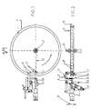
- Figures 1 and 2 are a front view and a plan view respectively of apart of a device 1 that is relevant for the present description of the figures, which device is suitable for fixing spokes 2 in a rim 3 of a spoke wheel 4, which fixing may or may not take place automatically.
- Device 1 comprises optical detection means 5, which for example comprise a light transmitter 6 on one side of rim 3 and a light receiver 7 on the other side thereof.
- the figure shows an embodiment wherein one side is positioned outside the spoke wheel and the other side is positioned within spoke wheel 4.
- the light transmitter includes a light source, for example a lamp or a laser
- light receiver 7 for example includes a CCD camera or a light sensor, such as a four-quadrant sensor.
- spoke 2 is fixed in rim 3 by means of the screwing means 9 present in device 1.
- optical detection means 5 and screwing means 9 are positioned in practically one and the same transverse plane, which extends substantially perpendicularly to the plane in which spoke wheel 4 is clamped. Said latter plane is the plane of drawing of Figure 1.
- the transverse plane may extend parallel to the longitudinal axis of spoke wheel 4, or through the centre 11 of spoke wheel 4, and in the illustrated embodiment, which is a symmetric preferred embodiment of simple construction, longitudinal axis 10 lies completely within said plane, which is shown most clearly in Figure 1.
- the nipple After detection of the nipple hole by light receiver/sensor/camera 7 has taken place, without preceding measurement of all coordinates of all nipple hole positions, the nipple is screwed onto spoke 2 without interim rotation of the rim by means of rim moving elements which are generally present. Thus, one measuring cycle can be omitted, whilst furthermore tolerances and deformations of rim 3 resulting from said movement will no longer play a role. In addition, the presence of a memory for the storage of all coordinates of all nipple hole positions is no longer required, which leads to a simplification of the required electronics as well.
- nipple hole 8 Besides detection of the nipple hole 8, also detection of position of the valve hole takes place, which valve hole has a slightly larger diameter than a nipple hole, which position is subsequently used as a reference for nipple hole detection. Given the number of spokes to be mounted and the spoke wheel diameter, the spacing between the nipple holes automatically follows. Detection of the dimension of a hole is also important for detection of grip or handle holes, which are used in fixing supports therein. Said supports are taken hold of when spoke wheels of a wheelchair are being moved by disabled persons.
- light transmitter 6 and light receiver 7 are rigidly interconnected by means of a yoke or frame 12, which only needs to be capable of being moved and swung to one side in the transverse plane, in the direction indicated by arrow A, by moving elements 13. Also screwing means 9 only need to be movable in the transverse plane, in the direction indicated by arrows B and C. Movement B enables an optimum operation with various types of nipple hole positions, generally on either side of median line 14, whilst movement C is used for approaching and scanning and for screwing the nipples onto the spokes. Movement in the direction indicated by arrow B takes place by means of further moving elements 15, which, like moving elements 13 and light transmitter 5, will be electrically connected to a suitably programmed micro computer or mini computer (not shown).
Landscapes
- Engineering & Computer Science (AREA)
- Mechanical Engineering (AREA)
- Length Measuring Devices By Optical Means (AREA)
Claims (14)
- Procédé dans lequel sur un plan transversal de roue à rayons (4), est détectée de manière optique la présence d'un trou de raccord à vis (8), lequel se trouve sur une jante (3) de la roue à rayon, après quoi un rayon (2) est fixé dans le trou de raccord à vis, la caractéristique étant que la détection du trou de raccord à vis (8) et la fixation du rayon (2) dans le trou de raccord à vis ont lieu sur le même plan transversal de la roue à rayon (4).
- Procédé conforme à la revendication 1, caractérisé par le fait que le plan transversal est quasiment parallèle à l'axe longitudinal (10) de la roue à rayons.
- Procédé conforme à la revendication 1 ou 2, caractérisé par le fait que le plan transversal passe par le centre (11) de la roue à rayons.
- Procédé conforme à l'une des revendications 1-3, caractérisé par le fait que le plan transversal est un plan radial, dans laquelle se trouve l'axe longitudinal (10) de la roue à rayons.
- Dispositif destinée à la fixation dans les trous de raccord à vis (8) des rayons (2) qui se trouvent dans une jante (3) de roue à rayons (4), laquelle dispositif est pourvue :caractérisés par le fait quedes moyens optiques de détection (5) placés sur le plan transversal de la roue à rayons, etdes moyens de vissage (9) pour la fixation dans les trous de raccord à vis (8) des rayons (2),
les moyens de détection optique (5) et les moyens de vissage (9) sont disposés de telle sorte que leur ligne de jonction se trouve sur le même plan transversal de la roue à rayons (4). - Dispositif conforme à la revendication 5, caractérisée par le fait que le plan transversal est parallèle à l'axe longitudinal de la roue à rayons (4).
- Dispositif conforme à la revendication 5 ou 6, caractérisée par le fait que le plan transversal passe par le centre (11) de la roue à rayons.
- Dispositif conforme à l'une des revendications 5-7, caractérisée par le fait que le plan transversal est un plan radial, dans lequel se trouve l'axe longitudinal (10) de la roue à rayons.
- Dispositif conforme à l'une des revendications 5-8, caractérisée par le fait que les moyens de vissage (9) et/ou les moyens de détection optique (5) sont réalisés de manière à pouvoir être déplacés sur le plan transversal.
- Dispositif conforme à l'une des revendications 5-9, caractérisée par le fait que les moyens de serrage (9) sont réalisés de manière à ne pouvoir être déplacés que sur le plan transversal.
- Dispositif conforme à l'une des revendications 5-10, caractérisée par le fait que les moyens de détection optique (5) sont réalisés de manière à ne pouvoir être déplacés que sur le plan transversal.
- Dispositif conforme à l'une des revendications 5-11, caractérisée par le fait que les moyens de détection optique sont pourvus d'un émetteur de lumière (6) et d'un récepteur de lumière (7).
- Dispositif conforme à la revendication 12, caractérisée par le fait que l'émetteur de lumière (6) et le récepteur de lumière (7) sont fixés l'un à l'autre de manière fixe.
- Dispositif conforme à la revendication 12 ou 13, caractérisée par le fait que le dispostif est pourvue d'éléments de déplacement (13)reliés aux moyens de détection optique pour le déplacement des moyens de détection optique sur le plan transversal.
Applications Claiming Priority (3)
| Application Number | Priority Date | Filing Date | Title |
|---|---|---|---|
| NL1006970 | 1997-09-08 | ||
| NL1006970A NL1006970C1 (nl) | 1997-09-08 | 1997-09-08 | Werkwijze en inrichting voor het monteren van spaken in een velg van een spaakwiel. |
| PCT/NL1998/000514 WO1999012755A1 (fr) | 1997-09-08 | 1998-09-07 | Procede et dispositif de montage de rayons dans une jante d'une roue a rayons |
Publications (2)
| Publication Number | Publication Date |
|---|---|
| EP1011990A1 EP1011990A1 (fr) | 2000-06-28 |
| EP1011990B1 true EP1011990B1 (fr) | 2002-11-06 |
Family
ID=19765631
Family Applications (1)
| Application Number | Title | Priority Date | Filing Date |
|---|---|---|---|
| EP98941928A Expired - Lifetime EP1011990B1 (fr) | 1997-09-08 | 1998-09-07 | Procede et dispositif de montage de rayons dans une jante d'une roue a rayons |
Country Status (5)
| Country | Link |
|---|---|
| EP (1) | EP1011990B1 (fr) |
| CN (1) | CN1274319A (fr) |
| DE (1) | DE69809267T2 (fr) |
| NL (1) | NL1006970C1 (fr) |
| WO (1) | WO1999012755A1 (fr) |
Families Citing this family (2)
| Publication number | Priority date | Publication date | Assignee | Title |
|---|---|---|---|---|
| NL1016170C2 (nl) * | 2000-09-13 | 2002-03-15 | Holland Mechanics Bv | Meetinrichting voor gespaakte wielen. |
| CN112959267B (zh) * | 2021-04-07 | 2024-07-05 | 浙江风驰机械有限公司 | 一种用于轮圈与辐板自动组合的三工位转台及压装设备 |
Family Cites Families (5)
| Publication number | Priority date | Publication date | Assignee | Title |
|---|---|---|---|---|
| FR2206196B1 (fr) * | 1972-11-10 | 1977-04-08 | Carminati Julien | |
| NL9002059A (nl) * | 1990-09-18 | 1992-04-16 | Holland Mechanics Bv | Inrichting voor het monteren van spaken tussen een naaf en velg van een spaakwiel. |
| NL9201986A (nl) | 1992-03-18 | 1993-10-18 | Holland Mechanics Bv | Inrichting voor het monteren van spaken tussen een naaf en velg van een spaakwiel. |
| NL9301275A (nl) * | 1993-07-20 | 1995-02-16 | Machibo B V | Wielvlechtinrichting voor het monteren van spaken tussen de naaf en de velg van een spaakwiel, alsmede een werkwijze voor het toepassen daarvan. |
| NL1004133C2 (nl) * | 1996-09-27 | 1998-03-31 | Holland Mechanics Bv | Inrichting voor het vlechten van gespaakte wielen. |
-
1997
- 1997-09-08 NL NL1006970A patent/NL1006970C1/nl active
-
1998
- 1998-09-07 WO PCT/NL1998/000514 patent/WO1999012755A1/fr not_active Ceased
- 1998-09-07 CN CN 98809983 patent/CN1274319A/zh active Pending
- 1998-09-07 DE DE69809267T patent/DE69809267T2/de not_active Expired - Fee Related
- 1998-09-07 EP EP98941928A patent/EP1011990B1/fr not_active Expired - Lifetime
Also Published As
| Publication number | Publication date |
|---|---|
| CN1274319A (zh) | 2000-11-22 |
| DE69809267D1 (de) | 2002-12-12 |
| WO1999012755A1 (fr) | 1999-03-18 |
| NL1006970C1 (nl) | 1998-10-09 |
| NL1006970A1 (nl) | 1997-12-23 |
| EP1011990A1 (fr) | 2000-06-28 |
| DE69809267T2 (de) | 2003-08-28 |
Similar Documents
| Publication | Publication Date | Title |
|---|---|---|
| US4594789A (en) | Wheel alignment system | |
| US6618496B1 (en) | Device for determining the position of measuring points of a measurement object relative to a reference system | |
| JP4406506B2 (ja) | 自動車のホイールアラインメントおよびアクスルアラインメントを求めるための装置 | |
| US6535281B2 (en) | Method and apparatus for optically scanning a vehicle wheel | |
| US4690557A (en) | Arrangement for measuring wheel alignment and steering geometry in an automobile | |
| US5760938A (en) | Apparatus and method for wheel alignment, suspension diagnosis and chassis measurement of vehicles | |
| EP2171397B1 (fr) | Étalonnage et fonctionnement de systèmes d'alignement de roue | |
| CA2085772C (fr) | Systeme de reglage de la geometrie | |
| US8418543B2 (en) | Device and method for determining and adjusting the chassis geometry of a vehicle | |
| US7466430B2 (en) | Method and apparatus for optically scanning a pneumatic tire of a vehicle wheel | |
| US6397164B1 (en) | Device for determining the wheel and/or axle geometry of motor vehicles | |
| US5731870A (en) | Intelligent sensor method and apparatus for an optical wheel alignment machine | |
| JPH07103738A (ja) | 自動車の車輪の角度的な関係を測定するための装置 | |
| US20040165180A1 (en) | Method and apparatus for vehicle service system with imaging components | |
| JP2000340639A (ja) | ディスク状素子のアライメント装置及びアライメント方法 | |
| US6612164B1 (en) | Measuring device and sensor for contactlessly measuring tire forces | |
| US8537347B1 (en) | Vehicle tire changing system with tool positioning sensor | |
| US5003171A (en) | Optical encoding arrangement for absolute angle measurements | |
| US11015920B2 (en) | Wheel balancer system with hood mounted measurement sensors | |
| US20020101595A1 (en) | Device and method for inspecting cam profiles | |
| JP2009526211A (ja) | 取扱装置の工具の動きを追跡するための装置及び方法 | |
| EP0407211B1 (fr) | Dispositif pour mesurer les déplacements de jantes de roues | |
| WO1999012755A1 (fr) | Procede et dispositif de montage de rayons dans une jante d'une roue a rayons | |
| WO2000070304A1 (fr) | Appareil a cibles actives pour le reglage du parallelisme des roues | |
| KR102739310B1 (ko) | 거리 오프셋 측정을 위한 센서 장치 |
Legal Events
| Date | Code | Title | Description |
|---|---|---|---|
| PUAI | Public reference made under article 153(3) epc to a published international application that has entered the european phase |
Free format text: ORIGINAL CODE: 0009012 |
|
| 17P | Request for examination filed |
Effective date: 20000331 |
|
| AK | Designated contracting states |
Kind code of ref document: A1 Designated state(s): DE FR NL |
|
| GRAG | Despatch of communication of intention to grant |
Free format text: ORIGINAL CODE: EPIDOS AGRA |
|
| 17Q | First examination report despatched |
Effective date: 20010601 |
|
| RAP1 | Party data changed (applicant data changed or rights of an application transferred) |
Owner name: OCTROOIBUREAU KLAVERS B.V. |
|
| GRAG | Despatch of communication of intention to grant |
Free format text: ORIGINAL CODE: EPIDOS AGRA |
|
| GRAH | Despatch of communication of intention to grant a patent |
Free format text: ORIGINAL CODE: EPIDOS IGRA |
|
| GRAH | Despatch of communication of intention to grant a patent |
Free format text: ORIGINAL CODE: EPIDOS IGRA |
|
| GRAA | (expected) grant |
Free format text: ORIGINAL CODE: 0009210 |
|
| RAP1 | Party data changed (applicant data changed or rights of an application transferred) |
Owner name: DAMMAN, CORNELIS, CHRISTIAAN |
|
| AK | Designated contracting states |
Kind code of ref document: B1 Designated state(s): DE FR NL |
|
| REF | Corresponds to: |
Ref document number: 69809267 Country of ref document: DE Date of ref document: 20021212 |
|
| ET | Fr: translation filed | ||
| PLBE | No opposition filed within time limit |
Free format text: ORIGINAL CODE: 0009261 |
|
| STAA | Information on the status of an ep patent application or granted ep patent |
Free format text: STATUS: NO OPPOSITION FILED WITHIN TIME LIMIT |
|
| 26N | No opposition filed |
Effective date: 20030807 |
|
| PG25 | Lapsed in a contracting state [announced via postgrant information from national office to epo] |
Ref country code: NL Free format text: LAPSE BECAUSE OF NON-PAYMENT OF DUE FEES Effective date: 20040401 Ref country code: DE Free format text: LAPSE BECAUSE OF NON-PAYMENT OF DUE FEES Effective date: 20040401 |
|
| PG25 | Lapsed in a contracting state [announced via postgrant information from national office to epo] |
Ref country code: FR Free format text: LAPSE BECAUSE OF NON-PAYMENT OF DUE FEES Effective date: 20040528 |
|
| NLV4 | Nl: lapsed or anulled due to non-payment of the annual fee |
Effective date: 20040401 |
|
| REG | Reference to a national code |
Ref country code: FR Ref legal event code: ST |