EP1012553B1 - Hochempfindlicher faseroptischer drucksensor für rauhe umgebungen - Google Patents
Hochempfindlicher faseroptischer drucksensor für rauhe umgebungen Download PDFInfo
- Publication number
- EP1012553B1 EP1012553B1 EP98941114A EP98941114A EP1012553B1 EP 1012553 B1 EP1012553 B1 EP 1012553B1 EP 98941114 A EP98941114 A EP 98941114A EP 98941114 A EP98941114 A EP 98941114A EP 1012553 B1 EP1012553 B1 EP 1012553B1
- Authority
- EP
- European Patent Office
- Prior art keywords
- pressure
- bragg grating
- pressure sensor
- changes
- optical
- Prior art date
- Legal status (The legal status is an assumption and is not a legal conclusion. Google has not performed a legal analysis and makes no representation as to the accuracy of the status listed.)
- Expired - Lifetime
Links
- 239000000835 fiber Substances 0.000 title claims description 50
- 230000035945 sensitivity Effects 0.000 title description 5
- 230000003287 optical effect Effects 0.000 claims description 43
- 239000013307 optical fiber Substances 0.000 claims description 43
- 239000000463 material Substances 0.000 claims description 10
- 230000006835 compression Effects 0.000 claims description 6
- 238000007906 compression Methods 0.000 claims description 6
- 230000004044 response Effects 0.000 claims description 5
- 230000004323 axial length Effects 0.000 claims description 2
- 239000011248 coating agent Substances 0.000 claims 1
- 238000000576 coating method Methods 0.000 claims 1
- 238000000034 method Methods 0.000 description 18
- 238000012544 monitoring process Methods 0.000 description 12
- 238000012545 processing Methods 0.000 description 11
- 238000004519 manufacturing process Methods 0.000 description 8
- 230000003068 static effect Effects 0.000 description 6
- 238000010586 diagram Methods 0.000 description 5
- 230000007613 environmental effect Effects 0.000 description 5
- 239000012530 fluid Substances 0.000 description 5
- 238000013459 approach Methods 0.000 description 4
- 239000004020 conductor Substances 0.000 description 4
- 238000001514 detection method Methods 0.000 description 4
- 238000002310 reflectometry Methods 0.000 description 4
- 238000003466 welding Methods 0.000 description 4
- 239000004593 Epoxy Substances 0.000 description 3
- 238000004458 analytical method Methods 0.000 description 3
- 238000005259 measurement Methods 0.000 description 3
- 230000007935 neutral effect Effects 0.000 description 3
- RTAQQCXQSZGOHL-UHFFFAOYSA-N Titanium Chemical compound [Ti] RTAQQCXQSZGOHL-UHFFFAOYSA-N 0.000 description 2
- 230000005540 biological transmission Effects 0.000 description 2
- 230000015572 biosynthetic process Effects 0.000 description 2
- 238000009530 blood pressure measurement Methods 0.000 description 2
- 230000001419 dependent effect Effects 0.000 description 2
- 238000013461 design Methods 0.000 description 2
- 238000000605 extraction Methods 0.000 description 2
- 238000001914 filtration Methods 0.000 description 2
- 230000010363 phase shift Effects 0.000 description 2
- 238000007789 sealing Methods 0.000 description 2
- 239000010936 titanium Substances 0.000 description 2
- 229910052719 titanium Inorganic materials 0.000 description 2
- 229910052691 Erbium Inorganic materials 0.000 description 1
- 239000000853 adhesive Substances 0.000 description 1
- 230000001070 adhesive effect Effects 0.000 description 1
- 230000003667 anti-reflective effect Effects 0.000 description 1
- 230000015556 catabolic process Effects 0.000 description 1
- 238000004891 communication Methods 0.000 description 1
- 150000001875 compounds Chemical class 0.000 description 1
- 238000010276 construction Methods 0.000 description 1
- 230000008602 contraction Effects 0.000 description 1
- 230000007797 corrosion Effects 0.000 description 1
- 238000005260 corrosion Methods 0.000 description 1
- 238000006731 degradation reaction Methods 0.000 description 1
- 238000011161 development Methods 0.000 description 1
- 230000018109 developmental process Effects 0.000 description 1
- 230000000694 effects Effects 0.000 description 1
- UYAHIZSMUZPPFV-UHFFFAOYSA-N erbium Chemical compound [Er] UYAHIZSMUZPPFV-UHFFFAOYSA-N 0.000 description 1
- 230000005284 excitation Effects 0.000 description 1
- 239000005350 fused silica glass Substances 0.000 description 1
- 230000002706 hydrostatic effect Effects 0.000 description 1
- 239000011810 insulating material Substances 0.000 description 1
- 238000002955 isolation Methods 0.000 description 1
- 238000003754 machining Methods 0.000 description 1
- 238000012423 maintenance Methods 0.000 description 1
- 229910052751 metal Inorganic materials 0.000 description 1
- 239000002184 metal Substances 0.000 description 1
- 238000000465 moulding Methods 0.000 description 1
- 230000000737 periodic effect Effects 0.000 description 1
- 230000001902 propagating effect Effects 0.000 description 1
- 238000005086 pumping Methods 0.000 description 1
- 230000004043 responsiveness Effects 0.000 description 1
- 238000005476 soldering Methods 0.000 description 1
- 238000004611 spectroscopical analysis Methods 0.000 description 1
- 229910001220 stainless steel Inorganic materials 0.000 description 1
- 239000010935 stainless steel Substances 0.000 description 1
- 238000012546 transfer Methods 0.000 description 1
- 238000013519 translation Methods 0.000 description 1
Images




Classifications
-
- G—PHYSICS
- G01—MEASURING; TESTING
- G01L—MEASURING FORCE, STRESS, TORQUE, WORK, MECHANICAL POWER, MECHANICAL EFFICIENCY, OR FLUID PRESSURE
- G01L11/00—Measuring steady or quasi-steady pressure of a fluid or a fluent solid material by means not provided for in group G01L7/00 or G01L9/00
- G01L11/02—Measuring steady or quasi-steady pressure of a fluid or a fluent solid material by means not provided for in group G01L7/00 or G01L9/00 by optical means
- G01L11/025—Measuring steady or quasi-steady pressure of a fluid or a fluent solid material by means not provided for in group G01L7/00 or G01L9/00 by optical means using a pressure-sensitive optical fibre
-
- G—PHYSICS
- G01—MEASURING; TESTING
- G01L—MEASURING FORCE, STRESS, TORQUE, WORK, MECHANICAL POWER, MECHANICAL EFFICIENCY, OR FLUID PRESSURE
- G01L9/00—Measuring steady of quasi-steady pressure of fluid or fluent solid material by electric or magnetic pressure-sensitive elements; Transmitting or indicating the displacement of mechanical pressure-sensitive elements, used to measure the steady or quasi-steady pressure of a fluid or fluent solid material, by electric or magnetic means
- G01L9/0033—Transmitting or indicating the displacement of bellows by electric, electromechanical, magnetic, or electromagnetic means
- G01L9/0039—Transmitting or indicating the displacement of bellows by electric, electromechanical, magnetic, or electromagnetic means using photoelectric means
-
- G—PHYSICS
- G02—OPTICS
- G02B—OPTICAL ELEMENTS, SYSTEMS OR APPARATUS
- G02B6/00—Light guides; Structural details of arrangements comprising light guides and other optical elements, e.g. couplings
- G02B6/02—Optical fibres with cladding with or without a coating
- G02B6/02057—Optical fibres with cladding with or without a coating comprising gratings
- G02B6/02076—Refractive index modulation gratings, e.g. Bragg gratings
- G02B6/02171—Refractive index modulation gratings, e.g. Bragg gratings characterised by means for compensating environmentally induced changes
- G02B6/02176—Refractive index modulation gratings, e.g. Bragg gratings characterised by means for compensating environmentally induced changes due to temperature fluctuations
- G02B6/0218—Refractive index modulation gratings, e.g. Bragg gratings characterised by means for compensating environmentally induced changes due to temperature fluctuations using mounting means, e.g. by using a combination of materials having different thermal expansion coefficients
-
- G—PHYSICS
- G02—OPTICS
- G02B—OPTICAL ELEMENTS, SYSTEMS OR APPARATUS
- G02B6/00—Light guides; Structural details of arrangements comprising light guides and other optical elements, e.g. couplings
- G02B6/02—Optical fibres with cladding with or without a coating
- G02B6/02057—Optical fibres with cladding with or without a coating comprising gratings
- G02B6/02076—Refractive index modulation gratings, e.g. Bragg gratings
- G02B6/02195—Refractive index modulation gratings, e.g. Bragg gratings characterised by means for tuning the grating
- G02B6/022—Refractive index modulation gratings, e.g. Bragg gratings characterised by means for tuning the grating using mechanical stress, e.g. tuning by compression or elongation, special geometrical shapes such as "dog-bone" or taper
Definitions
- the present invention relates to optical sensors, and more particularly, to intrinsic fiber optic pressure sensors packaged for use in extremely harsh environments.
- the naturally existing pressure within an earth formation is often used as the driving force for oil extraction.
- the oil may be extracted from a single location or "zone" within the well, or oil may be extracted from multiple zones within the well. In either case, it is desirable to know the fluid pressure within the well at multiple locations to aid the well operator in maximizing the depletion of the oil within the earth formation.
- ESPs electrical submersible pumps
- the presently used electrical pressure and temperature sensors are limited for several reasons.
- the on-board electronics of such sensors must operate in a very hostile environment, which includes high temperature, high vibration and high levels of external hydrostatic pressure.
- Such electrical sensors also must be extremely reliable, since early failure may entail a very time consuming and expensive well intervention. Electronics, with its inherent complexity, are prone to many different modes of failure. Such failures have traditionally caused a less than acceptable level of reliability when these electrical sensors are used to monitor ESPs.
- optical interferometers for the measurement of wellbore conditions, such as downhole wellbore pressures and temperatures.
- optical interferometers are typically very sensitive to temperature variations and the downhole temperature of a specific position within a wellbore will change over time, depending upon different factors such as, for example, production rates, the types of fluids produced over the life of the well, and downhole wellbore conditions.
- Even optical interferometers designed of special material or construction are subject to inaccuracies because of the harsh borehole environment and because of the very tight tolerances in such precision equipment.
- optical interferometers are located at the end of an optical fiber and are only useful for making a single measurement at the point within the system the sensor is located.
- a reliable system is needed for accurately measuring the pressure of a harsh environment, such as a borehole. Additionally, such a system should be capable of measuring pressure at multiple locations within the harsh environment.
- US 4,806,012 describes an optical fibre strain gauge in which temperature compensation is achieved by superimposing two gratings of different spacings.
- Fig. 2, 5 and 10 do not represent an embodiment of the invention, but are shown for illustrative purposes only.
- the present invention utilizes fiber optic sensors for measuring fluid pressure (static and/or dynamic).
- the pressure sensors of the present invention utilize resonant structures, called Bragg gratings, that are disposed at one or more locations within the waveguiding core of an optical fiber.
- the intrinsic fiber optic sensor elements utilized in accordance with the invention are disposed in a sensor 1 which is mounted in a mounting location, such as to the casing of an electrically submersible pump 2 within a wellbore 3 of an oil and/or gas well 5.
- a single pressure sensor will be described with respect to a first embodiment of the invention.
- multiple pressure sensors of the invention may be serially multiplexed for distributed pressure sensing using wavelength division multiplexing (WDM) and/or time division multiplexing (TDM) techniques.
- WDM wavelength division multiplexing
- TDM time division multiplexing
- the pressure sensor 1 is interconnected by an optical fiber assembly 15 with optical signal processing equipment 18.
- the optical signal processing equipment 18 is located above the surface 20 of the wellbore 3.
- the electrical submersible pump 2 is interconnected by an electrical cable 22 to an electrical submersible pump power supply and controller 25, which is also located above the surface 20 of the wellbore 3.
- the optical fiber assembly 15 includes an optical fiber 24 which may be protected from mechanical damage by placing it inside a capillary tube 31 made of a high strength, rigid walled, corrosion-resistant material, such as stainless steel.
- the tube 31 is attached by appropriate means, such as threads at 32, a weld, or other suitable method, to a sensor housing 33.
- the sensor housing 33 may be mounted to the casing of the ESP 2 (Fig. 1). Alternatively, the sensor housing 33 may be mounted in another location where it is desired to make a pressure measurement, such as any location along the length of the production tubing 12.
- the optical fiber 24 extends from the surface 20 (Fig. 1) of the well and contains a light guiding core which guides light along the fiber 24.
- the Bragg gratings 47, 48 each act as a resonant cavity and as a sensor.
- the Bragg grating 47, 48 are constructed to reflect a particular wavelength or frequency of light that is propagating along the fiber core, back in the direction of the light source from which it was launched.
- the particular frequency of light reflected by each Bragg grating 47, 48 is uniquely determined by the Bragg grating spacing.
- excitation light may be provided by a broadband light source 49, such as a light emitting diode (LED) located within the optical signal processing equipment 18.
- the Bragg gratings 47, 48 are used to implement the pressure sensor of the invention.
- the sensor housing 33 includes a first section 50 wherein the optical fiber 24 is introduced into the housing 33 from the capillary tube 31.
- a pressure seal 55 (shown in phantom) may be positioned at the end of the first section 50 between the housing 33 and the capillary tube 31 to isolate the internal compartment 57 of the housing 33 from the internal compartment 59 of the capillary tube 31.
- the pressure seal 55 may include a ferrule or other suitable device, and the optical fiber may be sealed to the pressure seal 55 by a suitable adhesion method such as an adhesive compound, mechanical attachment (shrink or press fit), welding or soldering of a metal coated fiber to a metallic rigid member, fused silica bond, etc.
- the length of fiber 46 next passes into a temperature compensation section 62.
- a pair of ferrules 65,66 is mounted to the optical fiber 24 in spaced relation to one another.
- the ferrules 65,66 are attached to the fiber 46 by any suitable adhesion method, such as the adhesion methods described with respect to the pressure seal 55.
- the ferrules 65,66 are aligned and secured in place with setscrews 69,70, respectively, in the temperature compensation section 62.
- the positions of the ferrules 65,66 are fixed within a channel 75 formed within the temperature compensation section 62 by the setscrews 69,70.
- the temperature compensation Bragg grating 48 In the length of optical fiber positioned between the ferrules 65,66 is the temperature compensation Bragg grating 48.
- the set screws 69,70 and ferrules 65, 66 may be positioned and adjusted to place the length of optical fiber 46 containing the temperature compensation Bragg grating 48 under an initial neutral strain, a tensile pre-strain, or in compression, as desired. Alternatively the fiber may be secure to always be in a slack condition so as not to see any mechanical strain.
- the setscrews 69,70 are illustrated as being received in spaced apart apertures 76,77 formed in the temperature compensation section 62. Additional apertures 78,79 may be provided in the temperature compensation section 62 for varying the location of the setscrews for contacting the ferrule 65,66.
- any other suitable method of attachment for purposes of isolation may be used.
- the set screws are sealed, for example, by placing a high temperature epoxy or weld over the top of the set screws 69,70. Additionally, if additional apertures 78,79 are provided for varying the location of the set screws 69,70, these apertures 78,79 are sealed against environmental pressure, for example, by inserting set screws and sealing the top of the set screws with high temperature epoxy, welding, or any other suitable sealing method.
- the fiber 24 exits the temperature compensation section 62 via the channel 75 and enters a pressure monitoring section 80.
- the pressure monitoring section 80 includes a sealed housing section 82, a pressure responsive multi-element bellows structure 85 and a fiber mounting section 88.
- the optical fiber 24 passes through the multi-element bellows structure 85 and is attached to a ferrule 90 by any of the above mentioned suitable adhesion methods.
- the ferrule 90 is located at the end of a ferrule support 92.
- the ferrule support 92 and ferrule 90 are part of the fiber mounting section 88.
- a seal such as an 0-ring, is positioned between the ferrule support 92 and the end of the multi-element bellows structure 85 to thereby seal the internals 94 of the bellows structure from environmental pressure.
- the ferrule support 92 may be attached to the end of the bellows structure 85 by welding, high temperature epoxy, or other suitable method.
- An end cap 95 which also forms part of the fiber mounting structure 88, is placed over the ferrule support 92. The end cap 95 is mounted to the ferrule support 92 and the end of the multi-element bellows structure 85 to thereby securely seal the end of the bellows such that the internals 94 of the bellows is not subject to environmental pressure.
- the length of optical fiber positioned between the ferrule 90 attached to the multi-element bellows structure 85 and the ferrule 66 in the end of the temperature compensation section 62 contains the pressure monitoring Bragg grating 47.
- the pressure monitoring Bragg grating 47 is approximately centered between the two ferrules 90,66.
- the pressure sensing Bragg grating 47 is placed under initial tensile strain.
- the Bragg grating may be placed under a neutral strain or in compression if desired in accordance with the present invention.
- the pressure sensor illustrated in Fig. 2 is a single point pressure sensor with the optical fiber 24 terminated within the ferrule 90.
- the distal end 96 of the fiber 24 within the ferrule 90 is terminated in an anti-reflective manner to prevent interference with the reflective wavelengths from the Bragg gratings 47,48.
- the distal end 96 of the fiber may be cleaved at an angle so that the end face is not perpendicular to the fiber axis.
- the distal end 96 of the fiber may be coated with a material that matches the index of refraction of the fiber, thus permitting light to exit the fiber without back reflection, and be subsequently dispersed in the index-matching material.
- the pressure sensor 1 is a single point pressure sensor.
- the end of the pressure sensing section 80 of the housing 33 is open at 97 and is therefore exposed to environmental pressure.
- a change in the pressure in the environment causes changes in the elongation and the compression of the multi-element bellows structure 85.
- Variations in the deflections of the multi-element bellows structure 85 causes changes in the strain of the pressure sensing Bragg grating 47.
- these changes in strain in the pressure sensing optical fiber Bragg grating 47 are directly related to the pressure in the environment and are used providing a pressure signal indicative of the pressure in the environment.
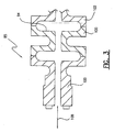
- the multi-element bellows structure 85 is shown in greater detail in Fig. 3.
- the bellows structure 85 includes several diaphragm elements 100,101,102, which are interconnected to one another to form the multi-element bellows structure 85.
- the bellows structure is made of a high strength, high temperature, and resiliently deformable material that may be easily machined, molded or formed, e.g., hydro-forming to the desired configuration.
- the elements 100,101,102 may be made of a machined titanium material.
- the bellows structure 85 is configured such that when the internal compartment 94 is sealed against external environmental pressure, for example as is accomplished in the pressure sensor configuration of Fig. 2, the bellows structure will expand and contract in an axial direction as illustrated by the line 108. This expansion and contraction is translated directly to the portion of the optical fiber containing the pressure sensing Bragg grating 47.
- the bellows structure is made from a high strength resiliently deformable material such as titanium, the material will need to be machined in order to arrive at the desired shape and therefore, the bellows is made in the several elements 100,101,102 as illustrated in Fig. 3 for ease of machining. These elements 100,101,102 ar then welded together.
- the bellows structure is made of material which can be formed by die cast molding, for example, then the bellows structure can be made into a single unit and not require individual elements.
- the sensitivity of the bellows structure 85 to changes in pressure in the environment is enhanced. That is, for a given pressure change in the environment, the change in axial length of the bellows structure is greater for each additional bellows segment of the overall bellows structure.
- any number of bellows elements may be used to form the bellows structure 85 of the invention, depending on the desired degree of sensitivity of the element.
- the invention is illustrated as using a bellows for transmitting the pressure of the environment to change the strain in the optical fiber
- various methods and structures of pressure translation can be utilized, for example, by utilizing a diaphragm such as the diaphragm illustrated in commonly owned PCT publication WO-A-98 31987.
- tubing delivery equipment for delivering the optical fiber 24 within the capillary tubing 31 down the borehole 3.
- the tubing delivery equipment provides for the delivery of the capillary tubing 31 and fiber 24 down the borehole 3, and for the delivery of optical signals between the optical signal processing equipment 18 and the fiber assembly 15, either directly or via interface equipment (not shown) as required.
- Fiber gratings are well suited for use as sensor elements. When a fiber grating is illuminated, it reflects a narrow band of light at a specified wavelength. However, a measurand, such as strain induced by pressure or temperature, will induce a change in the fiber grating spacing, which changes the wavelength of the light it reflects. The value (magnitude) of the measurand is directly related to the wavelength reflected by the fiber grating and can be determined by detecting the wavelength of the reflected light.
- the optical signal processing equipment 18 includes, at a minimum, the broadband source of light 49, such as the light emitting diode (LED), and appropriate equipment for delivery of signal light to the Bragg gratings 47,48 included within the core of the optical fiber 24. Additionally, the optical signal processing equipment 18 includes appropriate optical signal analysis equipment 50 for analyzing the return signals from the Bragg gratings 47,48.
- the broadband source of light 49 such as the light emitting diode (LED)
- LED light emitting diode
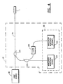
- Fig. 4 shows an arrangement for monitoring the wavelength shifts produced by the Bragg gratings 47, 48 to provide both static and dynamic pressure sensing. Additionally, the arrangement may also be used for monitoring wavelength shifts in a temperature measuring/compensation Bragg grating.
- Light from the broadband optical source 49 is coupled to the fiber 24 via a coupler 222.
- This coupler 222 directs light to the sensor assembly 1, and directs the reflected optical components from the Bragg gratings 47, 48 to the optical signal processing equipment 50 including wavelength monitoring sub-systems, 224 and 226.
- One of the wavelength monitoring systems 224 allows for the detection of wavelength shifts of the Bragg grating elements using an 'absolute' approach for static parameter monitoring (e.g. pressure & temperature).
- the other wavelength monitoring system 226 provides for detecting weak dynamically induced shifts for dynamic pressure monitoring.
- the returned optical components are directed into an optical wavelength analyzer 224, such as a scanning narrowband filter, which produces a measure of the Bragg wavelength of the signal light reflected by the Bragg grating 47.
- an optical wavelength analyzer 224 such as a scanning narrowband filter, which produces a measure of the Bragg wavelength of the signal light reflected by the Bragg grating 47.
- Static pressure can be deduced from the differential shift of the Bragg wavelengths produced by Bragg gratings 47.
- Temperature may be determined directly from a measure of the Bragg wavelength of the temperature compensation Bragg grating.
- a portion of the returned optical components is split off, using a coupler 223, to an alternative wavelength discriminator 226 to thereby provide high resolution monitoring of wavelength shifts.
- a portion of the returned optical components from the gratings are directed to a wavelength filter or router 225.
- This device separates the optical signals produced by each Bragg grating by means of selective filtering. The pass-bands of this device are wide enough to ensure that under normal operating conditions (full temperature & pressure range), the optical signal produced by a particular grating or gratings is always passed.
- the outputs of the router can then be analyzed using sensitive wavelength discriminators 226 to determine wavelength modulation effects due to dynamic pressure, associated for example with acoustic or seismic information.
- sensitive wavelength discriminators 226 By tuning the filter 225 passband, the separate gratings in the system can be analyzed individually.
- a wavelength division demultiplexer could be used to separate the wavelength components onto separate fibers that could then be each analyzed via separate high-resolution wavelength discriminators.
- An example of the type of wavelength discriminators suitable for this purpose is the interferometric detection approach described in U.S. Patent No. 5,361,130.
- optical signal processing equipment 50 Although a specific embodiment of the optical signal processing equipment 50 is described above, other optical signal analysis techniques may be used with the present invention such as the necessary hardware and software to implement the optical signal diagnostic equipment disclosed in U.S. Patent Nos. 4,996,419; 5,401,956; 5,426,297; and/or 5,493,390.
- the optical signal processing equipment may operate on a principle of wave-division multiplexing as described above wherein each Bragg grating sensor is utilized at a different passband or frequency band of interest.
- the present invention may utilize time-division multiplexing for obtaining signals from multiple independent sensors, or any other suitable means for analyzing signals returned from a plurality of Bragg grating sensors formed in a fiber optic sensor string.
- an input optical signal such as a broadband optical signal
- the broadband light source 49 is provided by the broadband light source 49 to the optical fiber 24.
- the optical signal travels along the optical fiber 24 to the sensor 1.
- the broadband light encounters the temperature sensing Bragg grating 48.
- each Bragg grating sensor is periodic refractive index variation in the core of an optical fiber that reflects a narrow wavelength of light, has a maximum reflectivity at a central reflectivity wavelength, and transmits all other wavelengths.
- the broadband light source signal is incident on the first (temperature sensing) Bragg grating sensor 48, a narrow wavelength band of light having a central wavelength ⁇ T is reflected therefrom, and light not reflected is transmitted through the grating 48 to the pressure sensing Bragg grating 47.
- the temperature sensing Bragg grating 47 reflects a narrow wavelength band of light having a central wavelength of ⁇ P .
- Light not reflected by the pressure sensing Bragg grating 47 is provided to the end of the optical fiber and is dispersed.
- the temperature sensing Bragg grating 48 will experience wavelength change (associated by change in strain) due to changes in temperature.
- the pressure sensing Bragg grating 47 will experience strain due to both changes in temperature and changes in the elongation of the bellows structure 85 (Fig. 2) associated with changes in the pressure in the environment. These strains will cause a wavelength shift in the central wavelength of the narrow band of light reflected by each Bragg grating sensor. For example, referring to Fig. 5, when the temperature sensing Bragg grating 48 is subject to a temperature strain, the central wavelength of reflected light ⁇ T shifts by an amount ⁇ T to a new central wavelength ⁇ T' .
- the Bragg grating sensors 47,48 are designed to provide a wavelength spacing such that when the central wavelength of one of the Bragg grating sensors shifts by a maximum amount, the central wavelength will still be in a desire bandwidth ⁇ which does not overlap with the bandwidth of any other Bragg grating sensor.
- Both of the Bragg grating sensors 47,48 are subject to the temperature of the environment, while only the pressure sensing Bragg grating 47 is subject to a change in strain associated with the pressure in the environment. Therefore, the temperature sensing Bragg grating 47 can be used to provide both a direct measurement of the temperature at the sensing location and to compensate for the wavelength shift in the pressure sensing Bragg grating 47 associated with temperature. Therefore, an accurate pressure measurement is provided. As will be understood by those skilled in the art, if it is desired to only instantaneous dynamic pressure, then temperature compensation is not required.
- a temperature compensated pressure sensor is described with respect to Fig. 2 as providing a temperature compensation Bragg grating 47 which is isolated from pressure strain so that it is only responsive to temperature changes.
- the temperature compensation Bragg grating may be made to be inversely responsive to pressure strain.
- a pressure sensing Bragg grating 147 is positioned within a bellows structure 185, in a similar manner as described with respect to the pressure sensing Bragg grating 47 of Fig. 2.
- a second, temperature compensation Bragg grating 148 is formed in the fiber 124 and is attached at an attachment point 149 to the bellows structure 185 on the opposite side as the pressure sensing Bragg grating 147.
- a portion of the fiber 150 on the side of the Bragg grating 148 opposite the mounting location 150 is fixed at a fixed reference location 151.
- the position of the fixed reference location 151 does not change with changes in pressure of the environment.
- the bellows structure must remain in communication with the environment in which pressure is sensed. Therefore, either the pressure reaches the bellows structure 185 via the end of the sensor, as described with respect to Fig. 2, or aperture must be formed in the sensor housing, for example as described with respect to Fig. 10.
- the strain in the two Bragg gratings change in an equal but opposite amount.
- the difference between the wavelength of the two Bragg grating sensors 147,148 will not change with temperature. Instead, the difference in the wavelength between the two Bragg grating sensors will only change due to pressure (causing a deflection in the position of the bellows 185).
- This configuration provides the significant advantages of inherent temperature compensation and enhanced pressure sensing.
- the change in central wavelength for the two Bragg grating sensors are subtracted from one another, the temperature component is canceled.
- the pressure component being equal and opposite, is doubled. Therefore, the system provides twice the wavelength shift for a given pressure change as compared to a sensor using a single Bragg grating.
- the Bragg grating sensors 147,148 are described as having an equal and opposite change in strain associated with change in pressure (causing a shift in the position of the bellows structure 185). This assumes that both Bragg gratings 147,148 are in a similar pre-strain, neutral strain or compression condition and that the sensors operate generally linearly with changes in strain. However, if the Bragg grating sensors 147,148 do not respond linearly over the desired operating region, the response of the Bragg gratings 147,148 can be characterized to thereby provide the desired temperature compensated pressure sensing in accordance with the invention.
- multiple pressure sensors constructed in accordance with the teachings of the invention may be multiplexed together to provide distributed pressure sensing.
- multiple pressure sensors 900, 901, 902 may be multiplexed together over a single optical fiber 924.
- one of the pressure sensors 900 is shown. This sensor is of the same basic structure as the pressure sensor 1 illustrated in Fig. 2. However, rather than terminating in a ferrule at the end of the bellows structure, the optical fiber 924 passes through a fitting 930 at the end of the bellows structure 985 for interconnection to the next pressure sensor 901.
- Both ends of the sensor 900 are interconnected to lengths of capillary tubing 935,936 to protect the optical fiber 924 along its length.
- the capillary tubing 935,936 may be connected to the sensor 900 by threads, welding, etc. for a secure, leak tight seal.
- the sensor When entering and exiting the capillary tubing 935, 936 on the ends of the sensor 900, the sensor is provided with pressure seals 955,956 to isolate the capillary tubes from the pressure sensor.
- Apertures 970 are provided in the sensor housing adjacent to the bellows structure 985 such that the bellows structure is exposed to the pressure in the environment.
- the various pressure and temperature signals from the different sensors 900, 901, 902 may be differentiated from one another using wavelength division multiplexing techniques.
- each Bragg grating is designed to operate at a central wavelength ⁇ within a bandwidth ⁇ that does not overlap with the bandwidth of the other Bragg grating sensors. Therefore, the temperature and pressure signals from each of the sensors 900,901,902 can be easily differentiated from one another based on the received wavelength.
- time division multiplexing techniques may be utilized to differentiate between signals from different Bragg grating sensors. As is known in the art, this well known technique is based on the position of each sensor along the length of the optical fiber 924 and the sequence that reflected signals will be received from each of the sensors.
- the multiplexed sensors 900, 901,902 of Fig. 9 may be of the type illustrated in Fig. 2, using an isolated temperature compensation Bragg grating sensor.
- the multiplexed sensors may be of the design illustrated in Fig. 6.
- the fixed reference location may be part of a pressure seal that isolates the pressure sensor from the capillary tube 936.
- an alternate embodiment of this invention can utilize a pair of reflective gratings within the same length of fiber, thus forming a resonant cavity of longer length.
- a resonant cavity will also reflect light of a particular wavelength corresponding to a central wavelength of the reflective gratings.
- a change in the cavity length due to a static strain, a dynamic strain and/or a temperature induced strain on fiber will result in phase shift in the reflected light due to the change in optical path length within the reflective cavity.
- Such a device termed a Fabry-Perot interferometer
- a Fabry-Perot interferometer can then provide a high sensitivity means of detecting strain in the optical fiber, and the resultant optical phase shift can be detected using standard interferometer instrumentation techniques.
- the pair of Bragg gratings may be used to form a lasing element for detection, for example by positioning an Erbium doped length of optical fiber between the pair of Bragg gratings.
Landscapes
- Physics & Mathematics (AREA)
- General Physics & Mathematics (AREA)
- Electromagnetism (AREA)
- Optics & Photonics (AREA)
- Measuring Fluid Pressure (AREA)
- Length Measuring Devices By Optical Means (AREA)
- Optical Transform (AREA)
Claims (14)
- Temperatur-kompensierter Drucksensor (1) zum Erfassen von Druck in einer Umgebung, umfassend:wobei das erste und zweite Bragg-Gitter-Sensorelement (148 und 147) auf ein optisches Eingangssignal und auf eine mechanische Spannung in Verbindung mit Änderungen in der dritten Anbringungsstellenposition ansprechen, um jeweils ein erstes optisches Erfassungssignal mit einer ersten Wellenlänge und ein zweites optisches Erfassungssignal mit einer zweiten Wellenlänge bereitzustellen, wobei die Differenz zwischen der ersten und zweiten Wellenlänge sich auf die Größe des Drucks der Umgebung bezieht.eine druckempfindliche Struktur mit wenigstens einer Dimension, die sich im Ansprechen auf Änderungen in dem Druck der Umgebung ändert, gekennzeichnet durch:eine optische Faser (124), die an der druckempfindlichen Struktur zwischen einer ersten Anbringungsstelle (151) und einer zweiten Anbringungsstelle (66), die beabstandet von der ersten Anbringungsstelle (151) ist, angebracht ist, wobei sowohl die erste als auch die zweite Anbringungsstelle Positionen aufweisen, die sich mit Änderungen in dem Druck der Umgebung nicht ändern, wobei die optische Faser auch an der druckempfindlichen Struktur an einer dritten Anbringungsstelle (149) zwischen der ersten und zweiten Anbringungsstelle angebracht ist, wobei die dritte Anbringungsstelle (149) eine Position aufweist, die sich mit Änderungen in der wenigstens einen Dimension verändert;ein erstes Bragg-Gitter-Sensorelement (148), das innerhalb der optischen Faser (124) zwischen der ersten und dritten Anbringungsstelle (151 und 149) positioniert ist; undein zweites Bragg-Gitter-Sensorelement (147), das innerhalb der optischen Faser (124) zwischen der zweiten und dritten Anbringungsstelle positioniert ist;
- Drucksensor nach Anspruch 1, dadurch gekennzeichnet, dass die druckempfindliche Struktur eine druckempfindliche Ausdehnungsmanschettenstruktur (185) einschließt, und dadurch gekennzeichnet, dass die wenigstens eine Dimension die axiale Länge der Ausdehnungsmanschettenstruktur (185) ist.
- Drucksensor nach Anspruch 1 oder 2, dadurch gekennzeichnet, dass dann, wenn sich die wenigstens eine Dimension im Ansprechen auf Änderungen in den Druck der Umgebung ändert, die mechanische Spannung in dem ersten und zweiten Bragg-Gitter-Sensorelement (148 und 147) sich in gleichen, aber entgegensetzten Beträgen, ändern.
- Drucksensor nach Anspruch 1, 2 oder 3, dadurch gekennzeichnet, dass das erste und zweite Bragg-Gitter-Sensorelement (148 und 147) unter einer anfänglichen Kompression angebracht sind, und dadurch gekennzeichnet, dass Änderungen in der wenigstens einen Dimension gleiche und entgegengesetzte Änderungen in der anfänglichen Kompression für das erste und zweite Bragg-Gitter-Sensorelement (148 und 147) verursachen.
- Drucksensor nach irgendeinem der Ansprüche 1 bis 3 dadurch gekennzeichnet, dass das erste und zweite Bragg-Gitter-Sensorelement (148 und 147) unter einer anfänglichen Spannung angebracht sind, und dadurch gekennzeichnet, dass Änderungen in der wenigstens einen Dimension gleiche und entgegengesetzte Änderungen in der anfänglichen Spannung für das erste und zweite Bragg-Gitter-Sensorelement (148 und 147) verursachen.
- Verteiltes Drucksensorsystem zum Erfassen eines Drucks an einer Vielzahl von Stellen in einer Umgebung, umfassend:eine Lichtquelle zum Bereitstellen eines optischen Eingangssignals;eine optische Faser, die mit der Lichtquelle gekoppelt ist; undeine Vielzahl von Drucksensoren, die entlang der optischen Faser beabstandet sind, dadurch gekennzeichnet, dass jeder Drucksensor ein Temperatur-kompensierter Drucksensor mit den Merkmalen von irgendeinem der Ansprüche 1 bis 5 ist.
- Verteiltes Drucksensorsystem nach Anspruch 6, ferner gekennzeichnet durch eine Faserträgereinrichtung, wobei die optische Faser (24) innerhalb der Faserträgereinrichtung (31) positioniert ist.
- Verteiltes Drucksensorsystem nach Anspruch 7, dadurch gekennzeichnet, dass die Faserträgereinrichtung (31) mit jedem der Sensoren (1) verbunden ist.
- Verteiltes Drucksensorsystem nach Anspruch 7 oder 8, dadurch gekennzeichnet, dass die Faserträgereinrichtung eine Vielzahl von Längen einer Kapillar-Röhrenverbindung (31) ist.
- Verteiltes Drucksensorsystem nach Anspruch 7, 8 oder 9, dadurch gekennzeichnet, dass die Faserträgereinrichtung (31) ein Beschichtungsmaterial einschließt, das die optische Faser (24) umgibt.
- Verteiltes Drucksensorsystem nach irgendeinem der Ansprüche 6 bis 10, dadurch gekennzeichnet, dass eine Zeitteilungsmultiplexierung (TDM) verwendet wird, um zwischen den optischen Erfassungssignalen von unterschiedlichen Bragg-Gitter-Erfassungseinrichtungen (47, 48) zu unterscheiden.
- Verteiltes Drucksensorsystem nach irgendeinem der Ansprüche 6 bis 11, dadurch gekennzeichnet, dass jede Bragg-Gitter-Erfassungseinrichtung (47, 48) eine jeweilige Bandbreite aufweist, die abgestimmt ist, um eine jeweilige Bandbreite von Licht zu reflektieren, wobei die jeweilige Bandbreite für jede Bragg-Gitter-Erfassungseinrichtung (47, 48) eine jeweilige zentrale Wellenlänge aufweist, wobei die jeweilige zentrale Wellenlänge für jede Bragg-Gitter-Erfassungseinrichtung (47, 48) unterschiedlich ist.
- Verteiltes Drucksensorsystem nach Anspruch 12, dadurch gekennzeichnet, dass eine Wellenlängenteilungsmultiplexierung (WDM) verwendet wird, um zwischen den optischen Erfassungssignalen von verschiedenen Bragg-Gitter-Erfassungseinrichtungen (47, 48) zu unterscheiden.
- Verteiltes Drucksensorsystem nach Anspruch 12, dadurch gekennzeichnet, dass eine Zeitteilungsmultiplexierung (TDM) und eine Wellenlängenteilungsmultiplexierung (WDM) verwendet wird, um zwischen den optischen Erfassungssignalen von unterschiedlichen Bragg-Gitter-Erfassungseinrichtungen (47, 48) zu unterscheiden.
Applications Claiming Priority (3)
| Application Number | Priority Date | Filing Date | Title |
|---|---|---|---|
| US925598 | 1997-09-08 | ||
| US08/925,598 US6016702A (en) | 1997-09-08 | 1997-09-08 | High sensitivity fiber optic pressure sensor for use in harsh environments |
| PCT/US1998/018065 WO1999013307A1 (en) | 1997-09-08 | 1998-09-01 | High sensitivity fiber optic pressure sensor for use in harsh environments |
Publications (2)
| Publication Number | Publication Date |
|---|---|
| EP1012553A1 EP1012553A1 (de) | 2000-06-28 |
| EP1012553B1 true EP1012553B1 (de) | 2003-11-12 |
Family
ID=25451980
Family Applications (1)
| Application Number | Title | Priority Date | Filing Date |
|---|---|---|---|
| EP98941114A Expired - Lifetime EP1012553B1 (de) | 1997-09-08 | 1998-09-01 | Hochempfindlicher faseroptischer drucksensor für rauhe umgebungen |
Country Status (7)
| Country | Link |
|---|---|
| US (1) | US6016702A (de) |
| EP (1) | EP1012553B1 (de) |
| AU (1) | AU8925198A (de) |
| CA (1) | CA2303257C (de) |
| DE (1) | DE69819754D1 (de) |
| NO (1) | NO322402B1 (de) |
| WO (1) | WO1999013307A1 (de) |
Cited By (1)
| Publication number | Priority date | Publication date | Assignee | Title |
|---|---|---|---|---|
| US8135245B2 (en) | 2008-12-05 | 2012-03-13 | General Electric Company | Fiber optic sensing system |
Families Citing this family (170)
| Publication number | Priority date | Publication date | Assignee | Title |
|---|---|---|---|---|
| US5832157A (en) * | 1996-07-12 | 1998-11-03 | Mcdermott Technology, Inc. | Fiber optic acoustic emission sensor |
| US6787758B2 (en) * | 2001-02-06 | 2004-09-07 | Baker Hughes Incorporated | Wellbores utilizing fiber optic-based sensors and operating devices |
| NO305004B1 (no) * | 1997-06-30 | 1999-03-15 | Optoplan As | Trykksensor |
| NO308050B1 (no) * | 1997-12-05 | 2000-07-10 | Optoplan As | Anordning for registrering av strekk |
| US6768825B2 (en) * | 1998-05-06 | 2004-07-27 | Weatherford/Lamb, Inc. | Optical sensor device having creep-resistant optical fiber attachments |
| EP1090274B1 (de) | 1998-06-26 | 2017-03-15 | Weatherford Technology Holdings, LLC | Flüssigkeitsparametermessung unter verwendung von akustischem druck |
| US6278811B1 (en) * | 1998-12-04 | 2001-08-21 | Arthur D. Hay | Fiber optic bragg grating pressure sensor |
| US6490931B1 (en) * | 1998-12-04 | 2002-12-10 | Weatherford/Lamb, Inc. | Fused tension-based fiber grating pressure sensor |
| US6621957B1 (en) | 2000-03-16 | 2003-09-16 | Cidra Corporation | Temperature compensated optical device |
| BE1012332A6 (nl) * | 1998-12-11 | 2000-09-05 | Voet Marc Rosa Henri | Optische druksensor en meetinrichting voorzien van dergelijke druksensor. |
| US6233746B1 (en) * | 1999-03-22 | 2001-05-22 | Halliburton Energy Services, Inc. | Multiplexed fiber optic transducer for use in a well and method |
| US6463813B1 (en) | 1999-06-25 | 2002-10-15 | Weatherford/Lamb, Inc. | Displacement based pressure sensor measuring unsteady pressure in a pipe |
| US6536291B1 (en) | 1999-07-02 | 2003-03-25 | Weatherford/Lamb, Inc. | Optical flow rate measurement using unsteady pressures |
| US7261002B1 (en) * | 1999-07-02 | 2007-08-28 | Cidra Corporation | Flow rate measurement for industrial sensing applications using unsteady pressures |
| US6691584B2 (en) | 1999-07-02 | 2004-02-17 | Weatherford/Lamb, Inc. | Flow rate measurement using unsteady pressures |
| DE19938978A1 (de) * | 1999-08-19 | 2001-02-22 | Abb Research Ltd | Faseroptischer Drucksensor |
| US6449402B1 (en) | 1999-11-19 | 2002-09-10 | Finisar Corporation | Method and apparatus for compensating an optical filter |
| JP3519333B2 (ja) * | 2000-02-10 | 2004-04-12 | エヌ・ティ・ティ・アドバンステクノロジ株式会社 | 光ファイバセンサ |
| US6813962B2 (en) * | 2000-03-07 | 2004-11-09 | Weatherford/Lamb, Inc. | Distributed sound speed measurements for multiphase flow measurement |
| US6601458B1 (en) | 2000-03-07 | 2003-08-05 | Weatherford/Lamb, Inc. | Distributed sound speed measurements for multiphase flow measurement |
| US6671055B1 (en) | 2000-04-13 | 2003-12-30 | Luna Innovations, Inc. | Interferometric sensors utilizing bulk sensing mediums extrinsic to the input/output optical fiber |
| EP1179727A1 (de) * | 2000-08-02 | 2002-02-13 | Abb Research Ltd. | Faser-Bragg-Gitter Sensor zur Druck- und Dichtemessung |
| NO315762B1 (no) * | 2000-09-12 | 2003-10-20 | Optoplan As | Sand-detektor |
| US6453108B1 (en) | 2000-09-30 | 2002-09-17 | Cidra Corporation | Athermal bragg grating package with course and fine mechanical tuning |
| US6782150B2 (en) | 2000-11-29 | 2004-08-24 | Weatherford/Lamb, Inc. | Apparatus for sensing fluid in a pipe |
| US6501067B2 (en) * | 2000-11-29 | 2002-12-31 | Weatherford/Lamb, Inc. | Isolation pad for protecting sensing devices on the outside of a conduit |
| DE10140482B4 (de) * | 2001-08-17 | 2008-11-13 | Siemens Ag | Verfahren und Vorrichtung zur Störgrößenkompensation eines optischen Sensors |
| US6971259B2 (en) * | 2001-11-07 | 2005-12-06 | Weatherford/Lamb, Inc. | Fluid density measurement in pipes using acoustic pressures |
| US7059172B2 (en) * | 2001-11-07 | 2006-06-13 | Weatherford/Lamb, Inc. | Phase flow measurement in pipes using a density meter |
| US6698297B2 (en) | 2002-06-28 | 2004-03-02 | Weatherford/Lamb, Inc. | Venturi augmented flow meter |
| US7032432B2 (en) * | 2002-01-23 | 2006-04-25 | Cidra Corporation | Apparatus and method for measuring parameters of a mixture having liquid droplets suspended in a vapor flowing in a pipe |
| US7359803B2 (en) * | 2002-01-23 | 2008-04-15 | Cidra Corporation | Apparatus and method for measuring parameters of a mixture having solid particles suspended in a fluid flowing in a pipe |
| US7328624B2 (en) * | 2002-01-23 | 2008-02-12 | Cidra Corporation | Probe for measuring parameters of a flowing fluid and/or multiphase mixture |
| US7275421B2 (en) * | 2002-01-23 | 2007-10-02 | Cidra Corporation | Apparatus and method for measuring parameters of a mixture having solid particles suspended in a fluid flowing in a pipe |
| US7474966B2 (en) * | 2002-01-23 | 2009-01-06 | Expro Meters. Inc | Apparatus having an array of piezoelectric film sensors for measuring parameters of a process flow within a pipe |
| US6848316B2 (en) * | 2002-05-08 | 2005-02-01 | Rosemount Inc. | Pressure sensor assembly |
| EP1523607B1 (de) * | 2002-07-23 | 2011-08-24 | Welldynamics, B.V. | Unterirdische bohrlochdruck- und temperaturmessung |
| US7181955B2 (en) * | 2002-08-08 | 2007-02-27 | Weatherford/Lamb, Inc. | Apparatus and method for measuring multi-Phase flows in pulp and paper industry applications |
| US6847034B2 (en) * | 2002-09-09 | 2005-01-25 | Halliburton Energy Services, Inc. | Downhole sensing with fiber in exterior annulus |
| US6978832B2 (en) | 2002-09-09 | 2005-12-27 | Halliburton Energy Services, Inc. | Downhole sensing with fiber in the formation |
| US20040065436A1 (en) * | 2002-10-03 | 2004-04-08 | Schultz Roger L. | System and method for monitoring a packer in a well |
| US20040065437A1 (en) * | 2002-10-06 | 2004-04-08 | Weatherford/Lamb Inc. | In-well seismic sensor casing coupling using natural forces in wells |
| CA2444379C (en) | 2002-10-06 | 2007-08-07 | Weatherford/Lamb, Inc. | Multiple component sensor mechanism |
| US7036601B2 (en) | 2002-10-06 | 2006-05-02 | Weatherford/Lamb, Inc. | Apparatus and method for transporting, deploying, and retrieving arrays having nodes interconnected by sections of cable |
| US6888972B2 (en) * | 2002-10-06 | 2005-05-03 | Weatherford/Lamb, Inc. | Multiple component sensor mechanism |
| US7400985B2 (en) * | 2002-11-12 | 2008-07-15 | Cidra Corporation | Apparatus having an array of clamp on piezoelectric film sensors for measuring parameters of a process flow within a pipe |
| US7165464B2 (en) * | 2002-11-15 | 2007-01-23 | Cidra Corporation | Apparatus and method for providing a flow measurement compensated for entrained gas |
| AU2003295992A1 (en) * | 2002-11-22 | 2004-06-18 | Cidra Corporation | Method for calibrating a flow meter having an array of sensors |
| WO2004063675A2 (en) * | 2003-01-13 | 2004-07-29 | Cidra Corporation | Apparatus and method using an array of ultrasonic sensors for determining the velocity of a fluid within a pipe |
| US7096719B2 (en) * | 2003-01-13 | 2006-08-29 | Cidra Corporation | Apparatus for measuring parameters of a flowing multiphase mixture |
| US7343818B2 (en) * | 2003-01-21 | 2008-03-18 | Cidra Corporation | Apparatus and method of measuring gas volume fraction of a fluid flowing within a pipe |
| ATE549603T1 (de) | 2003-01-21 | 2012-03-15 | Cidra Corporate Services Inc | Messung eingeschlossener und aufgelöster gase in prozessflussleitungen |
| US20060048583A1 (en) * | 2004-08-16 | 2006-03-09 | Gysling Daniel L | Total gas meter using speed of sound and velocity measurements |
| DE602004017571D1 (de) * | 2003-01-21 | 2008-12-18 | Expro Meters Inc | Vorrichtung und verfahren zur messung der gasvolumenfraktion eines in einem rohr strömenden fluids |
| WO2004065912A2 (en) * | 2003-01-21 | 2004-08-05 | Cidra Corporation | Apparatus and method for measuring unsteady pressures within a large diameter pipe |
| US6915686B2 (en) | 2003-02-11 | 2005-07-12 | Optoplan A.S. | Downhole sub for instrumentation |
| US7159653B2 (en) | 2003-02-27 | 2007-01-09 | Weatherford/Lamb, Inc. | Spacer sub |
| WO2004079306A1 (en) | 2003-03-04 | 2004-09-16 | Cidra Corporation | An apparatus having a multi-band sensor assembly for measuring a parameter of a fluid flow flowing within a pipe |
| US6986276B2 (en) * | 2003-03-07 | 2006-01-17 | Weatherford/Lamb, Inc. | Deployable mandrel for downhole measurements |
| US6837098B2 (en) * | 2003-03-19 | 2005-01-04 | Weatherford/Lamb, Inc. | Sand monitoring within wells using acoustic arrays |
| US6957574B2 (en) * | 2003-05-19 | 2005-10-25 | Weatherford/Lamb, Inc. | Well integrity monitoring system |
| US6840114B2 (en) * | 2003-05-19 | 2005-01-11 | Weatherford/Lamb, Inc. | Housing on the exterior of a well casing for optical fiber sensors |
| WO2004109239A2 (en) * | 2003-06-05 | 2004-12-16 | Cidra Corporation | Apparatus for measuring velocity and flow rate of a fluid having a non-negligible axial mach number using an array of sensors |
| EP1644705B1 (de) * | 2003-06-24 | 2016-10-12 | Cidra Corporate Services, Inc. | System und verfahren zum betreiben eines flussprozesses |
| US7299705B2 (en) * | 2003-07-15 | 2007-11-27 | Cidra Corporation | Apparatus and method for augmenting a Coriolis meter |
| CA2532468C (en) | 2003-07-15 | 2013-04-23 | Cidra Corporation | A dual function flow measurement apparatus having an array of sensors |
| US7134320B2 (en) * | 2003-07-15 | 2006-11-14 | Cidra Corporation | Apparatus and method for providing a density measurement augmented for entrained gas |
| EP1646849B1 (de) * | 2003-07-15 | 2008-11-12 | Expro Meters, Inc. | Apparat und verfahren zur kompensation eines coriolis-durchflussmessers |
| WO2005015135A2 (en) * | 2003-08-08 | 2005-02-17 | Cidra Corporation | Piezocable based sensor for measuring unsteady pressures inside a pipe |
| US6910388B2 (en) * | 2003-08-22 | 2005-06-28 | Weatherford/Lamb, Inc. | Flow meter using an expanded tube section and sensitive differential pressure measurement |
| US20080264182A1 (en) * | 2003-08-22 | 2008-10-30 | Jones Richard T | Flow meter using sensitive differential pressure measurement |
| US6945117B2 (en) * | 2003-08-29 | 2005-09-20 | Dana Corporation | Gasket having a fiber-optic pressure sensor assembly |
| US7104141B2 (en) * | 2003-09-04 | 2006-09-12 | Baker Hughes Incorporated | Optical sensor with co-located pressure and temperature sensors |
| EP1942324B1 (de) * | 2003-09-04 | 2012-04-11 | Baker Hughes Incorporated | Optischer Sensor mit benachbarten Druck- und Temperaturfühlern |
| EP1664706B1 (de) * | 2003-09-04 | 2011-07-27 | Baker Hughes Incorporated | Optischer sensor mit colokalisierten druck- und temperatursensoren |
| US7237440B2 (en) * | 2003-10-10 | 2007-07-03 | Cidra Corporation | Flow measurement apparatus having strain-based sensors and ultrasonic sensors |
| US7050662B2 (en) * | 2003-11-19 | 2006-05-23 | Em Photonics, Inc. | Fiber Bragg grating compression sensor system |
| US7367239B2 (en) * | 2004-03-23 | 2008-05-06 | Cidra Corporation | Piezocable based sensor for measuring unsteady pressures inside a pipe |
| US7492463B2 (en) | 2004-04-15 | 2009-02-17 | Davidson Instruments Inc. | Method and apparatus for continuous readout of Fabry-Perot fiber optic sensor |
| US7426852B1 (en) | 2004-04-26 | 2008-09-23 | Expro Meters, Inc. | Submersible meter for measuring a parameter of gas hold-up of a fluid |
| US7480056B2 (en) * | 2004-06-04 | 2009-01-20 | Optoplan As | Multi-pulse heterodyne sub-carrier interrogation of interferometric sensors |
| US7109471B2 (en) * | 2004-06-04 | 2006-09-19 | Weatherford/Lamb, Inc. | Optical wavelength determination using multiple measurable features |
| US7159468B2 (en) * | 2004-06-15 | 2007-01-09 | Halliburton Energy Services, Inc. | Fiber optic differential pressure sensor |
| US7196318B2 (en) * | 2004-07-16 | 2007-03-27 | Kin-Man Yip | Fiber-optic sensing system |
| BRPI0403240B1 (pt) * | 2004-08-10 | 2016-02-16 | Petroleo Brasileiro Sa | transdutor óptico para medida simultânea de pressão e temperatura em poços de petróleo e método para dita medida |
| BRPI0403786A (pt) * | 2004-09-09 | 2006-05-02 | Petroleo Brasileiro Sa | transdutor de pressão diferencial a fibra óptica |
| WO2006112878A2 (en) | 2004-09-16 | 2006-10-26 | Cidra Corporation | Apparatus and method for providing a fluid cut measurement of a multi-liquid mixture compensated for entrained gas |
| US7389687B2 (en) * | 2004-11-05 | 2008-06-24 | Cidra Corporation | System for measuring a parameter of an aerated multi-phase mixture flowing in a pipe |
| US7311150B2 (en) * | 2004-12-21 | 2007-12-25 | Cdx Gas, Llc | Method and system for cleaning a well bore |
| EP1681540A1 (de) * | 2004-12-21 | 2006-07-19 | Davidson Instruments, Inc. | Mehrkanalarrayprozessor |
| EP1674833A3 (de) * | 2004-12-21 | 2007-05-30 | Davidson Instruments, Inc. | Faseroptisches Sensorsystem |
| US7302123B2 (en) * | 2005-03-10 | 2007-11-27 | Weatherford/Lamb, Inc. | Dynamic optical waveguide sensor |
| EP1869737B1 (de) * | 2005-03-16 | 2021-05-12 | Davidson Instruments, Inc. | Hochintensitäts-fabry-perot-sensor |
| US7657392B2 (en) * | 2005-05-16 | 2010-02-02 | Cidra Corporate Services, Inc. | Method and apparatus for detecting and characterizing particles in a multiphase fluid |
| US7526966B2 (en) | 2005-05-27 | 2009-05-05 | Expro Meters, Inc. | Apparatus and method for measuring a parameter of a multiphase flow |
| MX2007014705A (es) | 2005-05-27 | 2008-02-15 | Cidra Corp | Un aparato y metodo para medir un parametro de un flujo de fases multiples. |
| US7500793B2 (en) * | 2005-05-31 | 2009-03-10 | Greene, Tweed Of Delaware, Inc. | High-pressure/high-temperature seals between glass fibers and metals, downhole optical feedthroughs containing the same, and methods of preparing such seals |
| US7249525B1 (en) | 2005-06-22 | 2007-07-31 | Cidra Corporation | Apparatus for measuring parameters of a fluid in a lined pipe |
| EP1899686B1 (de) | 2005-07-07 | 2011-09-28 | CiDra Corporation | Feuchtgasmessung unter verwendung eines differentialdruckbasierten durchflussmeters mit einem sonarbasierten durchflussmeter |
| WO2007009097A1 (en) * | 2005-07-13 | 2007-01-18 | Cidra Corporation | Method and apparatus for measuring parameters of a fluid flow using an array of sensors |
| WO2007022492A1 (en) * | 2005-08-17 | 2007-02-22 | Cidra Corporation | A system and method for providing a compositional measurement of a mixture having entrained gas |
| WO2007033069A2 (en) * | 2005-09-13 | 2007-03-22 | Davidson Instruments Inc. | Tracking algorithm for linear array signal processor for fabry-perot cross-correlation pattern and method of using same |
| US7503217B2 (en) | 2006-01-27 | 2009-03-17 | Weatherford/Lamb, Inc. | Sonar sand detection |
| US20070252998A1 (en) * | 2006-03-22 | 2007-11-01 | Berthold John W | Apparatus for continuous readout of fabry-perot fiber optic sensor |
| US7684051B2 (en) * | 2006-04-18 | 2010-03-23 | Halliburton Energy Services, Inc. | Fiber optic seismic sensor based on MEMS cantilever |
| EP2021747B1 (de) * | 2006-04-26 | 2018-08-01 | Halliburton Energy Services, Inc. | Faseroptischer seismischer mems-sensor mit von schwenkbalken getragener masse |
| WO2007149733A2 (en) * | 2006-06-19 | 2007-12-27 | Baker Hughes Incorporated | Isolated sensor housing |
| US7624650B2 (en) | 2006-07-27 | 2009-12-01 | Expro Meters, Inc. | Apparatus and method for attenuating acoustic waves propagating within a pipe wall |
| US8115937B2 (en) * | 2006-08-16 | 2012-02-14 | Davidson Instruments | Methods and apparatus for measuring multiple Fabry-Perot gaps |
| US7539361B2 (en) | 2006-10-05 | 2009-05-26 | Harris Corporation | Fiber optic device for measuring a parameter of interest |
| US7624651B2 (en) * | 2006-10-30 | 2009-12-01 | Expro Meters, Inc. | Apparatus and method for attenuating acoustic waves in pipe walls for clamp-on ultrasonic flow meter |
| US7673526B2 (en) * | 2006-11-01 | 2010-03-09 | Expro Meters, Inc. | Apparatus and method of lensing an ultrasonic beam for an ultrasonic flow meter |
| NO345532B1 (no) | 2006-11-09 | 2021-03-29 | Expro Meters Inc | Apparat og fremgangsmåte for måling av en fluidstrømparameter innenfor en intern passasje i et langstrakt legme |
| US7840102B2 (en) * | 2007-01-16 | 2010-11-23 | Baker Hughes Incorporated | Distributed optical pressure and temperature sensors |
| US8417084B2 (en) * | 2007-01-16 | 2013-04-09 | Baker Hughes Incorporated | Distributed optical pressure and temperature sensors |
| WO2008091645A1 (en) * | 2007-01-24 | 2008-07-31 | Davidson Energy | Transducer for measuring environmental parameters |
| US7817285B2 (en) * | 2007-10-11 | 2010-10-19 | Baker Hughes Incorporated | Downhole uses of pressure-tuned semiconductor light sources |
| SA08290691B1 (ar) * | 2007-10-31 | 2012-02-22 | شل انترناشيونال ريسيرش ماتشابيج بى . فى | تجميعة جهاز استشعار ضغط وطريقة لاستخدام التجميعة |
| US8061186B2 (en) | 2008-03-26 | 2011-11-22 | Expro Meters, Inc. | System and method for providing a compositional measurement of a mixture having entrained gas |
| US7637167B2 (en) | 2008-04-25 | 2009-12-29 | Schlumberger Technology Corporation | Apparatus and method for characterizing two phase fluid flow |
| US9347312B2 (en) | 2009-04-22 | 2016-05-24 | Weatherford Canada Partnership | Pressure sensor arrangement using an optical fiber and methodologies for performing an analysis of a subterranean formation |
| US8547426B2 (en) * | 2009-06-15 | 2013-10-01 | Identix Incorporated | Low settle time micro-scanning system |
| US8151648B2 (en) * | 2009-08-03 | 2012-04-10 | University Of Maryland | Ultra-miniature fiber-optic pressure sensor system and method of fabrication |
| US11639862B1 (en) * | 2009-09-15 | 2023-05-02 | Astro Technology Group, Llc | Apparatus, system and method enabling multiplexed arrangement of optical fiber for sensing of operating conditions within a structural member |
| US11519802B1 (en) * | 2009-09-15 | 2022-12-06 | Astro Technology Group, Llc | Apparatus, fiber optic sensor assembly and sensor housing assembly utilizing viscous material composition to mitigate signal attenuation |
| WO2011042023A1 (en) * | 2009-10-05 | 2011-04-14 | Nkt Flexibles I/S | A flexible unbonded oil pipe system with an optical fiber sensor inside |
| US20110133067A1 (en) * | 2009-12-08 | 2011-06-09 | Schlumberger Technology Corporation | Optical sensor having a capillary tube and an optical fiber in the capillary tube |
| US8966988B2 (en) | 2010-08-03 | 2015-03-03 | University Of Maryland | Ultra-miniature fiber-optic pressure sensor system and method of fabrication |
| US9194973B2 (en) | 2010-12-03 | 2015-11-24 | Baker Hughes Incorporated | Self adaptive two dimensional filter for distributed sensing data |
| US9557239B2 (en) | 2010-12-03 | 2017-01-31 | Baker Hughes Incorporated | Determination of strain components for different deformation modes using a filter |
| US9103736B2 (en) | 2010-12-03 | 2015-08-11 | Baker Hughes Incorporated | Modeling an interpretation of real time compaction modeling data from multi-section monitoring system |
| US20120200422A1 (en) * | 2011-02-09 | 2012-08-09 | Baker Hughes Incorporated | Use of Digital Transport Delay to Improve Measurement Fidelity in Swept-Wavelength Systems |
| US20130094812A1 (en) * | 2011-10-12 | 2013-04-18 | Baker Hughes Incorporated | Conduit Tube Assembly and Manufacturing Method for Subterranean Use |
| US8590385B2 (en) * | 2011-12-12 | 2013-11-26 | General Electric Company | High pressure fiber optic sensor system |
| CN102589585B (zh) * | 2012-01-11 | 2014-12-17 | 哈尔滨工业大学深圳研究生院 | 一种线性腔内光纤布拉格光栅阵列传感系统 |
| GB2500255B (en) | 2012-03-16 | 2020-04-15 | Oxsensis Ltd | Optical sensor |
| CN102724335B (zh) * | 2012-04-16 | 2015-06-03 | 中兴通讯股份有限公司 | 防水装置 |
| GB2507666B (en) * | 2012-11-02 | 2017-08-16 | Silixa Ltd | Determining a profile of fluid type in a well by distributed acoustic sensing |
| US9632071B2 (en) | 2013-07-25 | 2017-04-25 | General Electric Company | Systems and methods for analyzing a multiphase fluid |
| US9103704B2 (en) | 2013-07-25 | 2015-08-11 | General Electric Company | Holding device to hold a reflector and an electromagnetic guiding device |
| CA2916266C (en) * | 2013-08-09 | 2018-11-27 | Halliburton Energy Services, Inc. | Improved optical fiber feedthrough incorporating fiber bragg grating |
| US9410422B2 (en) | 2013-09-13 | 2016-08-09 | Chevron U.S.A. Inc. | Alternative gauging system for production well testing and related methods |
| US9605534B2 (en) | 2013-11-13 | 2017-03-28 | Baker Hughes Incorporated | Real-time flow injection monitoring using distributed Bragg grating |
| DE102014103721A1 (de) * | 2013-12-20 | 2015-06-25 | Endress + Hauser Conducta Gesellschaft für Mess- und Regeltechnik mbH + Co. KG | Optischer Sensor, insbesondere zur Bestimmung von Stoffkonzentrationen in wässrigen Lösungen mittels einer Chemilumineszenz-, Absorptions- oder Fluoreszenzmessung |
| US9341532B2 (en) | 2014-03-24 | 2016-05-17 | General Electric Company | Systems and methods for distributed pressure sensing |
| US10161924B2 (en) * | 2014-03-24 | 2018-12-25 | National Technology & Engineering Solutions Of Sandia, Llc | Sensor system that uses embedded optical fibers |
| CA3012210A1 (en) | 2014-05-08 | 2015-11-12 | WellGauge, Inc. | Well water depth monitor |
| US9240262B1 (en) | 2014-07-21 | 2016-01-19 | General Electric Company | Systems and methods for distributed pressure sensing |
| CN106796141B (zh) | 2014-08-26 | 2019-04-23 | 西门子公司 | 用于燃气涡轮发动机中的光学传感器的密封系统 |
| CN104612665B (zh) * | 2014-12-31 | 2017-07-28 | 哈尔滨工业大学 | 三膜两放高压光纤压力传感器及采用该传感器实现井下管道压力的测量方法 |
| US10133017B2 (en) * | 2015-08-07 | 2018-11-20 | Pgs Geophysical As | Vented optical tube |
| NL2015952B1 (en) * | 2015-12-11 | 2017-07-03 | Fugro Tech Bv | Pressure sensor and sensor system comprising one or more pressure sensors. |
| US10370956B2 (en) * | 2016-02-18 | 2019-08-06 | Weatherford Technology Holdings, Llc | Pressure gauge insensitive to extraneous mechanical loadings |
| CN105890679B (zh) * | 2016-06-20 | 2019-11-22 | 天津大学 | 局部弯曲导流的光纤法珀式流量测试方法 |
| NL2017916B1 (en) | 2016-12-02 | 2018-06-18 | Fugro Tech Bv | Embankment monitoring system |
| US10288559B2 (en) | 2017-03-03 | 2019-05-14 | Honeywell International Inc. | Gas concentration sensor with improved accuracy |
| US10748702B2 (en) * | 2017-04-28 | 2020-08-18 | Abb Power Grids Switzerland Ag | Transformer system and system for measuring pressure in a transformer tank |
| US10859411B2 (en) * | 2017-06-12 | 2020-12-08 | Advanced Opto-Mechanical Systems And Technologies Inc. | Multi-parameter distributed fiber optic sensor system and methods of sensor manufacturing |
| CN107356356A (zh) * | 2017-06-27 | 2017-11-17 | 中国科学院武汉岩土力学研究所 | 一种高成活率的光纤光栅围岩应力监测装置及监测系统 |
| RU2655471C1 (ru) * | 2017-08-11 | 2018-05-28 | Федеральное государственное унитарное предприятие "Всероссийский научно-исследовательский институт автоматики им. Н.Л. Духова" (ФГУП "ВНИИА") | Способ повышения спектральной чувствительности брэгговского преобразователя деформации балочного типа |
| CN107941306B (zh) * | 2017-12-21 | 2023-09-05 | 珠海任驰光电科技有限公司 | 一种改进型双光纤光栅封装的液位传感器及液位测量方法 |
| WO2019237170A1 (pt) * | 2018-06-11 | 2019-12-19 | Faculdades Católicas | Conjunto e método para medição da vazão de fluido em tubulações |
| CN110017938A (zh) * | 2019-03-20 | 2019-07-16 | 常州天利智能控制股份有限公司 | 一种波纹管式压力传感器及具有其的自动控制器 |
| CN111076854B (zh) * | 2020-02-24 | 2024-06-11 | 天津师范大学 | 用于波浪载荷作用下船体结构压力监测的光纤光栅传感器及应用 |
| US11585712B2 (en) | 2020-08-21 | 2023-02-21 | Simmonds Precision Products, Inc. | Fiber optic load sensors and systems therefor |
| CN112833950B (zh) * | 2021-01-07 | 2023-05-23 | 中国舰船研究设计中心 | 基于光纤传感的蒸汽管道内部复杂流场分布式测量系统 |
| CN112964299B (zh) * | 2021-02-09 | 2022-10-25 | 中北大学 | 耐高温高压结构热-声-振三参数集成原位传感器及系统 |
| CN114858216B (zh) * | 2022-05-07 | 2023-09-12 | 河北地质大学 | 一种基于光纤传感技术的地质灾害监测系统 |
| CN116735445B (zh) * | 2023-06-27 | 2024-04-12 | 华北科技学院(中国煤矿安全技术培训中心) | 一种用于监测油液污染度的光纤光栅传感器 |
| CN119984609A (zh) * | 2025-04-17 | 2025-05-13 | 洛阳仁晟石化工程技术有限公司 | 压力容器高温环境下的应力分布测量机构及其使用方法 |
Citations (1)
| Publication number | Priority date | Publication date | Assignee | Title |
|---|---|---|---|---|
| US4806012A (en) * | 1984-08-13 | 1989-02-21 | United Technologies Corporation | Distributed, spatially resolving optical fiber strain gauge |
Family Cites Families (38)
| Publication number | Priority date | Publication date | Assignee | Title |
|---|---|---|---|---|
| US5363463A (en) * | 1982-08-06 | 1994-11-08 | Kleinerman Marcos Y | Remote sensing of physical variables with fiber optic systems |
| US4509370A (en) * | 1982-09-30 | 1985-04-09 | Regents Of The University Of California | Pressure-sensitive optrode |
| US4545253A (en) * | 1983-08-29 | 1985-10-08 | Exxon Production Research Co. | Fiber optical modulator and data multiplexer |
| US4577100A (en) * | 1983-12-27 | 1986-03-18 | United Technologies Corporation | Temperature compensated optical pressure sensor |
| US4589285A (en) * | 1984-11-05 | 1986-05-20 | Western Geophysical Co. Of America | Wavelength-division-multiplexed receiver array for vertical seismic profiling |
| JPS61277028A (ja) * | 1985-05-31 | 1986-12-08 | Sumitomo Electric Ind Ltd | センサ− |
| US4649529A (en) * | 1985-12-02 | 1987-03-10 | Exxon Production Research Co. | Multi-channel fiber optic sensor system |
| EP0227556A1 (de) * | 1985-12-24 | 1987-07-01 | Schlumberger Industries | Optischer Sensor für physikalische Grössen |
| US4859844A (en) * | 1988-02-24 | 1989-08-22 | Hughes Aircraft Company | Comb filter pressure/temperature sensing system |
| US4900937A (en) * | 1988-10-20 | 1990-02-13 | Bicron Corporation | Well logging detector with decoupling optical interface |
| US5012090A (en) * | 1989-02-09 | 1991-04-30 | Simmonds Precision Products, Inc. | Optical grating sensor and method of monitoring having a multi-period grating |
| IT1237486B (it) * | 1989-06-23 | 1993-06-07 | Agip Spa | Procedimento e dispositivo a sensori interferometrici a fibra ottica per l'analisi della deformazione dinamica di una struttura o di suoi componenti |
| US4932262A (en) * | 1989-06-26 | 1990-06-12 | General Motors Corporation | Miniature fiber optic pressure sensor |
| US4932263A (en) * | 1989-06-26 | 1990-06-12 | General Motors Corporation | Temperature compensated fiber optic pressure sensor |
| US5163321A (en) * | 1989-10-17 | 1992-11-17 | Baroid Technology, Inc. | Borehole pressure and temperature measurement system |
| US4996419A (en) * | 1989-12-26 | 1991-02-26 | United Technologies Corporation | Distributed multiplexed optical fiber Bragg grating sensor arrangeement |
| US5042898A (en) * | 1989-12-26 | 1991-08-27 | United Technologies Corporation | Incorporated Bragg filter temperature compensated optical waveguide device |
| DE4037077A1 (de) * | 1990-11-22 | 1992-05-27 | Hilti Ag | Verfahren und einrichtung zur faseroptischen kraftmessung |
| US5144690A (en) * | 1990-12-03 | 1992-09-01 | Corning Incorporated | Optical fiber sensor with localized sensing regions |
| US5485745A (en) * | 1991-05-20 | 1996-01-23 | Halliburton Company | Modular downhole inspection system for coiled tubing |
| US5499533A (en) * | 1992-08-26 | 1996-03-19 | Miller; Mark | Downhole pressure gauge converter |
| DE69314289T2 (de) * | 1992-12-07 | 1998-01-29 | Akishima Lab Mitsui Zosen Inc | System für Messungen während des Bohrens mit Druckpuls-Ventil zur Datenübertragung |
| US5414507A (en) * | 1993-04-01 | 1995-05-09 | Hughes Aircraft Company | Fiber optics pressure sensor transducer having a temperature compensator |
| KR960007884B1 (ko) * | 1993-04-24 | 1996-06-15 | 국방과학연구소 | 광섬유 격자를 이용한 광섬유소자 |
| US5357806A (en) * | 1993-05-03 | 1994-10-25 | Halliburton Company | Capacitive differential pressure sensor and method of measuring differential pressure at an oil or gas well |
| US5315110A (en) * | 1993-06-29 | 1994-05-24 | Abb Vetco Gray Inc. | Metal cup pressure transducer with a support having a plurality of thermal expansion coefficients |
| US5351324A (en) * | 1993-09-10 | 1994-09-27 | The Regents Of The University Of California, Office Of Technology Transfer | Fiber optic security seal including plural Bragg gratings |
| US5401956A (en) * | 1993-09-29 | 1995-03-28 | United Technologies Corporation | Diagnostic system for fiber grating sensors |
| US5452087A (en) * | 1993-11-04 | 1995-09-19 | The Texas A & M University System | Method and apparatus for measuring pressure with embedded non-intrusive fiber optics |
| US5548116A (en) * | 1994-03-01 | 1996-08-20 | Optoscint, Inc. | Long life oil well logging assembly |
| US5399854A (en) * | 1994-03-08 | 1995-03-21 | United Technologies Corporation | Embedded optical sensor capable of strain and temperature measurement using a single diffraction grating |
| AUPM547194A0 (en) * | 1994-05-06 | 1994-06-02 | University Of Sydney, The | Variable property light transmitting device |
| EP0713077B1 (de) * | 1994-11-17 | 1999-12-15 | Alcatel | Verfahren zum Messen und Detektieren physikalischer Grössen unter Verwendung eines Mehrpunktsensors |
| US5675674A (en) * | 1995-08-24 | 1997-10-07 | Rockbit International | Optical fiber modulation and demodulation system |
| US5646401A (en) * | 1995-12-22 | 1997-07-08 | Udd; Eric | Fiber optic grating and etalon sensor systems |
| US5633748A (en) * | 1996-03-05 | 1997-05-27 | The United States Of America As Represented By The Secretary Of The Navy | Fiber optic Bragg grating demodulator and sensor incorporating same |
| US5680489A (en) * | 1996-06-28 | 1997-10-21 | The United States Of America As Represented By The Secretary Of The Navy | Optical sensor system utilizing bragg grating sensors |
| US5767411A (en) * | 1996-12-31 | 1998-06-16 | Cidra Corporation | Apparatus for enhancing strain in intrinsic fiber optic sensors and packaging same for harsh environments |
-
1997
- 1997-09-08 US US08/925,598 patent/US6016702A/en not_active Expired - Lifetime
-
1998
- 1998-09-01 WO PCT/US1998/018065 patent/WO1999013307A1/en not_active Ceased
- 1998-09-01 DE DE69819754T patent/DE69819754D1/de not_active Expired - Lifetime
- 1998-09-01 EP EP98941114A patent/EP1012553B1/de not_active Expired - Lifetime
- 1998-09-01 CA CA002303257A patent/CA2303257C/en not_active Expired - Fee Related
- 1998-09-01 AU AU89251/98A patent/AU8925198A/en not_active Abandoned
-
2000
- 2000-03-07 NO NO20001161A patent/NO322402B1/no not_active IP Right Cessation
Patent Citations (1)
| Publication number | Priority date | Publication date | Assignee | Title |
|---|---|---|---|---|
| US4806012A (en) * | 1984-08-13 | 1989-02-21 | United Technologies Corporation | Distributed, spatially resolving optical fiber strain gauge |
Cited By (1)
| Publication number | Priority date | Publication date | Assignee | Title |
|---|---|---|---|---|
| US8135245B2 (en) | 2008-12-05 | 2012-03-13 | General Electric Company | Fiber optic sensing system |
Also Published As
| Publication number | Publication date |
|---|---|
| CA2303257C (en) | 2005-05-10 |
| DE69819754D1 (de) | 2003-12-18 |
| NO20001161L (no) | 2000-05-08 |
| AU8925198A (en) | 1999-03-29 |
| CA2303257A1 (en) | 1999-03-18 |
| WO1999013307A1 (en) | 1999-03-18 |
| NO20001161D0 (no) | 2000-03-07 |
| US6016702A (en) | 2000-01-25 |
| NO322402B1 (no) | 2006-10-02 |
| EP1012553A1 (de) | 2000-06-28 |
Similar Documents
| Publication | Publication Date | Title |
|---|---|---|
| EP1012553B1 (de) | Hochempfindlicher faseroptischer drucksensor für rauhe umgebungen | |
| US5892860A (en) | Multi-parameter fiber optic sensor for use in harsh environments | |
| US6072567A (en) | Vertical seismic profiling system having vertical seismic profiling optical signal processing equipment and fiber Bragg grafting optical sensors | |
| US5844667A (en) | Fiber optic pressure sensor with passive temperature compensation | |
| US5877426A (en) | Bourdon tube pressure gauge with integral optical strain sensors for measuring tension or compressive strain | |
| US6137621A (en) | Acoustic logging system using fiber optics | |
| EP0950170B1 (de) | Anordnung zur erhöhung der mechanischen spannung in inneren faseroptischen sensoren und aufbau für rauhe umgebengen | |
| US6959604B2 (en) | Apparatus and method having an optical fiber disposed circumferentially around the pipe for measuring unsteady pressure within a pipe | |
| US6450037B1 (en) | Non-intrusive fiber optic pressure sensor for measuring unsteady pressures within a pipe | |
| US6955085B2 (en) | Optical accelerometer or displacement device using a flexure system | |
| US6233746B1 (en) | Multiplexed fiber optic transducer for use in a well and method | |
| CA2309620C (en) | Coiled tubing sensor system for delivery of distributed multiplexed sensors | |
| US5925879A (en) | Oil and gas well packer having fiber optic Bragg Grating sensors for downhole insitu inflation monitoring | |
| CA2874263C (en) | Array temperature sensing method and system | |
| US20020196993A1 (en) | Fiber optic supported sensor-telemetry system | |
| EP1110065B1 (de) | Seismisches mess-system und akustisches bohrlochsystem mit optischer faser, wandlern und sensoren | |
| EP1332337B1 (de) | Multiparameter interferometrischer glasfasersensor | |
| Kersey et al. | MONITORING TECHNIQUES |
Legal Events
| Date | Code | Title | Description |
|---|---|---|---|
| PUAI | Public reference made under article 153(3) epc to a published international application that has entered the european phase |
Free format text: ORIGINAL CODE: 0009012 |
|
| 17P | Request for examination filed |
Effective date: 20000410 |
|
| AK | Designated contracting states |
Kind code of ref document: A1 Designated state(s): DE FR GB |
|
| 17Q | First examination report despatched |
Effective date: 20010412 |
|
| GRAH | Despatch of communication of intention to grant a patent |
Free format text: ORIGINAL CODE: EPIDOS IGRA |
|
| GRAS | Grant fee paid |
Free format text: ORIGINAL CODE: EPIDOSNIGR3 |
|
| RAP1 | Party data changed (applicant data changed or rights of an application transferred) |
Owner name: WEATHERFORD/LAMB, INC. |
|
| GRAA | (expected) grant |
Free format text: ORIGINAL CODE: 0009210 |
|
| AK | Designated contracting states |
Kind code of ref document: B1 Designated state(s): DE FR GB |
|
| PG25 | Lapsed in a contracting state [announced via postgrant information from national office to epo] |
Ref country code: FR Free format text: LAPSE BECAUSE OF FAILURE TO SUBMIT A TRANSLATION OF THE DESCRIPTION OR TO PAY THE FEE WITHIN THE PRESCRIBED TIME-LIMIT Effective date: 20031112 |
|
| REG | Reference to a national code |
Ref country code: GB Ref legal event code: FG4D |
|
| REF | Corresponds to: |
Ref document number: 69819754 Country of ref document: DE Date of ref document: 20031218 Kind code of ref document: P |
|
| PG25 | Lapsed in a contracting state [announced via postgrant information from national office to epo] |
Ref country code: DE Free format text: LAPSE BECAUSE OF FAILURE TO SUBMIT A TRANSLATION OF THE DESCRIPTION OR TO PAY THE FEE WITHIN THE PRESCRIBED TIME-LIMIT Effective date: 20040213 |
|
| PLBE | No opposition filed within time limit |
Free format text: ORIGINAL CODE: 0009261 |
|
| STAA | Information on the status of an ep patent application or granted ep patent |
Free format text: STATUS: NO OPPOSITION FILED WITHIN TIME LIMIT |
|
| 26N | No opposition filed |
Effective date: 20040813 |
|
| EN | Fr: translation not filed | ||
| PGFP | Annual fee paid to national office [announced via postgrant information from national office to epo] |
Ref country code: GB Payment date: 20150826 Year of fee payment: 18 |
|
| REG | Reference to a national code |
Ref country code: GB Ref legal event code: 732E Free format text: REGISTERED BETWEEN 20151022 AND 20151028 |
|
| GBPC | Gb: european patent ceased through non-payment of renewal fee |
Effective date: 20160901 |
|
| PG25 | Lapsed in a contracting state [announced via postgrant information from national office to epo] |
Ref country code: GB Free format text: LAPSE BECAUSE OF NON-PAYMENT OF DUE FEES Effective date: 20160901 |