EP1013250B1 - Accouplement d'ostomie - Google Patents
Accouplement d'ostomie Download PDFInfo
- Publication number
- EP1013250B1 EP1013250B1 EP99309999A EP99309999A EP1013250B1 EP 1013250 B1 EP1013250 B1 EP 1013250B1 EP 99309999 A EP99309999 A EP 99309999A EP 99309999 A EP99309999 A EP 99309999A EP 1013250 B1 EP1013250 B1 EP 1013250B1
- Authority
- EP
- European Patent Office
- Prior art keywords
- wall
- coupling
- coupling member
- channel
- bagside
- Prior art date
- Legal status (The legal status is an assumption and is not a legal conclusion. Google has not performed a legal analysis and makes no representation as to the accuracy of the status listed.)
- Expired - Lifetime
Links
- 230000008878 coupling Effects 0.000 title claims abstract description 266
- 238000010168 coupling process Methods 0.000 title claims abstract description 266
- 238000005859 coupling reaction Methods 0.000 title claims abstract description 266
- 238000007789 sealing Methods 0.000 claims abstract description 43
- 239000000463 material Substances 0.000 claims description 31
- 230000015572 biosynthetic process Effects 0.000 claims description 19
- 239000004033 plastic Substances 0.000 claims description 12
- 229920003023 plastic Polymers 0.000 claims description 12
- 239000011248 coating agent Substances 0.000 claims description 4
- 238000000576 coating method Methods 0.000 claims description 4
- 239000012858 resilient material Substances 0.000 claims description 2
- 238000013461 design Methods 0.000 abstract description 5
- 239000000853 adhesive Substances 0.000 description 17
- 230000001070 adhesive effect Effects 0.000 description 17
- 238000000465 moulding Methods 0.000 description 13
- 230000000694 effects Effects 0.000 description 10
- 238000004519 manufacturing process Methods 0.000 description 7
- 238000003780 insertion Methods 0.000 description 4
- 230000037431 insertion Effects 0.000 description 4
- 238000003466 welding Methods 0.000 description 4
- 229920001971 elastomer Polymers 0.000 description 3
- 238000001746 injection moulding Methods 0.000 description 3
- 238000000034 method Methods 0.000 description 3
- 108010001894 stomadhesive Proteins 0.000 description 3
- 239000009318 stomadhesive Substances 0.000 description 3
- 229920002725 thermoplastic elastomer Polymers 0.000 description 3
- 238000004026 adhesive bonding Methods 0.000 description 2
- 238000011161 development Methods 0.000 description 2
- 230000004048 modification Effects 0.000 description 2
- 238000012986 modification Methods 0.000 description 2
- 239000005060 rubber Substances 0.000 description 2
- 238000000926 separation method Methods 0.000 description 2
- 239000002699 waste material Substances 0.000 description 2
- 239000004952 Polyamide Substances 0.000 description 1
- 125000000218 acetic acid group Chemical group C(C)(=O)* 0.000 description 1
- 229920000122 acrylonitrile butadiene styrene Polymers 0.000 description 1
- 239000004676 acrylonitrile butadiene styrene Substances 0.000 description 1
- 230000009471 action Effects 0.000 description 1
- 239000012790 adhesive layer Substances 0.000 description 1
- 230000000295 complement effect Effects 0.000 description 1
- 230000009977 dual effect Effects 0.000 description 1
- 239000000806 elastomer Substances 0.000 description 1
- 206010016766 flatulence Diseases 0.000 description 1
- 229920005570 flexible polymer Polymers 0.000 description 1
- 229920001903 high density polyethylene Polymers 0.000 description 1
- 239000004700 high-density polyethylene Substances 0.000 description 1
- 238000007455 ileostomy Methods 0.000 description 1
- 239000010410 layer Substances 0.000 description 1
- 229920001684 low density polyethylene Polymers 0.000 description 1
- 239000004702 low-density polyethylene Substances 0.000 description 1
- 230000002093 peripheral effect Effects 0.000 description 1
- 239000002985 plastic film Substances 0.000 description 1
- 229920006255 plastic film Polymers 0.000 description 1
- 229920002647 polyamide Polymers 0.000 description 1
- 239000004800 polyvinyl chloride Substances 0.000 description 1
- 230000008569 process Effects 0.000 description 1
- 239000007779 soft material Substances 0.000 description 1
- 230000007480 spreading Effects 0.000 description 1
- 238000003892 spreading Methods 0.000 description 1
- 229920003051 synthetic elastomer Polymers 0.000 description 1
- 239000005061 synthetic rubber Substances 0.000 description 1
- 229920001169 thermoplastic Polymers 0.000 description 1
- 239000004416 thermosoftening plastic Substances 0.000 description 1
Images






Classifications
-
- A—HUMAN NECESSITIES
- A61—MEDICAL OR VETERINARY SCIENCE; HYGIENE
- A61F—FILTERS IMPLANTABLE INTO BLOOD VESSELS; PROSTHESES; DEVICES PROVIDING PATENCY TO, OR PREVENTING COLLAPSING OF, TUBULAR STRUCTURES OF THE BODY, e.g. STENTS; ORTHOPAEDIC, NURSING OR CONTRACEPTIVE DEVICES; FOMENTATION; TREATMENT OR PROTECTION OF EYES OR EARS; BANDAGES, DRESSINGS OR ABSORBENT PADS; FIRST-AID KITS
- A61F5/00—Orthopaedic methods or devices for non-surgical treatment of bones or joints; Nursing devices ; Anti-rape devices
- A61F5/44—Devices worn by the patient for reception of urine, faeces, catamenial or other discharge; Colostomy devices
- A61F5/445—Colostomy, ileostomy or urethrostomy devices
- A61F5/448—Means for attaching bag to seal ring
Definitions
- This invention relates to the field of ostomy products, and in particular to a coupling for releasably attaching an ostomy pouch to a pad or wafer worn on the body.
- ostomy is intended to be interpreted broadly, and includes colostomy, urostomy and ileostomy.
- the invention relates to a so-called two-piece coupling consisting substantially of only two coupling members, one for the bag side of the coupling and the other for the body side.
- the mutually engaging regions of the bodyside and bagside coupling members result in a deadspace being created between the pouch and the body pad or wafer; in other words, the pouch is held away from the pad by a distance corresponding to the "height" of the coupling.
- the coupling members it is desired that the coupling members have a low profile, so as to keep the deadspace to a minimum.
- the coupling preferably has one or more of the following features:
- the outer wall carries or comprises at least one locking projection.
- the inner wall provides a planar sealing surface.
- This feature can provide a recessed coupling with a relatively large wall surface for forming a seal with a body-side coupling member, without increasing substantially the depth of the coupling member within the interior of the pouch. It will be appreciated that it would be undesirable to have too great a depth of coupling within the pouch, as this would cause the pouch to bulge in the region of the coupling.
- a two-piece ostomy coupling 10 consists generally of a bodyside coupling member 12 and a bagside coupling member 14.
- the bagside member 14 comprises a flange 16 which in this embodiment is attached to the outer face of a pouch wall 18 by gluing, welding, or any other suitable fixing. However, as explained further below, the flange 16 could be attached to the inner face of wall 18 if desired.
- the flange 16 has a stomal aperture which is aligned with a corresponding aperture 20 in the pouch wall 18.
- an outer cylindrical wall 22 which extends rearwardly into the pouch, and positioned concentrically inside the outer wall 22 is a cylindrical inner wall 24.
- the inner wall 24 and the outer wall 22 define a connection channel, and the walls are coupled to each other by a channel floor 26.
- a locating rib 28 projects from the floor 26 to a lesser extent than the inner and outer walls.
- the locating rib 28 has a generally tapered shape, but it will be appreciated from later description that other shapes of rib 28 may be used as desired.
- a number of radially projecting belt tabs and/or pull tabs 32 are provided as extensions of the front flange 16, to enable the flange 16 to be gripped, as described later.
- the floor 26 of the channel includes a radially outer portion 26a between the rib 28 and the outer wall 22, and a second radially inner portion 26b between the rib 28 and the inner wall 24.
- the radially inner portion 26b includes a plurality of, in this embodiment regularly spaced, recesses 30 for facilitating moulding of the coupling member as described in WO-A-93/23229 and also described briefly below.
- the outer wall 22 carries, on its inner face, a plurality of spaced apart projections 34. These serve to form an interlock with a corresponding formation of the body side member.
- Each projection 34 includes a generally flat or undercut rear surface 36, and an upper ramp surface 38.
- the spacing between the projections 34 permits the portions of the moulding tool (not shown) under the projections 34 to be removed from inside the channel by rotating the tool relative to the coupling member (or vica versa) until the moulding tool portions can be withdrawn through the spaces.
- the recesses permit keying engagement with the moulded member to achieve the controlled rotation.
- the bodyside member 12 comprises an annular flange 40 which is attached to an adhesive "wafer” or pad 42 for attachment to a person's skin.
- the pad 42 may be made of Stomadhesive or other known skin adhesives; such adhesives are well known to the skilled man and so are not described further here.
- the flange 40 includes a stomal aperture 44 bounded by a generally annular formation 46 configured to fit within the channel of the bag side member.
- the formation 46 includes a radially outer locking rib 48 for fitting between the outer wall 22 and the locating rib 28 of the bag side member 14.
- the locking rib 48 includes a generally rounded or tapered tip 50, and a stepped or undercut locking formation 52 for co-operating with the projections 34.
- the formation also includes a radially inwardly directed seal wiper 54 for forming a seal against the radially outer face of the inner wall 24.
- the wiper 54 is at least partly deformable or deflectable, and is bent over at its upper end and tapers towards its tip.
- a generally annular groove 56 between the wiper 54 and the locking rib 48 is configured to co-operate with the locating rib 28 as described further below.
- the bag side member 14 is positioned against the body side member 12, and is pressed against the body side member. Under quite mild pressure, the locking rib 48 is able to pass over the ramp surfaces 38 of the projections 34, until the projections snap into engagement against the locking formation 52 of the locking rib 48.
- the engagement will not normally occur simultaneously all around the coupling circumference. Rather, engagement will tend to begin in one annular region, and then progress around the coupling until a complete circle is achieved.
- Such engagement can result in the bag side member tilting relative to the axis of the body side member.
- the locating rib 28 and the groove 56 act to prevent such tilting, and also ensure that the bag side member is accurately centred on the body side member 12. It will be appreciated that, since there is no interlock between the wiper 54 and the inner wall 24, accurate centring is important to enable the seal wiper 54 to engage properly against the smooth surface of the inner wall 24 to form a reliable seal all around the wall.
- the relative shapes of the locating rib 26 and the groove 56 can be varied as desired, but the illustrated smoothly tapered shape is currently preferred for ease of moulding and for optimum guidance during assembly of the coupling members.
- the pouch In the assembled condition, (illustrated in Fig. 3), the pouch is generally flush against the body side pad 42, and there is very little wasted deadspace between the pouch and the body side pad.
- the rib 26 is dimensioned relative to the groove 56 such that the rib 26 does not tend to force the locking rib 48 and the wiper 54 apart. Nevertheless, the engagement between the locking projections 34 and the undercut 52 of the locking rib 48 provides a reliable fastening to prevent accidental release of the pouch.
- the bag side member 14 is peeled away from the body side member 12, for example, by grasping and pulling one of the tabs 32.
- the plastics material of the outer wall 22 of the bagside member 14 is able to deform sufficiently to allow release with a modest separation force being applied.
- no deformation of the inner wall 24 of the bagside member 14 is required, because the inner wall does not interlock with the body side member, and the body side formation 46 is not trapped by that wall.
- the flange 16 of the bag side coupling member 14 is secured to the exterior face of the pouch wall 18.
- the flange could be secured to the interior surface of the pouch wall (i.e. to pouch wall 18' depicted in phantom).
- the coupling members are each preferably integrally moulded.
- Suitable plastics materials include, for example, low and high density polyethylene, thermoplastic elastomers (TPE), polyvinyl chloride (PVC), acetyl plastics, ABS, polyamides, and combinations of any of these.
- TPE thermoplastic elastomers
- PVC polyvinyl chloride
- acetyl plastics ABS, polyamides, and combinations of any of these.
- different plastics might be used for the two coupling members to give one a generally hard or rigid characteristic, and the other a more pliant characteristic.
- the materials used may also depend on the weldability of the material to, for example, a pouch wall for the bagside coupling member, and to the adhesive wafer laminate for the bodyside coupling member.
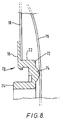
- Figs. 5-8 illustrate a modified form of bagside coupling member 70. This is similar to the bagside coupling member 14 of the first embodiment, except for the following features:
- the projections 74 act as an anti-sealing means to reduce any tendency for the plastics coupling member to stick to the rear wall 76 of the pouch. Such sticking is similar to the well-known problem of pouch pancaking, and might otherwise obstruct the passage of faecal matter through the bagside coupling member 70 and into the pouch. It is believed that the projections 74 (and the clearances between adjacent projections 74) considerably reduce the problem of sticking.
- the projections provide a tactile indication which the user can feel by finger through the pouch wall material. This can improve the extent to which a user is able to feel by hand the profile of the coupling member through the pouch wall material, to enable the user better to position his hands during fitting of the pouch to the body. It has been appreciated that the recessed nature of the bagside flush-fit coupling member results in the coupling being considerably more hidden for the user's view, and that this loss of visibility can make the coupling more difficult to fit and to remove. Therefore, the improved tactility of the coupling through the second pouch wall compensates for the loss of visibility of the coupling member.
- any non-planar configuration of rear surface may be used to improve the tactility of the coupling through the pouch wall.
- a non-stick coating may be applied to the rear surface 72 of the coupling 70, or to the confronting pouch wall 76 to provide or enhance the non-stick effect.
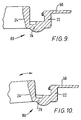
- Figs. 9 and 10 illustrate a further modified embodiment of bagside coupling member 80.
- This is very similar to the bagside coupling member 70 illustrated in Figs. 5 to 8, but in the present embodiment, the inner wall 24 tapers in thickness towards the junction with the channel floor 26. This reduced thickness provides a natural hinging effect to improve the ease with which the channel is able to open when flexed. This can address the problem of the channel tending to be stiff as a result of being supported by the flange 60 extending from the outer wall 22 around the channel mouth. Such stiffness might result in a high insertion force being required to assemble the bagside coupling member to the bodyside coupling member, and also a high peeling forced being required to separate the coupling members.
- the inner wall 24 is able to flex during assembly, and during peeling of the bagside coupling member, making the coupling easier to use without compromising the seal and security characteristics of the coupling.
- a two-piece ostomy coupling 110 consists generally of a bodyside coupling member 112 and a bagside coupling member 114.
- the bagside member 114 comprises a flange 116 which in this embodiment is attached to the outer face of a pouch wall 118 by gluing, welding, or any other suitable form of fixing.
- the flange 116 could be attached to the inner face of the wall 118 if desired.
- the flange 116 has a stomal aperture which is aligned with a corresponding aperture 120 in the pouch wall 118.
- an outer cylindrical wall 122 which extends rearwardly into the pouch, and positioned concentrically inside the outer wall 122 is a cylindrical inner wall 124.
- the inner wall 124 and the outer wall 122 define a channel 126, and are connected to each other by a channel floor 128.
- a number of radially projecting belt tabs and/or pull tabs 130 are provided as extensions of the front flange 116, to enable the flange 116 to be gripped, as described later.
- the floor 128 of the channel 126 includes a plurality of, in this embodiment, regularly spaced, recesses 132 for facilitating moulding of the coupling member in the same manner as the recesses 30 in the first embodiment.
- the inner wall 124 carries, on its outer face, a plurality of spaced apart projections 134. These serve to form an interlock with a corresponding formation of the bodyside coupling member 112.
- Each projection 134 includes a generally planar flat or undercut rear surface 136, and an upper ramp surface 138.
- the bodyside member 112 comprises an annular flange 140 which is attached to an adhesive "wafer” or pad 142 for attachment to a person's skin.
- the pad 142 may be made of Stomadhesive or other known skin adhesives; such adhesives are well known to the skilled man and so are not described further here.
- the flange 140 includes a stomal aperture 144 bounded by a generally annular formation 146 configured to fit within the channel 126 and including a first portion made of relatively hard plastics material, and a second portion made of a relatively soft plastics material.
- the first portion includes a generally cylindrical rib 148 which carries on its inner face a stepped or undercut locking formation 150 for co-operating with the projections 134.
- the second portion comprises at least one (and in this embodiment two) generally radial sealing fins 152 which project radially outwardly from the rib 148.
- Each fin 152 extends from a base support region 154, and tapers towards its tip.
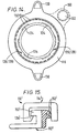
- the fins 152 are dimensioned to be slightly "oversize" for fitting within the channel 126. Therefore, as best seen in Fig. 14, when the coupling members 112 and 114 are assembled, the tips of the fins 152 will engage against, and be deflected by, the inner surface of the outer channel wall 122. The bent tip of each fin 152 therefore engages the outer channel wall 122 over an axially spread cylindrical region, to increase the overall area of the seal. Such spreading of each seal over a cylindrical band can achieve much better seal performance than some other types of prior art low-profile seal which just tend to provide point sealing characteristics. In particular, the seal achieves the following advantages:
- each fin 152 ensures that any deflection of the fin 152 will occur predominantly at the tip, to achieve the desired cylindrical seal, rather than a point seal.
- the fins 152 are dimensioned to be slightly larger than the maximum envisaged channel size, bearing in mind the manufacturing tolerances of the coupling members.
- sealing fins are illustrated, a single fin, or three or more fins may be used instead if desired. If more than one fin 152 is used, then in the present embodiment these project radially outwardly, for ease of moulding.
- the sealing fins 152 are of a different, softer material than the cylindrical rib 148.
- Convenient manufacturing techniques for producing the bodyside coupling member 112 of two materials include two shot moulding, and insert injection moulding.
- the base support region 154 provides additional contact area between the hard and soft materials to ensure that a firm integral connection is achieved during two shot moulding.
- any suitable production technique including manual assembly of separate component parts, may be used as desired.
- a suitable material for the rib 48 and the flange 140 is STD PVA Copolymer.
- a suitable material for the sealing fins 152 is synthetic rubber. Such materials can be chosen which bond chemically when two-shot moulded. If non-bonding materials are used, then a mechanical keying arrangement will need to be used.
- the sealing fins 152 and the rib 148 may be integrally moulded of the same material, for example, a flexible polymer.
- the flange 140 of the bagside coupling member 114 may carry an integral mounting 160 for a flatus filter (depicted schematically at 162).
- the mounting 160 may be in the form of an openable carrier to enable the filter 162 to be replaced, or it may be sealed closed.
- the mounting 160 is in the form of a lateral extension of the flange 140.
- the mounting 160 may take any suitable form, for example, a satellite coupled by webs to the flange 140, or be part of the flange 140.
- Such an integral filter assembly can provide additional advantages in terms of ease of manufacture, by providing self alignment of the filter. and also providing attachment of the filter and coupling member to the pouch in one welding step (rather than separate steps for the coupling member and for the filter).
- the formation 146 of the bodyside member 112 is pressed into the channel 126 of the bagside member 114. This requires only a modest insertion force.
- the locking formation 150 forms a snap fit with the projections 134 of the inner channel wall 124.
- the sealing fins 152 deflect to form a seal against the inner surface of the outer channel wall 122.
- the user grips one of the belt tabs/pull tabs 30 and peels the bagside member 114 off the body side member 112.
- the bagside coupling member 114 is sufficiently flexible to enable the two coupling members to be separated with only a modest separation force being required. However, in normal use while being worn, the interlock between the locking formation 150 and the projections 134 maintains a secure fastening between the coupling members.
- the outer channel wall 122 and the inner channel wall 124 depend rearwardly from the front flange 116 of the bagside coupling member.
- the channel 126 is therefore "recessed" into the interior of the pouch. This can provide the impression of a very low profile coupling, because the pouch fits very closely to the adhesive pad 142, and the majority of the profile height of the coupling is concealed inside the pouch. If desired, any of the modification features illustrated in Figs. 5-10 could also be included in the present embodiment.
- the inner and outer channel walls 124 and 122 could if desired project forwardly from the flange 116, such that the flange is generally co-planar with the floor 128 of the channel 126.
- the flange 140 of the bagside coupling member 114 fits against the exterior face of the pouch wall.
- the bagside coupling member could be secured to the interior face of the pouch wall (as depicted in phantom in Fig. 12). Such an alternative arrangement could also use the integral filter mounting 160.
- the "female" coupling member 114 (with the channel 126) is on the bag-side, and the “male” coupling member 112 (with the projecting formation 146) is on the body side.
- the two-shot moulded male member will be slightly more expensive to produce than the single-shot moulded female member.
- the bagside member will be replaced more frequently than the bodyside member, and so it may be advantageous to use the cheaper coupling member as the more frequently replaced member.
- the male and female members may be interchanged so that the female member is on the body side, and the male member is on the bag side.
- Fig. 15 illustrates a modified embodiment of coupling 110'. This is similar to the first embodiment described above, and the same reference numerals are used where appropriate.
- the main difference in the second embodiment is that the sealing fins 152' project radially inwardly, and the locking formation 150' is on the radially outer edge of the formation 146'.
- the coupling functions in the same manner as the first embodiment, and can achieve the same reliable seal and low profile height as the first embodiment. However, at the current time, the first embodiment is preferred for ease of moulding.
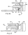
- FIG 16 illustrates a further embodiment of ostomy coupling 200, being a three piece coupling.
- the coupling consists of a bagside coupling member 202, and a bodyside coupling member 204 carrying a springy split locking ring 206.
- the function of the split locking ring is as described in GB-A-2299761 to which the reader is referred.
- the locking ring 206 carries a number of locking tabs 208 which project through apertures 210 in the coupling member 204, to engage the bagside coupling member 202 to secure the two coupling members together.
- the upper edges of the tabs 208 are tapered to enable the bagside coupling member 202 to be inserted with a snap fit.
- the ring 206 is manipulated, e.g. moved angularly, causing the tabs to become withdrawn by a cam action against the edge surfaces (not shown) of the apertures 210. Once the tabs have been withdrawn radially, the bagside coupling member 202 can be separated from the bodyside member 204.
- the bodyside coupling member 204 carries a generally radial annular sealing fin 212 similar to the fins 152 described above.
- the fin 212 is of resilient plastics and is supported by a base 214 integrally moulded in a recess of the bodyside coupling member 204.
- the fin 212 tapes towards its tip, to form a resilient seal against a surface 216 of the bodyside coupling member 202 when the coupling members are assembled.
- the sealing fin can provide the same sealing characteristics and advantages as the fins 152 described above. Although only one sealing fin 212 is illustrated, a plurality of fins 212 may be used if desired.
- Figure 17 illustrates a further embodiment of a three piece coupling 220 similar to the coupling 200 of Fig. 16.
- the sealing fin 222 is carried by the bagside coupling member 224.
- the bodyside coupling member 226 comprises an inner cylindrical wall 228 defining a channel in which the bagside coupling member 224 is received.
- the seal fin 222 bears against the inner cylindrical wall to form a resilient cylindrical band seal thereagainst. It will be appreciated that more than one seal fin 222 may be used as desired, although a single fin 222 illustrated in this embodiment for ease of moulding.
- an ostomy pouch 310 includes a front wall 312 and a rear wall 314 of plastic film, welded together around a peripheral weld seam 316.
- the rear wall 314 of the pouch includes a stoma aperture 38 in which, typically, may be generally circular.
- Mounted around the stoma aperture 318 is a bag side coupling member which is releseably attachable to a body side coupling member worn on the body.
- the bag side coupling member 320 consists generally of a first annular member 324 secured to the rear wall 314 of the pouch, a second annular member 326, and an annular sealing diaphragm 328 sandwiched between the first and second annular members 324 and 326.
- the annular members 324 and 326 may be made, for example of plastics or of card, and the diaphragm 328 can be made of any soft, resiliently flexible material, such as rubber, soft rubber or a soft flexible thermo-plastic elastomer.
- the members 324, 326 and 328 can be secured together by any suitable means such as by adhesive, or by welding (if possible), or by a mechanical fastening or interlock.
- the second annular member 326 carries a layer of adhesive 330 for allowing releasable attachment of the bag side coupling member 320 to the body side coupling member 322.
- the adhesive is preferably of a re-positionable type (also referred to as a "pealable and resealable” adhesive). Such adhesives are known to the skilled man.
- the body side coupling member 322 comprises a generally cylindrical chute 332 from which projects a generally radial flange 334.
- the flange 334 is attached to a pad, or wafer 336 of skin compatible adhesive, such as stomadhesive, produced by Bristol-Myers Squibb company.
- the flange 334 also serves to provide a seat surface 338 against which the adhesive 330 of the bag side coupling can adhere to hold the coupling members together when the bag side coupling member 320 is pressed onto the body side coupling member 322.
- the chute 332 has an outer diameter which is smaller than the inner diameter of the annular members 324 and 326, so that the chute can be received within the annular members. However, the outer diameter of the chute 332 is greater than the inside diameter of the flexible diaphragm 328, such that the diaphragm 328 engages around the chute 332 to form a seal around the chute.
- the chute 332 forces the aperture in the diaphragm 328 to expand, and also causes the flexible diaphragm material to deflect in a direction towards the stoma aperture 318 in the pouch.
- the diaphragm material is easily flexible in order to accommodate such expansion and deflection, and thus forms a "stretched" fit around the chute 332. This can provide a reliable, generally gas-tight seal around the chute, with only a very modest "insertion" force being required to insert the chute through the diaphragm 328.
- the chute 332 is able to slide out easily from the aperture in the sealing diaphragm 328, and the sealing diaphragm 328 can return to its normal, planar shape under it's own resilience.
- Fig. 20 shows a modified form bag side coupling member 320.
- the annular members 324 and 326 are formed as a single, annular member 324'.
- the flexible diaphragm 328 of resilient material is integrally moulded with the annular member 324', for example using two-shot moulding, or insert injection moulding. This can enable can intregal coupling member to be formed of two plastics materials.
- the coupling member 324' carries the adhesive layer 330 in the same manner as illustrated in Fig. 18.
- the coupling member could be intregally moulded for a single, flexible, plastics material, for example, a flexible thermoplastic elastomer.
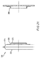
- Fig. 21 illustrates a further embodiment of ostomy coupling. This is similar to the embodiment illustrated in Fig. 20, but differs in that the sealing fin 366 is carried on the male coupling member, rather than on the female coupling member.
- the sealing fin projects generally radially from a supporting portion 372 of the same material as the fin 366.
- the supporting portion 372 is intregally moulded with the remainder of the male coupling member, by using a two-shot moulding process (or an insert injection moulding process), and the supporting portion 372 serves to provide sufficient contact area between the two materials to ensure reliable bonding during moulding.
- the flexible fin 366 has a larger outer diameter than the inner diameter of the female coupling member 380, to form a resilient seal therewith when the coupling members are assembled together.
- coupling members of the preferred embodiment are generally circular, it will be appreciated that other closed-loop shapes may be used instead if desired.
Landscapes
- Health & Medical Sciences (AREA)
- Heart & Thoracic Surgery (AREA)
- Life Sciences & Earth Sciences (AREA)
- Orthopedic Medicine & Surgery (AREA)
- Engineering & Computer Science (AREA)
- Biomedical Technology (AREA)
- Epidemiology (AREA)
- Vascular Medicine (AREA)
- Nursing (AREA)
- Animal Behavior & Ethology (AREA)
- General Health & Medical Sciences (AREA)
- Public Health (AREA)
- Veterinary Medicine (AREA)
- Orthopedics, Nursing, And Contraception (AREA)
- Materials For Medical Uses (AREA)
Claims (37)
- Raccord de stomie à ajustement à niveau, comprenant :un élément de raccord côté poche (14 ; 114) comprenant une paroi intérieure (24 ; 124) et une paroi extérieure (22 ; 122) définissant un canal entre elles, une collerette de montage (16 ; 116) s'étendant vers l'extérieur depuis la paroi extérieure au niveau d'un point distant du fond du canal, une première (22 ; 122) parmi les parois intérieure et extérieure comprenant au moins une saillie de blocage (34 ; 134) orientée vers une seconde paroi parmi les parois intérieure et extérieure, etun élément de raccord côté corps (12 ; 112) comprenant une saillie (46 ; 146) qui, en utilisation, est reçue à l'intérieur du canal de l'élément de raccord côté poche, la saillie comprenant une formation (46 ; 146) destinée à une mise en prise de blocage mutuel avec la saillie de blocage de la première paroi de l'élément de raccord côté poche, caractérisé en ce que ledit raccord comprend un joint d'étanchéité pouvant fléchir (54 ; 154) destiné à une mise en prise sans blocage mutuel avec la seconde paroi de l'élément de raccord côté poche.
- Raccord selon la revendication 1, dans lequel la collerette (16 ; 116) s'étend depuis un point adjacent à l'ouverture du canal.
- Raccord selon la revendication 1 ou 2, dans lequel l'élément côté poche comprend en outre une nervure de positionnement (28) faisant saillie depuis le fond du canal dans une moindre mesure par rapport à la première et la seconde paroi.
- Elément de raccord selon la revendication 3, dans lequel l'élément côté corps comprend une rainure (56) entre la formation de blocage et le joint d'étanchéité, la rainure étant configurée pour recevoir la nervure de positionnement (28) lorsque les éléments de raccord sont assemblés.
- Raccord selon la revendication 4, dans lequel la nervure de positionnent (28) est configurée pour ne pas être à ajustement serré à l'intérieur de la rainure.
- Raccord selon l'une quelconque des revendications précédentes, dans lequel la seconde paroi (24 ; 124) de l'élément de raccord côté poche présente une surface d'étanchéité généralement lisse orientée vers la première paroi contre laquelle le joint d'étanchéité pouvant fléchir (54 ; 154) porte lorsque les éléments de raccord sont assemblés.
- Raccord selon l'une quelconque des revendications précédentes, dans lequel la paroi intérieure (24) dépasse la paroi extérieure (22).
- Raccord de stomie à ajustement à niveau, comprenant :un élément de raccord côté poche (14) comprenant une paroi intérieure (24) et une paroi extérieure (22) définissant un canal entre elles, une collerette de montage (16) s'étendant vers l'extérieur depuis la paroi extérieure au niveau d'un point distant du fond du canal, etun élément de raccord côté corps (12) comprenant une saillie (46) qui, en utilisation, est reçue à l'intérieur du canal de l'élément de raccord côté poche en vue d'une mise en prise de blocage mutuel avec celui-ci, caractérisé en ce que l'élément de raccord côté poche comprend une paroi intérieure (24) dépassant de la paroi extérieure.
- Raccord selon la revendication 8, dans lequel la collerette (16) s'étend depuis un point adjacent à l'ouverture du canal.
- Raccord selon la revendication 8 ou 9, dans lequel la paroi intérieure (24) dépasse de la collerette (16).
- Raccord selon l'une quelconque des revendications précédentes, dans lequel le canal comprend une partie de paroi (24) d'épaisseur réduite pour réaliser un point d'articulation naturel.
- Raccord de stomie à ajustement à niveau, comprenant :un élément de raccord côté poche (14) comprenant une paroi intérieure (24) et une paroi extérieure (22) définissant un canal entre elles, une collerette de montage (16) s'étendant vers l'extérieur depuis la paroi extérieure au niveau d'un point distant du fond du canal (26), etun élément de raccord côté corps (12) comprenant une saillie (46) qui, en utilisation, est reçue à l'intérieur du canal de l'élément de raccord côté poche en vue d'une mise en prise de blocage mutuel avec celui-ci, caractérisé en ce qu'au moins une partie de la paroi intérieure (24) ou de la paroi extérieure (22) ou du fond du canal (26) comprend une partie (24) d'épaisseur réduite pour réaliser un point d'articulation naturel pour permettre un élargissement temporaire du canal.
- Raccord selon la revendication 11 ou 12, dans lequel la partie d'épaisseur réduite (24) comprend une partie amincie.
- Raccord selon la revendication 11, 12 ou 13, dans lequel la paroi intérieure (24) comprend la partie d'épaisseur réduite.
- Raccord selon l'une quelconque des revendications précédentes, dans lequel l'élément côté poche comprend un moyen anti-adhérence (74) sur l'arrière du fond du canal.
- Raccord selon la revendication 15, dans lequel le moyen anti-adhérence (74) comprend un revêtement de matériau anti-adhérence.
- Raccord selon la revendication 15, dans lequel le moyen anti-adhérence comprend une région non plane (74).
- Raccord selon l'une quelconque des revendications 1 à 14, dans lequel la surface arrière du fond du canal est sensiblement non plane.
- Elément de raccord côté poche (14 ; 114) d'un raccord de stomie à ajustement à niveau, destiné à un raccordement à un élément de raccord côté corps, l'élément de raccord côté poche comprenant :caractérisé en ce que, parmi les parois intérieure et extérieure seule une première (22 ; 122) des parois intérieure et extérieure comprend une saillie de blocage (34 ; 134) orientée vers l'intérieur du canal, une seconde (24 ; 124) des parois intérieure et extérieure comprenant une surface d'étanchéité généralement lisse.des parois intérieure et extérieure généralement concentriques (22, 24 ; 122, 124) définissant un canal entre elles,une collerette de fixation (16 ; 116) s'étendant généralement radialement vers l'extérieur depuis un point distant du fond du canal,
- Elément de raccord selon la revendication 19, dans lequel la collerette (16 ; 116) s'étend depuis un point adjacent à l'ouverture du canal.
- Elément de raccord selon la revendication 19 ou 20, dans lequel la première paroi (22 ; 122) porte une pluralité de saillies de blocage espacées.
- Elément de raccord selon la revendication 19, 20 ou 21, dans lequel la paroi intérieure (24 ; 124) dépasse la paroi extérieure (22 ; 122).
- Elément de raccord côté poche (14) destiné à un raccord de stomie à ajustement à niveau, destiné à un raccordement à un élément de raccord côté corps, l'élément de raccord côté poche comprenant :caractérisé en ce que la paroi intérieure (24) dépasse la paroi extérieure (22).des parois intérieure et extérieure généralement concentriques (22, 24) définissant un canal entre elles,une collerette de fixation (16) s'étendant généralement radialement vers l'extérieur depuis un point distant du fond du canal,
- Elément de raccord selon l'une quelconque des revendications 19 à 23, dans lequel le canal comprend une partie de paroi (24) d'épaisseur réduite pour réaliser un point d'articulation naturel.
- Elément de raccord côté poche (14) d'un raccord de stomie à ajustement à niveau, destiné à un raccordement à un élément de raccord côté corps, l'élément de raccord côté poche comprenant :caractérisé en ce qu'au moins une partie de la paroi intérieure (24), de la paroi extérieure (22) ou bien du fond du canal (26) comprend une partie (24) d'épaisseur réduite pour réaliser un point d'articulation naturel pour permette un élargissement temporaire du canal.des parois intérieure et extérieure généralement concentriques (22, 24) définissant un canal entre elles,une collerette de fixation (16) s'étendant généralement radialement vers l'extérieur depuis un point distant du fond du canal,
- Elément de raccord selon la revendication 24 ou 25, dans lequel la partie d'épaisseur réduite (24) comprend une partie amincie.
- Elément de raccord selon la revendication 24, 25 ou 26, dans lequel la paroi intérieure (24) comprend la partie d'épaisseur réduite.
- Elément de raccord selon l'une quelconque des revendications 19 à 27, dans lequel l'élément côté poche comprend un moyen anti-adhérence (74) sur l'arrière du fond du canal.
- Elément de raccord selon la revendication 28, dans lequel le moyen anti-adhérence (74) comprend un revêtement de matériau anti-adhérence.
- Elément de raccord selon la revendication 28, dans lequel le moyen anti-adhérence comprend une région non plane (74).
- Elément de raccord selon l'une quelconque des revendications 19 à 27, dans lequel la surface arrière du fond du canal est sensiblement non plane.
- Elément de raccord selon l'une quelconque des revendications 19 à 31, comprenant en outre un élément d'étanchéité (154) porté par une paroi de l'élément de raccord et faisant saillie radialement depuis celle-ci ou s'étendant radialement depuis celle-ci, l'élément d'étanchéité étant d'un matériau élastique qui est plus mou que le matériau de la paroi.
- Elément de raccord selon la revendication 32, dans lequel l'élément d'étanchéité (154) est d'une matière plastique.
- Elément de raccord selon la revendication 33, dans lequel l'élément d'étanchéité (154) est moulé en une seule pièce avec la paroi.
- Elément de raccord selon la revendication 32, 33 ou 34, dans lequel l'élément d'étanchéité (154) s'amincit vers son bord libre.
- Poche de stomie portant un élément de raccord tel que défini dans l'une quelconque des revendications 19 à 35.
- En combinaison, poche de stomie et raccord de stomie tels que définis dans l'une quelconque des revendications 1 à 18.
Priority Applications (2)
| Application Number | Priority Date | Filing Date | Title |
|---|---|---|---|
| JP36443699A JP4209571B2 (ja) | 1998-12-22 | 1999-12-22 | 平面嵌合造瘻カップリング、袋側カップリング部材、カップリング部材、造瘻カップリング、造瘻袋、および、造瘻袋と造瘻カップリングとの組合せ |
| AU2003248477A AU2003248477B2 (en) | 1998-12-22 | 2003-10-01 | Ostomy coupling |
Applications Claiming Priority (3)
| Application Number | Priority Date | Filing Date | Title |
|---|---|---|---|
| GB9828391 | 1998-12-22 | ||
| GB9828391A GB2344998A (en) | 1998-12-22 | 1998-12-22 | Ostomy coupling |
| US09/467,424 US6537261B1 (en) | 1998-12-22 | 1999-12-20 | Ostomy coupling |
Publications (2)
| Publication Number | Publication Date |
|---|---|
| EP1013250A1 EP1013250A1 (fr) | 2000-06-28 |
| EP1013250B1 true EP1013250B1 (fr) | 2004-02-25 |
Family
ID=26314894
Family Applications (1)
| Application Number | Title | Priority Date | Filing Date |
|---|---|---|---|
| EP99309999A Expired - Lifetime EP1013250B1 (fr) | 1998-12-22 | 1999-12-13 | Accouplement d'ostomie |
Country Status (10)
| Country | Link |
|---|---|
| US (1) | US6537261B1 (fr) |
| EP (1) | EP1013250B1 (fr) |
| AT (1) | ATE260077T1 (fr) |
| AU (1) | AU762628B2 (fr) |
| CA (1) | CA2292971C (fr) |
| DE (1) | DE69915018T2 (fr) |
| DK (1) | DK1013250T3 (fr) |
| ES (1) | ES2214819T3 (fr) |
| GB (1) | GB2344998A (fr) |
| ZA (1) | ZA997799B (fr) |
Families Citing this family (23)
| Publication number | Priority date | Publication date | Assignee | Title |
|---|---|---|---|---|
| GB2414937C (en) * | 2004-06-10 | 2017-12-06 | Welland Medical Ltd | Attachment mechanism for ostomy bags |
| GB2458662A (en) * | 2008-03-26 | 2009-09-30 | Salts Healthcare Ltd | Ostomy appliance with alignment positioning means |
| US8328779B2 (en) * | 2008-05-30 | 2012-12-11 | Marlen Manufacturing & Development, Inc. | Locating flange for a two-piece ostomy adhesive mount |
| WO2010008385A1 (fr) * | 2008-07-16 | 2010-01-21 | Bristol-Myers Squibb Company | Raccord stomique adhésif |
| AU2009316291B2 (en) * | 2008-11-19 | 2015-09-17 | Convatec Technologies Inc. | Ostomy pouch appliance |
| EP2246015A1 (fr) * | 2009-05-01 | 2010-11-03 | Hollister Incorporated | Système de couplage d'appareillage stomique et appareillage stomique |
| HUE025825T2 (en) | 2009-10-01 | 2016-05-30 | Ostomycure As | Medical closure |
| US10130506B2 (en) | 2010-03-02 | 2018-11-20 | Ostosolutions, LLC | Closure system for an ostomy pouch and related methods |
| US8690848B2 (en) * | 2010-03-02 | 2014-04-08 | Ostosolutions, LLC | Closure for ostomy pouch and method thereof |
| FR2967050B1 (fr) | 2010-11-10 | 2012-12-28 | Braun B Med Sas | Organe de connexion d'un appareillage de stomie et raccord pour appareillage de stomie |
| US8945076B2 (en) * | 2011-08-03 | 2015-02-03 | Hollister Incorporated | Ostomy appliance with integrated belt tabs |
| DK3024424T3 (da) | 2013-07-23 | 2022-10-24 | Convatec Technologies Inc | Formbare klæbeskiver |
| WO2015031574A1 (fr) * | 2013-08-30 | 2015-03-05 | Bruce Goldsmith | Systèmes et ensembles pour appareils de stomie |
| US10034793B2 (en) * | 2014-06-16 | 2018-07-31 | Sarasota Medical Products, Inc. | Coupling systems including interlocking male and female members |
| US9795501B2 (en) * | 2014-09-15 | 2017-10-24 | Achilles Nassopoulos | Ostomy appliance removable washable reusable non-adhesive sealing member |
| DK178391B1 (da) * | 2015-03-18 | 2016-10-17 | Multi-Lock Aps | Stomianordning |
| GB201806045D0 (en) * | 2018-04-12 | 2018-05-30 | Ostomycure As | Lid |
| CN109248016B (zh) * | 2018-09-27 | 2020-07-10 | 中国人民解放军陆军军医大学第三附属医院(野战外科研究所) | 一种医用造瘘袋 |
| US11590017B2 (en) * | 2019-04-25 | 2023-02-28 | Convatec Technologies Inc. | Ostomy wafers incorporating adhesives, ostomy devices including the same, and methods of applying ostomy wafers and ostomy devices |
| US11857454B2 (en) * | 2021-07-04 | 2024-01-02 | Sanguine Technology, LLC | Ostomy faceplates configured for use in close proximity with creases, rolls, or folds |
| US11129744B2 (en) * | 2019-07-08 | 2021-09-28 | Sanguine Technologies, LLC | Systems and methods for providing ostomy faceplates in close proximity with negative pressure wound devices |
| GB2591281B (en) * | 2020-01-24 | 2024-05-08 | Salts Healthcare Ltd | An ostomy appliance |
| US11590016B1 (en) * | 2020-01-28 | 2023-02-28 | Kayal Medical Products LLC | Ostomy system |
Family Cites Families (17)
| Publication number | Priority date | Publication date | Assignee | Title |
|---|---|---|---|---|
| GB1571657A (en) * | 1977-03-30 | 1980-07-16 | Kingsdown Medical Consultants | Ostomy bag |
| GB1586823A (en) * | 1978-01-27 | 1981-03-25 | Kingsdown Medical Consultants | Adhesive pad or dressing |
| US4872869A (en) * | 1982-06-09 | 1989-10-10 | Smith & Nephew (Latin America), Inc. | Low profile ostomy device |
| GB2183481B (en) * | 1985-12-10 | 1989-10-11 | Craig Med Prod Ltd | Ostomy appliance |
| GB2254785B (en) * | 1991-04-18 | 1994-07-13 | Squibb & Sons Inc | Ostomy coupling |
| JP3428989B2 (ja) | 1992-05-12 | 2003-07-22 | イー.アール.スクィブ アンド サンズ,インコーポレイテッド | 樹脂製品の成形方法およびこれによる製品 |
| DK170206B1 (da) * | 1993-02-22 | 1995-06-19 | Coloplast As | Stomikobling |
| CA2134148C (fr) * | 1993-10-28 | 2005-03-08 | Peter Leslie Steer | Dispositif pour les cas d'incontinence chez les hommes |
| GB9411790D0 (en) * | 1994-06-13 | 1994-08-03 | Edwards John V | An ostomy coupling |
| US5549588A (en) * | 1994-08-12 | 1996-08-27 | E. R. Squibb & Sons, Inc. | Coupling device for ostomy pouch |
| US5853403A (en) * | 1994-10-25 | 1998-12-29 | Kimberly-Clark Worldwide, Inc. | Absorbent article with body contacting liquid control member |
| GB2298794A (en) * | 1995-03-09 | 1996-09-18 | Squibb & Sons Inc | Ostomy coupling with intervening support ring |
| GB2299510B (en) * | 1995-04-06 | 1997-03-12 | Squibb & Sons Inc | Ostomy coupling |
| GB9507667D0 (en) | 1995-04-13 | 1995-05-31 | Squibb & Sons Inc | A coupling |
| GB2323285B (en) | 1997-03-21 | 1999-09-29 | Bristol Myers Squibb Co | Orifice couplings parts therefor and methods of production |
| US6093276A (en) * | 1998-06-11 | 2000-07-25 | Hollister Incorporated | In-line method of manufacture of ostomy appliance faceplate |
| US6106507A (en) * | 1998-06-11 | 2000-08-22 | Hollister Incorporated | Ostomy appliance faceplate with barrier layer, extended covering layer, and unitary protective release sheet and method of making |
-
1998
- 1998-12-22 GB GB9828391A patent/GB2344998A/en not_active Withdrawn
-
1999
- 1999-12-13 DE DE69915018T patent/DE69915018T2/de not_active Expired - Lifetime
- 1999-12-13 ES ES99309999T patent/ES2214819T3/es not_active Expired - Lifetime
- 1999-12-13 DK DK99309999T patent/DK1013250T3/da active
- 1999-12-13 AT AT99309999T patent/ATE260077T1/de not_active IP Right Cessation
- 1999-12-13 EP EP99309999A patent/EP1013250B1/fr not_active Expired - Lifetime
- 1999-12-20 US US09/467,424 patent/US6537261B1/en not_active Expired - Fee Related
- 1999-12-21 ZA ZA9907799A patent/ZA997799B/xx unknown
- 1999-12-21 CA CA002292971A patent/CA2292971C/fr not_active Expired - Fee Related
- 1999-12-22 AU AU65417/99A patent/AU762628B2/en not_active Ceased
Also Published As
| Publication number | Publication date |
|---|---|
| ES2214819T3 (es) | 2004-09-16 |
| GB2344998A (en) | 2000-06-28 |
| DE69915018D1 (de) | 2004-04-01 |
| EP1013250A1 (fr) | 2000-06-28 |
| DK1013250T3 (da) | 2004-06-21 |
| ZA997799B (en) | 2001-06-21 |
| AU762628B2 (en) | 2003-07-03 |
| US6537261B1 (en) | 2003-03-25 |
| ATE260077T1 (de) | 2004-03-15 |
| CA2292971A1 (fr) | 2000-06-22 |
| AU6541799A (en) | 2000-06-29 |
| CA2292971C (fr) | 2008-06-03 |
| DE69915018T2 (de) | 2004-11-25 |
| GB9828391D0 (en) | 1999-02-17 |
Similar Documents
| Publication | Publication Date | Title |
|---|---|---|
| EP1013250B1 (fr) | Accouplement d'ostomie | |
| US5647861A (en) | Ostomy coupling | |
| JP3621399B2 (ja) | 連結部材およびカップリング | |
| JP3853425B2 (ja) | カップリング | |
| GB2333963A (en) | Orifice couplings, parts therefor and methods of production | |
| JPH03168146A (ja) | 人工肛門用カップリング | |
| JPH0528146B2 (fr) | ||
| JPH0626554B2 (ja) | 人工肛門用具 | |
| US5957905A (en) | Orifice coupling | |
| JPH0444548B2 (fr) | ||
| JP4209571B2 (ja) | 平面嵌合造瘻カップリング、袋側カップリング部材、カップリング部材、造瘻カップリング、造瘻袋、および、造瘻袋と造瘻カップリングとの組合せ | |
| JPH0528145B2 (fr) | ||
| AU2003248477B2 (en) | Ostomy coupling | |
| US5178615A (en) | Ostomy bag coupling | |
| NZ501999A (en) | Easy working couplings with seals for ostomy bags | |
| EP0988843A1 (fr) | Accouplement d'ostomie | |
| MXPA00000121A (en) | Ostomy coupling | |
| GB2219507A (en) | An ostomy bag coupling | |
| EP0830855B1 (fr) | Accouplement stomique | |
| AU684121B2 (en) | Ostomy coupling | |
| GB2323286A (en) | Orifice coupling | |
| MXPA99007913A (en) | Coupling of osto | |
| MXPA98000516A (en) | Coupling of orifi |
Legal Events
| Date | Code | Title | Description |
|---|---|---|---|
| PUAI | Public reference made under article 153(3) epc to a published international application that has entered the european phase |
Free format text: ORIGINAL CODE: 0009012 |
|
| AK | Designated contracting states |
Kind code of ref document: A1 Designated state(s): AT BE CH CY DE DK ES FI FR GB GR IE IT LI LU MC NL PT SE |
|
| AX | Request for extension of the european patent |
Free format text: AL;LT;LV;MK;RO;SI |
|
| 17P | Request for examination filed |
Effective date: 20001108 |
|
| AKX | Designation fees paid |
Free format text: AT BE CH CY DE DK ES FI FR GB GR IE IT LI LU MC NL PT SE |
|
| 17Q | First examination report despatched |
Effective date: 20030213 |
|
| GRAP | Despatch of communication of intention to grant a patent |
Free format text: ORIGINAL CODE: EPIDOSNIGR1 |
|
| GRAS | Grant fee paid |
Free format text: ORIGINAL CODE: EPIDOSNIGR3 |
|
| GRAA | (expected) grant |
Free format text: ORIGINAL CODE: 0009210 |
|
| AK | Designated contracting states |
Kind code of ref document: B1 Designated state(s): AT BE CH CY DE DK ES FI FR GB GR IE IT LI LU MC NL PT SE |
|
| PG25 | Lapsed in a contracting state [announced via postgrant information from national office to epo] |
Ref country code: NL Free format text: LAPSE BECAUSE OF FAILURE TO SUBMIT A TRANSLATION OF THE DESCRIPTION OR TO PAY THE FEE WITHIN THE PRESCRIBED TIME-LIMIT Effective date: 20040225 Ref country code: LI Free format text: LAPSE BECAUSE OF FAILURE TO SUBMIT A TRANSLATION OF THE DESCRIPTION OR TO PAY THE FEE WITHIN THE PRESCRIBED TIME-LIMIT Effective date: 20040225 Ref country code: FI Free format text: LAPSE BECAUSE OF FAILURE TO SUBMIT A TRANSLATION OF THE DESCRIPTION OR TO PAY THE FEE WITHIN THE PRESCRIBED TIME-LIMIT Effective date: 20040225 Ref country code: CY Free format text: LAPSE BECAUSE OF FAILURE TO SUBMIT A TRANSLATION OF THE DESCRIPTION OR TO PAY THE FEE WITHIN THE PRESCRIBED TIME-LIMIT Effective date: 20040225 Ref country code: CH Free format text: LAPSE BECAUSE OF FAILURE TO SUBMIT A TRANSLATION OF THE DESCRIPTION OR TO PAY THE FEE WITHIN THE PRESCRIBED TIME-LIMIT Effective date: 20040225 Ref country code: BE Free format text: LAPSE BECAUSE OF FAILURE TO SUBMIT A TRANSLATION OF THE DESCRIPTION OR TO PAY THE FEE WITHIN THE PRESCRIBED TIME-LIMIT Effective date: 20040225 Ref country code: AT Free format text: LAPSE BECAUSE OF FAILURE TO SUBMIT A TRANSLATION OF THE DESCRIPTION OR TO PAY THE FEE WITHIN THE PRESCRIBED TIME-LIMIT Effective date: 20040225 |
|
| REG | Reference to a national code |
Ref country code: GB Ref legal event code: FG4D |
|
| REG | Reference to a national code |
Ref country code: CH Ref legal event code: EP |
|
| REG | Reference to a national code |
Ref country code: IE Ref legal event code: FG4D |
|
| REF | Corresponds to: |
Ref document number: 69915018 Country of ref document: DE Date of ref document: 20040401 Kind code of ref document: P |
|
| PG25 | Lapsed in a contracting state [announced via postgrant information from national office to epo] |
Ref country code: SE Free format text: LAPSE BECAUSE OF FAILURE TO SUBMIT A TRANSLATION OF THE DESCRIPTION OR TO PAY THE FEE WITHIN THE PRESCRIBED TIME-LIMIT Effective date: 20040525 Ref country code: GR Free format text: LAPSE BECAUSE OF FAILURE TO SUBMIT A TRANSLATION OF THE DESCRIPTION OR TO PAY THE FEE WITHIN THE PRESCRIBED TIME-LIMIT Effective date: 20040525 |
|
| REG | Reference to a national code |
Ref country code: DK Ref legal event code: T3 |
|
| NLV1 | Nl: lapsed or annulled due to failure to fulfill the requirements of art. 29p and 29m of the patents act | ||
| REG | Reference to a national code |
Ref country code: CH Ref legal event code: PL |
|
| REG | Reference to a national code |
Ref country code: ES Ref legal event code: FG2A Ref document number: 2214819 Country of ref document: ES Kind code of ref document: T3 |
|
| ET | Fr: translation filed | ||
| PLBQ | Unpublished change to opponent data |
Free format text: ORIGINAL CODE: EPIDOS OPPO |
|
| PLBI | Opposition filed |
Free format text: ORIGINAL CODE: 0009260 |
|
| PG25 | Lapsed in a contracting state [announced via postgrant information from national office to epo] |
Ref country code: LU Free format text: LAPSE BECAUSE OF NON-PAYMENT OF DUE FEES Effective date: 20041213 Ref country code: IE Free format text: LAPSE BECAUSE OF NON-PAYMENT OF DUE FEES Effective date: 20041213 |
|
| PG25 | Lapsed in a contracting state [announced via postgrant information from national office to epo] |
Ref country code: MC Free format text: LAPSE BECAUSE OF NON-PAYMENT OF DUE FEES Effective date: 20041231 |
|
| PLAX | Notice of opposition and request to file observation + time limit sent |
Free format text: ORIGINAL CODE: EPIDOSNOBS2 |
|
| 26 | Opposition filed |
Opponent name: COLOPLAST A/S Effective date: 20041116 |
|
| PLAX | Notice of opposition and request to file observation + time limit sent |
Free format text: ORIGINAL CODE: EPIDOSNOBS2 |
|
| PLBB | Reply of patent proprietor to notice(s) of opposition received |
Free format text: ORIGINAL CODE: EPIDOSNOBS3 |
|
| REG | Reference to a national code |
Ref country code: IE Ref legal event code: MM4A |
|
| PLCK | Communication despatched that opposition was rejected |
Free format text: ORIGINAL CODE: EPIDOSNREJ1 |
|
| PG25 | Lapsed in a contracting state [announced via postgrant information from national office to epo] |
Ref country code: PT Free format text: LAPSE BECAUSE OF NON-PAYMENT OF DUE FEES Effective date: 20040725 |
|
| PLBN | Opposition rejected |
Free format text: ORIGINAL CODE: 0009273 |
|
| STAA | Information on the status of an ep patent application or granted ep patent |
Free format text: STATUS: OPPOSITION REJECTED |
|
| 27O | Opposition rejected |
Effective date: 20071130 |
|
| REG | Reference to a national code |
Ref country code: GB Ref legal event code: 732E |
|
| REG | Reference to a national code |
Ref country code: FR Ref legal event code: TP |
|
| PGFP | Annual fee paid to national office [announced via postgrant information from national office to epo] |
Ref country code: IT Payment date: 20101218 Year of fee payment: 12 Ref country code: GB Payment date: 20101208 Year of fee payment: 12 |
|
| PGFP | Annual fee paid to national office [announced via postgrant information from national office to epo] |
Ref country code: FR Payment date: 20111219 Year of fee payment: 13 |
|
| PGFP | Annual fee paid to national office [announced via postgrant information from national office to epo] |
Ref country code: DK Payment date: 20121211 Year of fee payment: 14 |
|
| PGFP | Annual fee paid to national office [announced via postgrant information from national office to epo] |
Ref country code: DE Payment date: 20121205 Year of fee payment: 14 |
|
| PGFP | Annual fee paid to national office [announced via postgrant information from national office to epo] |
Ref country code: ES Payment date: 20121227 Year of fee payment: 14 |
|
| GBPC | Gb: european patent ceased through non-payment of renewal fee |
Effective date: 20121213 |
|
| REG | Reference to a national code |
Ref country code: FR Ref legal event code: ST Effective date: 20130830 |
|
| PG25 | Lapsed in a contracting state [announced via postgrant information from national office to epo] |
Ref country code: FR Free format text: LAPSE BECAUSE OF NON-PAYMENT OF DUE FEES Effective date: 20130102 Ref country code: GB Free format text: LAPSE BECAUSE OF NON-PAYMENT OF DUE FEES Effective date: 20121213 |
|
| PG25 | Lapsed in a contracting state [announced via postgrant information from national office to epo] |
Ref country code: IT Free format text: LAPSE BECAUSE OF NON-PAYMENT OF DUE FEES Effective date: 20121213 |
|
| REG | Reference to a national code |
Ref country code: DE Ref legal event code: R119 Ref document number: 69915018 Country of ref document: DE |
|
| REG | Reference to a national code |
Ref country code: DK Ref legal event code: EBP Effective date: 20131231 |
|
| REG | Reference to a national code |
Ref country code: DE Ref legal event code: R119 Ref document number: 69915018 Country of ref document: DE Effective date: 20140701 |
|
| PG25 | Lapsed in a contracting state [announced via postgrant information from national office to epo] |
Ref country code: DE Free format text: LAPSE BECAUSE OF NON-PAYMENT OF DUE FEES Effective date: 20140701 |
|
| PG25 | Lapsed in a contracting state [announced via postgrant information from national office to epo] |
Ref country code: DK Free format text: LAPSE BECAUSE OF NON-PAYMENT OF DUE FEES Effective date: 20131231 |
|
| REG | Reference to a national code |
Ref country code: ES Ref legal event code: FD2A Effective date: 20150504 |
|
| PG25 | Lapsed in a contracting state [announced via postgrant information from national office to epo] |
Ref country code: ES Free format text: LAPSE BECAUSE OF NON-PAYMENT OF DUE FEES Effective date: 20131214 |