EP1013301A1 - Katheter - Google Patents
Katheter Download PDFInfo
- Publication number
- EP1013301A1 EP1013301A1 EP99310476A EP99310476A EP1013301A1 EP 1013301 A1 EP1013301 A1 EP 1013301A1 EP 99310476 A EP99310476 A EP 99310476A EP 99310476 A EP99310476 A EP 99310476A EP 1013301 A1 EP1013301 A1 EP 1013301A1
- Authority
- EP
- European Patent Office
- Prior art keywords
- catheter
- end portion
- shaping member
- guide wire
- main body
- Prior art date
- Legal status (The legal status is an assumption and is not a legal conclusion. Google has not performed a legal analysis and makes no representation as to the accuracy of the status listed.)
- Granted
Links
- 238000007493 shaping process Methods 0.000 claims abstract description 27
- 238000004804 winding Methods 0.000 claims abstract description 20
- 229910045601 alloy Inorganic materials 0.000 claims description 19
- 239000000956 alloy Substances 0.000 claims description 19
- 230000000717 retained effect Effects 0.000 claims description 10
- 239000013013 elastic material Substances 0.000 claims description 7
- 229910052742 iron Inorganic materials 0.000 claims description 6
- KHYBPSFKEHXSLX-UHFFFAOYSA-N iminotitanium Chemical compound [Ti]=N KHYBPSFKEHXSLX-UHFFFAOYSA-N 0.000 claims description 4
- 229910001000 nickel titanium Inorganic materials 0.000 claims description 4
- 229910052802 copper Inorganic materials 0.000 claims description 3
- 229910052720 vanadium Inorganic materials 0.000 claims description 3
- 239000007788 liquid Substances 0.000 description 40
- 239000003814 drug Substances 0.000 description 39
- 229940079593 drug Drugs 0.000 description 39
- 210000004204 blood vessel Anatomy 0.000 description 27
- 239000000463 material Substances 0.000 description 14
- 230000003327 cancerostatic effect Effects 0.000 description 7
- 238000002347 injection Methods 0.000 description 7
- 239000007924 injection Substances 0.000 description 7
- 210000001835 viscera Anatomy 0.000 description 7
- 206010028980 Neoplasm Diseases 0.000 description 6
- 201000011510 cancer Diseases 0.000 description 6
- 230000014759 maintenance of location Effects 0.000 description 6
- 239000000126 substance Substances 0.000 description 6
- 230000000694 effects Effects 0.000 description 5
- 238000003780 insertion Methods 0.000 description 5
- 230000037431 insertion Effects 0.000 description 5
- 229910052751 metal Inorganic materials 0.000 description 4
- 239000002184 metal Substances 0.000 description 4
- 230000002093 peripheral effect Effects 0.000 description 4
- 230000000903 blocking effect Effects 0.000 description 3
- 230000017531 blood circulation Effects 0.000 description 3
- 230000036760 body temperature Effects 0.000 description 2
- 238000007796 conventional method Methods 0.000 description 2
- 239000007769 metal material Substances 0.000 description 2
- 150000002739 metals Chemical class 0.000 description 2
- 238000000034 method Methods 0.000 description 2
- 230000035515 penetration Effects 0.000 description 2
- BASFCYQUMIYNBI-UHFFFAOYSA-N platinum Chemical compound [Pt] BASFCYQUMIYNBI-UHFFFAOYSA-N 0.000 description 2
- -1 polyethylene Polymers 0.000 description 2
- 229910001285 shape-memory alloy Inorganic materials 0.000 description 2
- 229920003002 synthetic resin Polymers 0.000 description 2
- 239000000057 synthetic resin Substances 0.000 description 2
- JOYRKODLDBILNP-UHFFFAOYSA-N Ethyl urethane Chemical compound CCOC(N)=O JOYRKODLDBILNP-UHFFFAOYSA-N 0.000 description 1
- 241001465754 Metazoa Species 0.000 description 1
- 239000004677 Nylon Substances 0.000 description 1
- 239000004698 Polyethylene Substances 0.000 description 1
- 239000004743 Polypropylene Substances 0.000 description 1
- BQCADISMDOOEFD-UHFFFAOYSA-N Silver Chemical compound [Ag] BQCADISMDOOEFD-UHFFFAOYSA-N 0.000 description 1
- 238000005452 bending Methods 0.000 description 1
- 229910052797 bismuth Inorganic materials 0.000 description 1
- JCXGWMGPZLAOME-UHFFFAOYSA-N bismuth atom Chemical compound [Bi] JCXGWMGPZLAOME-UHFFFAOYSA-N 0.000 description 1
- 239000008280 blood Substances 0.000 description 1
- 210000004369 blood Anatomy 0.000 description 1
- PCHJSUWPFVWCPO-UHFFFAOYSA-N gold Chemical compound [Au] PCHJSUWPFVWCPO-UHFFFAOYSA-N 0.000 description 1
- 229910052737 gold Inorganic materials 0.000 description 1
- 239000010931 gold Substances 0.000 description 1
- 230000003446 memory effect Effects 0.000 description 1
- 229920001778 nylon Polymers 0.000 description 1
- 229910052697 platinum Inorganic materials 0.000 description 1
- 229920000573 polyethylene Polymers 0.000 description 1
- 229920001155 polypropylene Polymers 0.000 description 1
- 229920001296 polysiloxane Polymers 0.000 description 1
- 229920005989 resin Polymers 0.000 description 1
- 239000011347 resin Substances 0.000 description 1
- 238000007789 sealing Methods 0.000 description 1
- 229910052709 silver Inorganic materials 0.000 description 1
- 239000004332 silver Substances 0.000 description 1
- 239000010935 stainless steel Substances 0.000 description 1
- 229910001220 stainless steel Inorganic materials 0.000 description 1
- WFKWXMTUELFFGS-UHFFFAOYSA-N tungsten Chemical compound [W] WFKWXMTUELFFGS-UHFFFAOYSA-N 0.000 description 1
- 229910052721 tungsten Inorganic materials 0.000 description 1
- 239000010937 tungsten Substances 0.000 description 1
- 238000003466 welding Methods 0.000 description 1
Images



Classifications
-
- A—HUMAN NECESSITIES
- A61—MEDICAL OR VETERINARY SCIENCE; HYGIENE
- A61M—DEVICES FOR INTRODUCING MEDIA INTO, OR ONTO, THE BODY; DEVICES FOR TRANSDUCING BODY MEDIA OR FOR TAKING MEDIA FROM THE BODY; DEVICES FOR PRODUCING OR ENDING SLEEP OR STUPOR
- A61M25/00—Catheters; Hollow probes
- A61M25/01—Introducing, guiding, advancing, emplacing or holding catheters
- A61M25/0102—Insertion or introduction using an inner stiffening member, e.g. stylet or push-rod
-
- A—HUMAN NECESSITIES
- A61—MEDICAL OR VETERINARY SCIENCE; HYGIENE
- A61M—DEVICES FOR INTRODUCING MEDIA INTO, OR ONTO, THE BODY; DEVICES FOR TRANSDUCING BODY MEDIA OR FOR TAKING MEDIA FROM THE BODY; DEVICES FOR PRODUCING OR ENDING SLEEP OR STUPOR
- A61M25/00—Catheters; Hollow probes
- A61M25/0021—Catheters; Hollow probes characterised by the form of the tubing
- A61M25/0041—Catheters; Hollow probes characterised by the form of the tubing pre-formed, e.g. specially adapted to fit with the anatomy of body channels
-
- A—HUMAN NECESSITIES
- A61—MEDICAL OR VETERINARY SCIENCE; HYGIENE
- A61M—DEVICES FOR INTRODUCING MEDIA INTO, OR ONTO, THE BODY; DEVICES FOR TRANSDUCING BODY MEDIA OR FOR TAKING MEDIA FROM THE BODY; DEVICES FOR PRODUCING OR ENDING SLEEP OR STUPOR
- A61M25/00—Catheters; Hollow probes
- A61M25/0067—Catheters; Hollow probes characterised by the distal end, e.g. tips
- A61M25/0074—Dynamic characteristics of the catheter tip, e.g. openable, closable, expandable or deformable
-
- A—HUMAN NECESSITIES
- A61—MEDICAL OR VETERINARY SCIENCE; HYGIENE
- A61M—DEVICES FOR INTRODUCING MEDIA INTO, OR ONTO, THE BODY; DEVICES FOR TRANSDUCING BODY MEDIA OR FOR TAKING MEDIA FROM THE BODY; DEVICES FOR PRODUCING OR ENDING SLEEP OR STUPOR
- A61M25/00—Catheters; Hollow probes
- A61M25/01—Introducing, guiding, advancing, emplacing or holding catheters
- A61M25/02—Holding devices, e.g. on the body
- A61M25/04—Holding devices, e.g. on the body in the body, e.g. expansible
-
- A—HUMAN NECESSITIES
- A61—MEDICAL OR VETERINARY SCIENCE; HYGIENE
- A61M—DEVICES FOR INTRODUCING MEDIA INTO, OR ONTO, THE BODY; DEVICES FOR TRANSDUCING BODY MEDIA OR FOR TAKING MEDIA FROM THE BODY; DEVICES FOR PRODUCING OR ENDING SLEEP OR STUPOR
- A61M25/00—Catheters; Hollow probes
- A61M25/0043—Catheters; Hollow probes characterised by structural features
- A61M2025/0057—Catheters delivering medicament other than through a conventional lumen, e.g. porous walls or hydrogel coatings
-
- A—HUMAN NECESSITIES
- A61—MEDICAL OR VETERINARY SCIENCE; HYGIENE
- A61M—DEVICES FOR INTRODUCING MEDIA INTO, OR ONTO, THE BODY; DEVICES FOR TRANSDUCING BODY MEDIA OR FOR TAKING MEDIA FROM THE BODY; DEVICES FOR PRODUCING OR ENDING SLEEP OR STUPOR
- A61M25/00—Catheters; Hollow probes
- A61M25/0067—Catheters; Hollow probes characterised by the distal end, e.g. tips
- A61M25/0068—Static characteristics of the catheter tip, e.g. shape, atraumatic tip, curved tip or tip structure
-
- A—HUMAN NECESSITIES
- A61—MEDICAL OR VETERINARY SCIENCE; HYGIENE
- A61M—DEVICES FOR INTRODUCING MEDIA INTO, OR ONTO, THE BODY; DEVICES FOR TRANSDUCING BODY MEDIA OR FOR TAKING MEDIA FROM THE BODY; DEVICES FOR PRODUCING OR ENDING SLEEP OR STUPOR
- A61M25/00—Catheters; Hollow probes
- A61M25/0067—Catheters; Hollow probes characterised by the distal end, e.g. tips
- A61M25/0068—Static characteristics of the catheter tip, e.g. shape, atraumatic tip, curved tip or tip structure
- A61M25/0069—Tip not integral with tube
Definitions
- the present invention relates to a catheter, and more specifically, a catheter which can be continuously or temporarily retained inside a blood vessel or the like of a patient so that medication liquid such as carcinostatic substance can be injected in an appropriate manner.
- the medication liquid such as carcinostatic substance
- the medication liquid is generally injected to a blood vessel of the patient's body by using a syringe or an instillator.
- the medication liquid affects not only cancer cells but also normal cells because the liquid is circulated throughout the body through the blood vessels.
- the base portion side of the catheter is fixed on the patient's body so that the front end of the catheter should not move from the determined inlet position during the injection of the medication liquid.
- the front end portion of the catheter could move from the determined position during the injection due to, for example, movement of patient's body during sleep, resulting in flow of the medication liquid to some internal organs other than the targeted one.
- Japanese Patent Application Laid-Open Publication No. 10-272187 proposes a catheter in which a wire material having elasticity and a curved shape is provided at the front end inner peripheral portion of the tube-shaped catheter main body so that the front end portion of the catheter main body has a curved shape and this curve-shaped front end portion of the catheter is pressingly fixed on the wall of the blood vessel.
- a guide wire is inserted at first and its front end is disposed at the targeted position; a parent catheter is inserted along the outer periphery of the guide wire; the guide wire is pulled out when the front end of the parent catheter reaches the targeted position; and the catheter for dosing the medication liquid is inserted through the parent catheter.
- the present invention has been achieved to solve the aforementioned problems observed in use of the conventional catheter.
- the object of the present invention is to provide a catheter which can be continuously or temporarily retained in a blood vessel or the like of a patient's body and which requires only a quick and simple operation for insertion and a relatively small insertion portion.
- the catheter of the present invention includes a tube-shaped catheter main body, a shaping member which is provided at least at the front end portion of the catheter main body for imparting a winding shape to the front end portion of the catheter, and a cavity portion formed at the inner side of the shaping member.
- a guide wire can be very easily inserted through the cavity portion of the catheter. Specifically, the guide wire is at first inserted into a blood vessel or the like of a subject (e.g. a human body) and the front end portion of the guide wire is disposed at the targeted site. The catheter is then inserted along the outer periphery of the guide wire. Accordingly, the catheter can reliably be disposed at the targeted position.
- a subject e.g. a human body
- the guide wire When the catheter is disposed at the targeted site, or more specifically, when the front end portion of the catheter has reached the front end portion of the guide wire, the guide wire is pulled out so that the front end portion of the catheter restores its winding shape.
- the catheter can be then retained, in such a state, continuously or temporarily in the patient's body, so that the medication liquid is reliably dosed to the targeted portion of the subject (the patient's body) through the catheter retained in such a manner.
- the catheter to be retained in the patient's body can be inserted directly into the patient's body (the subject) without using a parent catheter.
- a parent catheter the catheter to be retained in the patient's body
- the winding front end portion of the catheter preferably has a spiral structure, so that the front end portion of the catheter can be reliably pressed and fixed on the inner periphery of the blood vessel or the like of the subject.
- the shaping member is formed preferably of a super elastic material so that the shaping member easily takes on a linear shape when the guide wire is inserted and reliably restores the winding shape when the guide wire is pulled out.
- the shaping member is preferably constructed as a coil, so that the cavity portion is reliably secured and thus the guide wire can inserted smoothly.
- the coil preferably has a flat portion on the cavity portion side, so that the cavity portion is more reliably secured and thus the guide wire can inserted more smoothly.
- the shaping member preferably has a double-helical structure when the shaping member imparts a winding shape to the front end portion of the catheter main body, so that the cavity portion is reliably secured and the winding shape reliably takes on a spiral shape.
- the shaping member may be structured as a mesh tube.
- the peripheral wall of the portion to which a winding shape is imparted by the shaping member is preferably provided with holes so that the medication liquid flows out through the holes.
- the winding shape is a spiral shape and the holes are formed at the inner side of the spiral shape so that the medication liquid is not directly injected onto the blood vessel or the like of the subject.
- the winding shape when the catheter is inserted into the subject, at the site of the subject where the catheter is retained, the winding shape preferably has a diameter which is larger than the diameter of the retention site of the subject, so that the front end portion is reliably retained at the retention site.
- Fig. 1 is a side view of a catheter according to an embodiment of the present invention in which the front end portion of the catheter is shown as a partly sectional view.
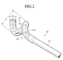
- Fig. 2 is a perspective view of the front end portion of the catheter according to the embodiment, in which view the inside of the front end portion is illustrated by phantom lines.
- Fig. 3 is a side view of the catheter according to the embodiment in which the front end portion of the catheter is shown as a partly sectional view.
- Fig. 4A is a view showing a state in which a guide wire has been inserted through the front end portion during a use of the catheter according to the embodiment
- Fig. 4B is a view showing a state in which the guide wire which has been inserted through the front end portion is being gradually pulled out during a use of the catheter according to the embodiment
- Fig. 4C is a view showing a state in which the guide wire which was inserted through the front end portion has been completely pulled out during a use of the catheter according to the embodiment.
- Fig. 5 is a view showing a state in which the catheter is being inserted into a blood vessel when the catheter is used according to the embodiment.
- Fig. 6 is a view showing a state in which the catheter is about to be connected to a medication liquid injection port when the catheter is used according to the embodiment.
- Fig. 7 is a view showing a state in which the catheter is retained in a patient's body during a use of the catheter according to the embodiment.
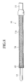
- Fig. 8 is a side view corresponding to Fig. 3 and showing another example of a shaping member of the present invention.
- a catheter 10 has a tube-shaped catheter main body 11 which is made of a synthetic resin such as urethane, nylon, polyethylene, polypropylene, silicone or a shape memory alloy or the like.
- a plug body 13 is provided at the base end portion of the catheter main body 11 such that the plug body 13 is inserted along a guide wire 12 with sealing the guide wire 12.
- the inner periphery and/or the outer periphery of the catheter main body 11 is preferably coated with a hydrophilic resin, so that the guide wire 12 can be slid against the catheter main body 11 more smoothly and/or the catheter main body 11 can be slid against the inner wall of a blood vessel or the like more smoothly.
- a tube 11a made of a material which is more flexible than the catheter main body 11 is connected to the front end portion of the catheter main body 11.
- the base end of the tube 11a is inserted into the inner periphery of the front end portion of the main body 11 and connected thereto by adhesion or welding.
- the tube 11a substantially forms the front end portion of the catheter main body 11.
- the catheter main body 11 as a whole may be formed of the same material as the tube 11a.
- a coil 14 of flat wire made from a super elastic material which will be described later is provided at the inner periphery of the tube 11a.
- the coil 14 has what is called a double helical structure in which the flat wire forms a helix (the primary helix) and the primary helix then spirals to form a larger helix (the secondary helix).
- the tube 11a portion of the catheter main body 11 is imparted a spiral shape by the double helical coil 14.
- the guide wire 12 can very easily be inserted through the catheter main body 11, as shown in Fig. 1 and Figs. 4A to 4C.
- the coil 14 serves as a shaping member in the present embodiment.
- the coil 14 is formed of a super elastic material which has been processed so that the material has a shape-memory property and super elasticity in a range of temperature near to the human body temperature. If possible, however, the coil 14 may be formed of other materials such as a metal wire (stainless steel and the like) and a FRP wire material having a high rigidity.
- Ni-Ti alloy etc. is known to show a shape memory effect and a super elasticity (pseudoelasticity) effect as a shape memory alloy.
- a super elasticity (pseudoelasticity) effect ever if a distortion load which exceeds the yield point of the alloy is applied to the alloy, the alloy restores its original shape without showing permanent deformation when the load is removed, showing excellent restoration properties against twisting and bending as well.
- the alloy of this type is distinctively different in that feature from ordinary metal materials which are permanently deformed when a distortion load which exceeds the yield point of the metal materials is applied thereto. Due to this, the alloys showing a super elasticity effect (pseudoelasticity) are suitable as the materials for the shaping member. It is further preferable to employ the alloys of which super elasticity (pseudoelasticity) effect has been controlled such that the effect is demonstrated at a temperature which is no higher than the human or animal body temperature.
- the wire material which forms the coil 14 may be an ordinary round wire. However, a flat wire (that is, a wire material of which section has a plate-like shape) as shown in the present embodiment is more preferably used. A wire material having a hemispheric section may also be used so that the flat surface faces the inner side of the coil 14. In a case in which the coil 14 is formed by a flat wire or a wire material which has a flat surface facing the inside of the coil 14, the inner cavity is more reliably secured along the center axis of the coil 14 and thus the guide wire 12 can be more smoothly inserted through the coil.
- the outer diameter A (the diameter of the secondary helix) of the coil 14 when no load is acting on the coil 14 is designed to be larger than the inner diameter of the retention site of the blood vessel or the like, so that the tube 11a has a coil-like winding shape having an outer diameter which is larger than the inner diameter of the retention site. Accordingly, when the front end portion of the catheter 10 is left in a state in which no external force is acting thereon, the coil 14 restores the coil-like shape so that the coil 14 is pressed on the inner wall of the retention site and the front end portion of the catheter 10 is fixed at the retention site.
- the inner diameter B of the inner cavity C along the center axis X of the coil 14 is designed to be larger than the outer diameter of the guide wire 12 so that the guide wire 12 can be put through the coil 14.
- the secondary helix of the coil 14 is made straight due to the rigidity of the guide wire 12 and maintained in such a linear state as shown in Fig. 1.
- a ring-shaped contrast chip 15 made of a closely-contacting coil is provided on the inner periphery of the front end portion of the tube 11a.
- materials for the contrast chip 15 metals which do not allow penetration of X ray such as gold, platinum, silver, bismuth, tungsten or alloys which contain such metals can be preferably used.
- At least one medication liquid flowing holes 16 are provided at a site or at a plurality of sites of the peripheral inner wall of the tube 11a.
- the medication liquid flowing hole(s) 16 is preferably located at a portion which is the inner side of the secondary helix when the tube 11a has restored the spiral shape of the secondary helix by the coil 14. In this arrangement, the medication liquid is prevented from being injected hard directly on the inner wall of the blood vessel or the like and thus the inner wall of the blood vessel or the like is less likely to be damaged.
- the reference number 51 is designated to the skin and the reference number 52 is designated to a blood vessel.
- a sheath 53 is inserted into the blood vessel 52 via the skin 51 according to the known Seldinger technique as shown in Fig. 5.
- the guide wire 12 is inserted through a plug body 54 provided at the base end of the sheath 53 so that the front end of the guide wire 12 is disposed at the targeted site in the blood vessel 52, for example, an blood flow inlet position from which blood flows to the internal organ which has a cancer.
- the catheter 10 is inserted so that the catheter 10 proceeds along the external periphery of the guide wire 12 until the front end of the catheter 10 reaches the front end of the guide wire 12.
- the front end portion of the catheter 10 has been extended so as to have a linear shape due to the rigidity of the guide wire 12 and can move in the blood vessel 52 relatively freely.
- the front end portion of the catheter 10 begins to take on the spiral shape due to the restoration force of the coil 14 and thus the outer diameter of the front end portion of the catheter 10 becomes larger than the diameter of the blood vessel 52.
- the front end portion of the catheter 10 starts to be pressed on the inner wall of the blood vessel 52.
- the coil 14 restores the double helical structure.
- the front end portion of the catheter 10 is pressingly fixed on the inner wall of the blood vessel 52 in a state the front end portion of the catheter 10 has taken on a spiral shape of the possible maximum diameter.
- the position at which the front end portion of the catheter 10 is fixed can be checked by means of the contrast chip 15. If the front end portion of the catheter 10 is not disposed at the targeted position, the guide wire 12 may be inserted again so as to turn the front end portion of the catheter 10 to the linear state, so that the fixing operation may be carried out again.
- the front end of the catheter 10 is now disposed at the targeted site in the blood vessel (the inlet portion from which the blood flows to the internal organ having a cancer, for example).
- the front end portion of the catheter 10 is reliably fixed inside the blood vessel 52 as described above, there is no possibility that the front end portion of the catheter 10 moves from the targeted site, even if the patient moves his/her body in an inappropriate manner.
- the front end opening portion of the catheter 10 may be blocked by any blocking member, so that the medication liquid flows out only from the medication liquid flowing hole(s) 16.
- the plug body 54 side of the sheath 53 is cut off so that the catheter 10 extends from the base portion of the sheath 53.
- the base portion of the catheter 10 which has been cut as described above is connected to the medication liquid flow outlet 62 of the medication liquid injection port 61.
- the medication liquid injection port 61 has a structure in which a rubber film 64 which can be penetrated by a syringe needle or the like is attached on the upper opening of a truncated-cone shaped container 63 made from synthetic resin having a hardness which does not allow penetration of a syringe needle or the like.
- the medication liquid flowing outlet 62 is provided in the inner wall of the container 63.
- the medication liquid injection port 61 is buried under the skin 51 by cutting the skin 51.
- the base portion of the sheath 53 which has been cut as described above is fixed on the catheter 10 by binding the sheath 53 on the catheter 10 with threads 65 or the like as shown in the drawing, so that the blood does not leak from that portion.
- the patient can live a normal daily life without having any restriction of movement.
- the front end of the catheter 10 is fixed at a specified site in the blood vessel 52 and does not move from the specified site during the use of the catheter 10 throughout the use of the catheter 10.
- a needle 71 of a syringe 70 is inserted into the medication liquid injection port 61 through the skin 51 and the rubber film 64, so that the medication liquid in which the carcinostatic substance has been dissolved can be injected into the medication liquid port 61.
- the medication liquid flows through the medication liquid flowing outlet 62 and the catheter 10 and is discharged from the front end opening portion or the medication liquid flowing hole(s) 16 of the catheter 10. Accordingly, the carcinostatic substance can be selectively injected into the internal organ having a cancer.
- the medication liquid at first flows in the catheter 10 along the axis of the catheter 10 and then, after changing the flow direction, flows out in the transverse direction from the medication liquid flowing hole(s) 16 formed in the peripheral wall of the catheter 10. Due to this, the medication liquid is prevented from being injected harshly on the inner wall of the blood vessel and thus the inner wall of the blood vessel is less likely to get unnecessary stress.
- a mesh tube 24 formed by metal wires as shown in Fig. 8 may be used as the shaping member instead of the coil 14.
- Such a mesh tube 24, similarly to the coil 14, has a structure which can impart a winding shape to the front end portion of the catheter main body 11.
- the alloys and the like having super elasticity used for the coil 14 is preferably used.
- the shaping member such as the coil 14 and the mesh tube 24 may be inserted into the catheter main body 11 over the entire length of the catheter main body 11, although the coil 14 or the mesh tube 24 is provided only at the front end portion of the catheter main body 11 in the present embodiment, as long as the coil 14 or the mesh tube 24 imparts a winding shape to the front end portion of the catheter 10.
- the catheter main body 11 is less likely to bend midway (between the both ends) and thus blocking of the flow of the medication liquid can be more effectively prevented.
Landscapes
- Health & Medical Sciences (AREA)
- Life Sciences & Earth Sciences (AREA)
- Biophysics (AREA)
- Pulmonology (AREA)
- Engineering & Computer Science (AREA)
- Anesthesiology (AREA)
- Biomedical Technology (AREA)
- Heart & Thoracic Surgery (AREA)
- Hematology (AREA)
- Animal Behavior & Ethology (AREA)
- General Health & Medical Sciences (AREA)
- Public Health (AREA)
- Veterinary Medicine (AREA)
- Media Introduction/Drainage Providing Device (AREA)
Applications Claiming Priority (2)
| Application Number | Priority Date | Filing Date | Title |
|---|---|---|---|
| JP36730398 | 1998-12-24 | ||
| JP36730398A JP3524788B2 (ja) | 1998-12-24 | 1998-12-24 | 制癌剤投与用体内留置カテーテル |
Publications (2)
| Publication Number | Publication Date |
|---|---|
| EP1013301A1 true EP1013301A1 (de) | 2000-06-28 |
| EP1013301B1 EP1013301B1 (de) | 2004-11-10 |
Family
ID=18488990
Family Applications (1)
| Application Number | Title | Priority Date | Filing Date |
|---|---|---|---|
| EP99310476A Expired - Lifetime EP1013301B1 (de) | 1998-12-24 | 1999-12-23 | Katheter |
Country Status (4)
| Country | Link |
|---|---|
| US (1) | US6391018B1 (de) |
| EP (1) | EP1013301B1 (de) |
| JP (1) | JP3524788B2 (de) |
| DE (1) | DE69921764T2 (de) |
Cited By (7)
| Publication number | Priority date | Publication date | Assignee | Title |
|---|---|---|---|---|
| GB2399017A (en) * | 2003-03-05 | 2004-09-08 | Lars Andrews | Aortic catheter with preformed helically coiled section |
| WO2006068927A3 (en) * | 2004-12-20 | 2007-09-20 | Advanced Cardiovascular System | Methods and apparatuses for positioning within an internal channel |
| FR2927528A1 (fr) * | 2008-02-20 | 2009-08-21 | Anecova Sa | Systeme intra-uterin recuperable. |
| EP2113281A1 (de) * | 2008-05-01 | 2009-11-04 | Guy P. Curtis | Transvenöser Tröpfelkatheter |
| WO2011140177A1 (en) * | 2010-05-05 | 2011-11-10 | Cook Medical Technologies Llc | Intraluminal treatment apparatus, wire guide and treatment fluid delivery method |
| WO2011140186A1 (en) * | 2010-05-05 | 2011-11-10 | Cook Medical Technologies Llc | Treatment fluid delivery method, and turbulator for promoting uptake of a treatment agent |
| EP2742965A4 (de) * | 2011-08-08 | 2015-03-04 | Olympus Medical Systems Corp | Behandlungswerkzeug |
Families Citing this family (20)
| Publication number | Priority date | Publication date | Assignee | Title |
|---|---|---|---|---|
| US6745080B2 (en) * | 1999-11-22 | 2004-06-01 | Scimed Life Systems, Inc. | Helical and pre-oriented loop structures for supporting diagnostic and therapeutic elements in contact with body tissue |
| US6711444B2 (en) | 1999-11-22 | 2004-03-23 | Scimed Life Systems, Inc. | Methods of deploying helical diagnostic and therapeutic element supporting structures within the body |
| US6500185B1 (en) * | 2000-09-29 | 2002-12-31 | Primus Medical, Inc. | Snare device |
| US20040082914A1 (en) * | 2002-10-28 | 2004-04-29 | Hooper Sandra Marie | System and method for delivering medications |
| US6923808B2 (en) * | 2003-02-24 | 2005-08-02 | Boston Scientific Scimed, Inc. | Probes having helical and loop shaped inflatable therapeutic elements |
| EP2061531B1 (de) | 2006-09-14 | 2016-04-13 | CircuLite, Inc. | Intravaskuläre blutpumpe und katheter |
| JP5531352B2 (ja) * | 2008-10-31 | 2014-06-25 | キャスリックス リミテッド | カテーテルアセンブリ |
| WO2012136528A1 (en) * | 2011-04-05 | 2012-10-11 | Pharmasens Ag | Dermally affixed device for intravenous access |
| WO2014081942A1 (en) | 2012-11-21 | 2014-05-30 | Concert Medical, Llc | Preformed guidewire |
| US9789283B2 (en) * | 2014-02-03 | 2017-10-17 | Medinol Ltd. | Catheter tip assembled with a spring |
| AU2015355062B2 (en) * | 2014-12-01 | 2020-03-26 | PAVmed Inc. | Self-anchoring catheters and methods of use |
| EP3756721B1 (de) * | 2016-06-09 | 2022-09-14 | Boston Scientific Scimed Inc. | Infusionskatheter |
| US12329641B2 (en) | 2016-08-26 | 2025-06-17 | Edwards Lifesciences Corporation | Heart valve docking devices and systems |
| US10722359B2 (en) | 2016-08-26 | 2020-07-28 | Edwards Lifesciences Corporation | Heart valve docking devices and systems |
| CR20190069A (es) | 2016-08-26 | 2019-05-14 | Edwards Lifesciences Corp | Valvulas y sistemas de acoplamiento de valvulas corazon |
| US10307566B2 (en) * | 2017-07-05 | 2019-06-04 | Duke University | Drainage or infusion catheter and method of use |
| USD890333S1 (en) * | 2017-08-21 | 2020-07-14 | Edwards Lifesciences Corporation | Heart valve docking coil |
| US11350956B2 (en) | 2019-08-01 | 2022-06-07 | Carnelian Medical LLC | Snare device with anti-skewing |
| US12274462B2 (en) | 2019-08-01 | 2025-04-15 | Carnelian Medical LLC | Snare device with anti-skewing |
| JP7832694B2 (ja) | 2021-03-04 | 2026-03-18 | カーネリアン メディカル エルエルシー | スネア装置 |
Citations (5)
| Publication number | Priority date | Publication date | Assignee | Title |
|---|---|---|---|---|
| US4790624A (en) * | 1986-10-31 | 1988-12-13 | Identechs Corporation | Method and apparatus for spatially orienting movable members using shape memory effect alloy actuator |
| US5709874A (en) * | 1993-04-14 | 1998-01-20 | Emory University | Device for local drug delivery and methods for using the same |
| US5730741A (en) * | 1997-02-07 | 1998-03-24 | Eclipse Surgical Technologies, Inc. | Guided spiral catheter |
| WO1998035717A1 (en) * | 1996-02-14 | 1998-08-20 | Brown Joe E | Coil apparatus and method for delivering diagnostic and therapeutic agents intravascularly |
| JPH10272187A (ja) | 1997-03-31 | 1998-10-13 | Piolax Inc | 留置カテーテル及びその挿入装置 |
Family Cites Families (2)
| Publication number | Priority date | Publication date | Assignee | Title |
|---|---|---|---|---|
| DE68911651T2 (de) * | 1988-05-16 | 1994-05-19 | Terumo Corp | Subkutan implantierter katheterzusammenbau. |
| JPH07178176A (ja) * | 1993-12-24 | 1995-07-18 | Terumo Corp | カテーテル |
-
1998
- 1998-12-24 JP JP36730398A patent/JP3524788B2/ja not_active Expired - Lifetime
-
1999
- 1999-12-23 EP EP99310476A patent/EP1013301B1/de not_active Expired - Lifetime
- 1999-12-23 DE DE69921764T patent/DE69921764T2/de not_active Expired - Lifetime
- 1999-12-23 US US09/471,856 patent/US6391018B1/en not_active Expired - Fee Related
Patent Citations (5)
| Publication number | Priority date | Publication date | Assignee | Title |
|---|---|---|---|---|
| US4790624A (en) * | 1986-10-31 | 1988-12-13 | Identechs Corporation | Method and apparatus for spatially orienting movable members using shape memory effect alloy actuator |
| US5709874A (en) * | 1993-04-14 | 1998-01-20 | Emory University | Device for local drug delivery and methods for using the same |
| WO1998035717A1 (en) * | 1996-02-14 | 1998-08-20 | Brown Joe E | Coil apparatus and method for delivering diagnostic and therapeutic agents intravascularly |
| US5730741A (en) * | 1997-02-07 | 1998-03-24 | Eclipse Surgical Technologies, Inc. | Guided spiral catheter |
| JPH10272187A (ja) | 1997-03-31 | 1998-10-13 | Piolax Inc | 留置カテーテル及びその挿入装置 |
Cited By (13)
| Publication number | Priority date | Publication date | Assignee | Title |
|---|---|---|---|---|
| GB2399017B (en) * | 2003-03-05 | 2005-01-19 | Lars Andrews | Aortic catheter |
| GB2399017A (en) * | 2003-03-05 | 2004-09-08 | Lars Andrews | Aortic catheter with preformed helically coiled section |
| US8983582B2 (en) | 2004-12-20 | 2015-03-17 | Advanced Cardiovascular Systems, Inc. | Methods and apparatuses for positioning within an internal channel |
| WO2006068927A3 (en) * | 2004-12-20 | 2007-09-20 | Advanced Cardiovascular System | Methods and apparatuses for positioning within an internal channel |
| FR2927528A1 (fr) * | 2008-02-20 | 2009-08-21 | Anecova Sa | Systeme intra-uterin recuperable. |
| WO2009104093A1 (fr) * | 2008-02-20 | 2009-08-27 | Anecova Sa | Systeme intra-uterin recuperable |
| EP2113281A1 (de) * | 2008-05-01 | 2009-11-04 | Guy P. Curtis | Transvenöser Tröpfelkatheter |
| WO2011140177A1 (en) * | 2010-05-05 | 2011-11-10 | Cook Medical Technologies Llc | Intraluminal treatment apparatus, wire guide and treatment fluid delivery method |
| US8696646B2 (en) | 2010-05-05 | 2014-04-15 | Cook Medical Technologies Llc | Treatment fluid delivery method, and turbulator for promoting uptake of a treatment agent |
| WO2011140186A1 (en) * | 2010-05-05 | 2011-11-10 | Cook Medical Technologies Llc | Treatment fluid delivery method, and turbulator for promoting uptake of a treatment agent |
| US9308347B2 (en) | 2010-05-05 | 2016-04-12 | Cook Medical Technologies Llc | Treatment fluid delivery method, and turbulator for promoting uptake of a treatment agent |
| US9555215B2 (en) | 2010-05-05 | 2017-01-31 | Cook Medical Technologies Llc | Treatment fluid delivery method, and turbulator for promoting uptake of a treatment agent |
| EP2742965A4 (de) * | 2011-08-08 | 2015-03-04 | Olympus Medical Systems Corp | Behandlungswerkzeug |
Also Published As
| Publication number | Publication date |
|---|---|
| US6391018B1 (en) | 2002-05-21 |
| JP2000185102A (ja) | 2000-07-04 |
| DE69921764D1 (de) | 2004-12-16 |
| JP3524788B2 (ja) | 2004-05-10 |
| EP1013301B1 (de) | 2004-11-10 |
| DE69921764T2 (de) | 2005-12-15 |
Similar Documents
| Publication | Publication Date | Title |
|---|---|---|
| EP1013301B1 (de) | Katheter | |
| US8382739B2 (en) | Composite medical device and method of forming | |
| US8128580B2 (en) | Guide wire | |
| US6019736A (en) | Guidewire for catheter | |
| US5282860A (en) | Stent tube for medical use | |
| US5304140A (en) | Catheter for introduction into blood vessel | |
| US9017309B2 (en) | Thrombus-aspiration catheter | |
| JP4289919B2 (ja) | 薬液注入装置 | |
| US6475167B1 (en) | Guide wire tip | |
| US6332892B1 (en) | Medical device with one or more helical coils | |
| EP1676594A1 (de) | Katheter | |
| US7993285B2 (en) | Medical device having flexible distal tip | |
| JP2004041754A (ja) | 超弾性を有する成形可能なガイドワイヤ | |
| US12005205B2 (en) | Guidewires for medical devices | |
| US20240058574A1 (en) | Medical catheter and preparation method therefor | |
| JP2000116788A (ja) | カテーテル | |
| JP4846893B2 (ja) | 膵管用ドレナージチューブ | |
| JP2024515110A (ja) | フレキシブルニードル | |
| JP2001009042A (ja) | カテーテル | |
| CN215461215U (zh) | 微导管 | |
| JP2889294B2 (ja) | カテーテル用チューブ | |
| EP4029555A1 (de) | Stützkatheter und rohr | |
| JPH09164U (ja) | 管状器官に挿入される医療用具 | |
| JP7290451B2 (ja) | ガイドワイヤ | |
| JP2002186670A (ja) | 脈管造影用カテーテル |
Legal Events
| Date | Code | Title | Description |
|---|---|---|---|
| PUAI | Public reference made under article 153(3) epc to a published international application that has entered the european phase |
Free format text: ORIGINAL CODE: 0009012 |
|
| AK | Designated contracting states |
Kind code of ref document: A1 Designated state(s): DE FR GB IT |
|
| AX | Request for extension of the european patent |
Free format text: AL;LT;LV;MK;RO;SI |
|
| 17P | Request for examination filed |
Effective date: 20000922 |
|
| AKX | Designation fees paid |
Free format text: DE FR GB IT |
|
| 17Q | First examination report despatched |
Effective date: 20030827 |
|
| GRAP | Despatch of communication of intention to grant a patent |
Free format text: ORIGINAL CODE: EPIDOSNIGR1 |
|
| GRAS | Grant fee paid |
Free format text: ORIGINAL CODE: EPIDOSNIGR3 |
|
| GRAA | (expected) grant |
Free format text: ORIGINAL CODE: 0009210 |
|
| AK | Designated contracting states |
Kind code of ref document: B1 Designated state(s): DE FR GB IT |
|
| REG | Reference to a national code |
Ref country code: GB Ref legal event code: FG4D |
|
| REF | Corresponds to: |
Ref document number: 69921764 Country of ref document: DE Date of ref document: 20041216 Kind code of ref document: P |
|
| PLBE | No opposition filed within time limit |
Free format text: ORIGINAL CODE: 0009261 |
|
| STAA | Information on the status of an ep patent application or granted ep patent |
Free format text: STATUS: NO OPPOSITION FILED WITHIN TIME LIMIT |
|
| 26N | No opposition filed |
Effective date: 20050811 |
|
| ET | Fr: translation filed | ||
| PGFP | Annual fee paid to national office [announced via postgrant information from national office to epo] |
Ref country code: IT Payment date: 20121219 Year of fee payment: 14 Ref country code: GB Payment date: 20121219 Year of fee payment: 14 |
|
| PGFP | Annual fee paid to national office [announced via postgrant information from national office to epo] |
Ref country code: FR Payment date: 20130107 Year of fee payment: 14 |
|
| PGFP | Annual fee paid to national office [announced via postgrant information from national office to epo] |
Ref country code: DE Payment date: 20121219 Year of fee payment: 14 |
|
| REG | Reference to a national code |
Ref country code: DE Ref legal event code: R119 Ref document number: 69921764 Country of ref document: DE |
|
| GBPC | Gb: european patent ceased through non-payment of renewal fee |
Effective date: 20131223 |
|
| REG | Reference to a national code |
Ref country code: DE Ref legal event code: R119 Ref document number: 69921764 Country of ref document: DE Effective date: 20140701 |
|
| REG | Reference to a national code |
Ref country code: FR Ref legal event code: ST Effective date: 20140829 |
|
| PG25 | Lapsed in a contracting state [announced via postgrant information from national office to epo] |
Ref country code: DE Free format text: LAPSE BECAUSE OF NON-PAYMENT OF DUE FEES Effective date: 20140701 |
|
| PG25 | Lapsed in a contracting state [announced via postgrant information from national office to epo] |
Ref country code: FR Free format text: LAPSE BECAUSE OF NON-PAYMENT OF DUE FEES Effective date: 20131231 Ref country code: GB Free format text: LAPSE BECAUSE OF NON-PAYMENT OF DUE FEES Effective date: 20131223 |
|
| PG25 | Lapsed in a contracting state [announced via postgrant information from national office to epo] |
Ref country code: IT Free format text: LAPSE BECAUSE OF NON-PAYMENT OF DUE FEES Effective date: 20131231 |
|
| PG25 | Lapsed in a contracting state [announced via postgrant information from national office to epo] |
Ref country code: IT Free format text: LAPSE BECAUSE OF NON-PAYMENT OF DUE FEES Effective date: 20131223 |