EP1013307A2 - Stimulateur cardiaque à fréquence adaptable et à autocalibration - Google Patents
Stimulateur cardiaque à fréquence adaptable et à autocalibration Download PDFInfo
- Publication number
- EP1013307A2 EP1013307A2 EP99250410A EP99250410A EP1013307A2 EP 1013307 A2 EP1013307 A2 EP 1013307A2 EP 99250410 A EP99250410 A EP 99250410A EP 99250410 A EP99250410 A EP 99250410A EP 1013307 A2 EP1013307 A2 EP 1013307A2
- Authority
- EP
- European Patent Office
- Prior art keywords
- measuring
- processing device
- rate
- rcp
- impedance
- Prior art date
- Legal status (The legal status is an assumption and is not a legal conclusion. Google has not performed a legal analysis and makes no representation as to the accuracy of the status listed.)
- Granted
Links
- 230000003044 adaptive effect Effects 0.000 title description 3
- 230000000638 stimulation Effects 0.000 claims abstract description 33
- 238000012545 processing Methods 0.000 claims abstract description 18
- 230000004044 response Effects 0.000 claims abstract description 17
- 230000000747 cardiac effect Effects 0.000 claims description 21
- 230000002861 ventricular Effects 0.000 claims description 14
- 230000000694 effects Effects 0.000 claims description 13
- 230000001746 atrial effect Effects 0.000 claims description 9
- 238000011156 evaluation Methods 0.000 claims description 6
- 238000005070 sampling Methods 0.000 claims description 4
- 230000007704 transition Effects 0.000 claims description 4
- 230000001419 dependent effect Effects 0.000 claims description 3
- 230000002526 effect on cardiovascular system Effects 0.000 claims description 3
- 238000005259 measurement Methods 0.000 claims description 3
- 238000000926 separation method Methods 0.000 claims description 2
- 230000002746 orthostatic effect Effects 0.000 claims 1
- 230000002123 temporal effect Effects 0.000 claims 1
- 230000001515 vagal effect Effects 0.000 abstract description 21
- 230000002889 sympathetic effect Effects 0.000 abstract description 17
- 230000006978 adaptation Effects 0.000 description 7
- 239000011159 matrix material Substances 0.000 description 7
- 238000001514 detection method Methods 0.000 description 6
- 230000006870 function Effects 0.000 description 6
- 238000004364 calculation method Methods 0.000 description 5
- 230000006399 behavior Effects 0.000 description 4
- 210000000748 cardiovascular system Anatomy 0.000 description 4
- 230000000763 evoking effect Effects 0.000 description 4
- 238000002847 impedance measurement Methods 0.000 description 4
- 230000001965 increasing effect Effects 0.000 description 4
- 230000002401 inhibitory effect Effects 0.000 description 3
- 238000007914 intraventricular administration Methods 0.000 description 3
- 238000000034 method Methods 0.000 description 3
- 230000002829 reductive effect Effects 0.000 description 3
- 230000009471 action Effects 0.000 description 2
- 230000036982 action potential Effects 0.000 description 2
- 230000008901 benefit Effects 0.000 description 2
- 230000008859 change Effects 0.000 description 2
- 230000003247 decreasing effect Effects 0.000 description 2
- 238000009499 grossing Methods 0.000 description 2
- 230000000004 hemodynamic effect Effects 0.000 description 2
- 210000004165 myocardium Anatomy 0.000 description 2
- 230000001734 parasympathetic effect Effects 0.000 description 2
- 230000036279 refractory period Effects 0.000 description 2
- 230000002269 spontaneous effect Effects 0.000 description 2
- 210000002820 sympathetic nervous system Anatomy 0.000 description 2
- 238000012935 Averaging Methods 0.000 description 1
- 208000031229 Cardiomyopathies Diseases 0.000 description 1
- 206010019280 Heart failures Diseases 0.000 description 1
- 241000022844 Praxis Species 0.000 description 1
- 230000001133 acceleration Effects 0.000 description 1
- 230000002730 additional effect Effects 0.000 description 1
- 238000004458 analytical method Methods 0.000 description 1
- 206010003119 arrhythmia Diseases 0.000 description 1
- 230000006793 arrhythmia Effects 0.000 description 1
- 230000000712 assembly Effects 0.000 description 1
- 238000000429 assembly Methods 0.000 description 1
- 230000002567 autonomic effect Effects 0.000 description 1
- 108091008698 baroreceptors Proteins 0.000 description 1
- 230000008602 contraction Effects 0.000 description 1
- 230000001276 controlling effect Effects 0.000 description 1
- 238000012937 correction Methods 0.000 description 1
- 230000002596 correlated effect Effects 0.000 description 1
- 238000011161 development Methods 0.000 description 1
- 230000018109 developmental process Effects 0.000 description 1
- 238000010586 diagram Methods 0.000 description 1
- 230000004069 differentiation Effects 0.000 description 1
- 208000037265 diseases, disorders, signs and symptoms Diseases 0.000 description 1
- 208000002173 dizziness Diseases 0.000 description 1
- 239000012636 effector Substances 0.000 description 1
- 238000002565 electrocardiography Methods 0.000 description 1
- 238000001827 electrotherapy Methods 0.000 description 1
- 230000002349 favourable effect Effects 0.000 description 1
- 230000008571 general function Effects 0.000 description 1
- 210000002837 heart atrium Anatomy 0.000 description 1
- 238000002513 implantation Methods 0.000 description 1
- 230000000297 inotrophic effect Effects 0.000 description 1
- 230000007774 longterm Effects 0.000 description 1
- 238000004519 manufacturing process Methods 0.000 description 1
- 210000000653 nervous system Anatomy 0.000 description 1
- 230000037081 physical activity Effects 0.000 description 1
- 210000001774 pressoreceptor Anatomy 0.000 description 1
- 230000008569 process Effects 0.000 description 1
- 230000002035 prolonged effect Effects 0.000 description 1
- 230000009467 reduction Effects 0.000 description 1
- 230000011514 reflex Effects 0.000 description 1
- 210000005241 right ventricle Anatomy 0.000 description 1
- 230000035945 sensitivity Effects 0.000 description 1
- 238000004904 shortening Methods 0.000 description 1
- 230000003068 static effect Effects 0.000 description 1
- 238000003860 storage Methods 0.000 description 1
- 230000001960 triggered effect Effects 0.000 description 1
- 238000012795 verification Methods 0.000 description 1
Images
Classifications
-
- A—HUMAN NECESSITIES
- A61—MEDICAL OR VETERINARY SCIENCE; HYGIENE
- A61N—ELECTROTHERAPY; MAGNETOTHERAPY; RADIATION THERAPY; ULTRASOUND THERAPY
- A61N1/00—Electrotherapy; Circuits therefor
- A61N1/18—Applying electric currents by contact electrodes
- A61N1/32—Applying electric currents by contact electrodes alternating or intermittent currents
- A61N1/36—Applying electric currents by contact electrodes alternating or intermittent currents for stimulation
- A61N1/362—Heart stimulators
- A61N1/365—Heart stimulators controlled by a physiological parameter, e.g. heart potential
- A61N1/368—Heart stimulators controlled by a physiological parameter, e.g. heart potential comprising more than one electrode co-operating with different heart regions
-
- A—HUMAN NECESSITIES
- A61—MEDICAL OR VETERINARY SCIENCE; HYGIENE
- A61N—ELECTROTHERAPY; MAGNETOTHERAPY; RADIATION THERAPY; ULTRASOUND THERAPY
- A61N1/00—Electrotherapy; Circuits therefor
- A61N1/18—Applying electric currents by contact electrodes
- A61N1/32—Applying electric currents by contact electrodes alternating or intermittent currents
- A61N1/36—Applying electric currents by contact electrodes alternating or intermittent currents for stimulation
- A61N1/362—Heart stimulators
- A61N1/365—Heart stimulators controlled by a physiological parameter, e.g. heart potential
- A61N1/36585—Heart stimulators controlled by a physiological parameter, e.g. heart potential controlled by two or more physical parameters
Definitions
- the invention relates to a self-calibrating rate-adaptive cardiac pacemaker according to the preamble of claim 1.
- Rate-adaptive pacemakers in which the stimulation rate is dependent is set by signals recorded in the patient's body, which the reflect the patient's physiological needs in relation to cardiac activity, have long been known and in clinical use. They are also different Proposals for self-adaptation (auto-calibration) of such a rate-adaptive Pacemaker.
- WO 93/20889 describes a two-sensor arrangement with a circuit for Recording of the minute volume and an additional activity sensor proposed where the stimulation rate is dependent on that for the individual Sensor-derived target rates is determined, and in US 5,065,759 a two-sensor arrangement, in the case of "physiologically more exact", but slowly more appealing Parameter the QT interval and as a fast responding parameter physical activity can be recorded and evaluated.
- a rate-adaptive pacemaker is also known from EP 0 147 820, in which basically one of the two sensors as a so-called closed-loop sensor, the Signals from the cardiovascular control circuit are acquired and used for rate adaptation the other sensor only has a control function. Only if over the control function errors in the rate adaptation are determined, the first temporarily replaced by the control sensor or the course of the sensor characteristic recalibrated.
- EP 0 498 533 A1 already describes a rate-adaptive system that works with two sensors Pacemaker with hemodynamically controlled adjustment of the upper Limit rate proposed, with different sensors named for this function , including a sensor for detecting changes in the right ventricular Impedance.
- This "purely personable" pacemaker therefore works - at least in Regarding the heart rate - analogous to a patient with low baroreceptor reflex sensitivity:
- the vagal tone is artificially reduced to zero or to one constant value is set, and the sympathetic tone alone controls.
- the heart rate dynamics controlling function of the vagus does not have an effect. It means that Long-term effects (e.g. general physical fatigue - the so-called "burn-out" - Forerunners of the onset of cardiac insufficiency, etc.) are largely ignored stay.
- This task is performed by a pacemaker with the type defined in claim 1 specified features solved.
- the invention is based on the basic idea, one with reasonable vagal control contribution to specify pacemaker that signals from uses two closed loop sensors for rate control, namely one downstream briefly referred to as a "sympathetic" sensor and a “vagal” sensor.
- the Influence of the vagus mainly affects the electrical and mechanical Activity of the atria, i.e.
- Atrial evoked response ⁇ AER - unipolar especially the atrial evoked response ⁇ AER - unipolar
- the atrial monophasic action potential ⁇ MAP - bipolar to measure ⁇ especially the atrial refractory period, the intra-atrial impedance and also the AV conduction time the influence of the sympathetic nervous system mainly in activity of the ventricle, especially the ventricular evoked response (VER), the ventricular monophasic action potential (MAP), the ventricular refractory period, the intraventricular impedance and the QT interval.
- a sensor for from Sympathetic dominated signals is referred to as a "sympathetic" sensor, and a sensor for signals dominated by the vagus as a "vagal” sensor.
- Personable Signals react more slowly to changes in the cardiovascular system (with a Time constants of about 10 cardiac cycles) as vagal signals (with a time constant of about one cardiac cycle), and that varies accordingly Sensor time behavior.
- the invention further includes the idea of the current control of the Basically based on the stimulation frequency for "closed loop” stimulation (CLS) to execute the signals of the "sympathetic” sensor. Either become relative Changes in the sensor signal according to the response gain or Response factor (which represents a measure of the sensor dynamics) in addition directly proportional stimulation frequencies implemented, or absolute sensor values are converted into rate control signals via a characteristic curve.
- CLS closed loop stimulation
- the vagal sensor is used to calibrate the sympathetic sensor or, more precisely said the sensor dynamics (response factor or slope of the sensor characteristic) and the rate range that can be covered in the current control.
- the rate adaptation algorithm based on the sympathetic sensor dynamically inflated or basically above the Performance of the cardiovascular system, i.e. outside of the hemodynamic stimulation rates lying in the justified rate range is determined by the vagal sensor the inhibitory influence of the vagal nervous system Applied.
- the vagal tone is low, the response factor and upper limit rate increased and thereby the symathic tone decreased, whereupon an increase in vagal tone is expected.
- the pacemaker uses as a sympathetic signal for rate adaptation the intraventricular impedance and as a vagal signal for Calibrate the natural AV conduction time.
- the intraventricular impedance basically measured the inotropy (strength or strength of the heart muscle) and the stimulation rate is calculated from this.
- inotropy stress or strength of the heart muscle
- excessive stimulation rates surrender.
- the AV conduction time reacts to this - which is physiologically appropriately increasing rate values are generally reduced - with one unnatural extension.
- the AV conduction time reacts to one too little increase in stimulation rate in relation to hemodynamic need with an unnatural shortening. Will the mentioned unnatural If the behavior of the AV conduction time is determined, the response factor can be corrected become.
- the upper limit MCLR "maximum closed-loop rate " for the sensor rate range can be determined dynamically because if the maximum physiological stimulation rate is exceeded, the described unnatural extension of the AV conduction time.
- the impedance measurements are evaluated, for example, in accordance with the known ResQ or slope method (SCHALDACH, Max: Electrotherapy of the Heart, 1st ed., Springer-Verlag, p. 114 ff.) in a wide range, which the ROI ranges typically set for individual patients.
- the sampling time pairs are preprogrammed so that they are sure for contain the "optimal" couple in question.
- impedance detection and evaluation can be done on one spontaneous ventricular signal occur due to the often unfavorable and fluctuating waveform, the detection on an evoked signal (VER) but preferred in practice. Reference point for the selection of the sampling time pair is then the ventricular stimulus.
- the one that determines the dependence of the stimulation rate on the impedance size Characteristic curve as the first essential operating parameter of the rate determination device is not static, but is continuous or in certain Time intervals due to the acquisition of the AV transition time with modulated Optimized stimulation rate.
- the range of variation or especially the MCLR as The second essential parameter in this version is at the start of operation not known, but is continuously optimized during operation. At the beginning of Operating is an estimate for the lower and the upper limit of the Variation range specified as start value.
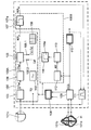
- FIG. 1 shows, as an embodiment of the invention, a rate adaptive pacemaker 100 as a fragmentary functional block diagram, in which only those for the Explanation of the invention important components are shown.
- the rest Structure corresponds to the well-known pacemaker.
- a pacemaker case electrode 101c serves as a counter electrode a pacemaker case electrode 101c.
- the impedance measurement is carried out in a manner known per se, by applying a measuring voltage U Z to a measuring voltage generator 102 and the current I Z (t m ) between the measuring electrode 101a and the counterelectrode at m equidistantly pre-programmed times t m via a current measuring circuit 103 101b is measured.
- the values Z (t m ) which characterize the time profile of the impedance result at the output of an impedance calculation stage 104 connected downstream of the current measurement circuit 103 as quotients from the (fixedly preset) measurement voltage and the measured current values.
- a primary rate control parameter value RCP p is calculated for each impedance time profile Z (t m ) detected.
- a predetermined modulation pattern with a relatively short period of a few cardiac cycles is stored in the pattern memory 107a, and at the output of the modulator stage 107 there is a variable according to the modulation pattern at each stimulation instant (" modulated ") RCP value RCP m available.
- the components 102 to 106 explained above form an impedance processing device 100A of the pacemaker 100 with which the sympathetic component is brought to bear at the CLS.
- a rate adaptation timer 108 controls both the one outlined above Impedance detection and evaluation in level 100A and the "fast" Modulation of the rate control signal in stage 107 as well as that below described acquisition and evaluation of the AV transition time (AVI).
- the Impedance measurement and AVI detection are carried out by the sequence control in Synchronicity to heart activity or pacemaker stimulation triggered.
- pacemaker conventionally comprises an IECG input stage 109 (which is shown in praxi can be formed by separate atrial and ventricular entrance stages), a Pacemaker operation control 1 10 and an output stage 111 (which is analogous to Entrance stage may include separate atrial and ventricular stages) and others components known per se. The general function of these components is here assumed to be known.
- the pacemaker either works in atrial stimulation mode - which is assumed below becomes - and the impedance is then evaluated on the natural ventricular event or mode changes are to be provided during calibration in order to on the one hand to be able to carry out the evaluation of the impedance at the VER and on the other hand, to have the natural AV interval available.
- the IECG input stage 109 is followed by an AVI acquisition stage 112, and the output of which leads to an AVI trend detection stage 113, which is an AVI memory 113a for a predetermined number of past AVI values (at least the penultimate value) and in which it is determined whether (and if necessary. in what form) a trend to extend or shorten the AVI compared to the previous cardiac cycle or cycles consists.
- an AVI trend detection stage 113 which is an AVI memory 113a for a predetermined number of past AVI values (at least the penultimate value) and in which it is determined whether (and if necessary. in what form) a trend to extend or shorten the AVI compared to the previous cardiac cycle or cycles consists.
- a correction or verification signal as a response factor control signal Cal determined and to the control input 105.2 of the RCP calculation stage 105 is transmitted.
- a output control signal immediately effective for the next cardiac cycle calibration.
- the decision matrix is a 2x2 matrix, in which the possibilities of an up or down modulated rate (RCP m > RCP p or RCP m ⁇ RCP p ) with the result of extended or shortened AV transition time (AVI ⁇ or AVI ⁇ ) are linked via four control signal fields, which contain one of the response factor control signals "Increase” (RF ⁇ ), "Decrease” (RF ⁇ ) or "Maintain” (RF ⁇ ): AVI
- This matrix takes into account the fact that the AV conduction time increases physiologically appropriate increasing rate shortened or with decreasing rate prolonged while "unphysiological" rate changes are just the opposite Provoke AVI behavior.
- the MCLR can also be calibrated: at high The patient's stress is - like in any other stressful state - the extension of the AVI indicating an unphysiological rate increase Trigger a reduction in the response factor, until no one appreciable increase in the stimulation rate occurs more, which is an effective upper rate limit results.
- the assemblies 107 and 112 to 114 form the calibration stage 100B of the Pacemaker with which the vagus component or the parasympathetic influence is brought to bear at the CLS.
- the signal connection of the pacemaker controller 110 to the intracardiac Electrodes 101a, 101b, with which cardiac actions or intracardiac EKGs are recorded Incidentally, a distinction between spontaneous and evoked heart actions and thus the consideration of the event type in the impedance based rate calculation.
- the calculated one Stimulation rate by the pacemaker control with every change of event type added a value from a plurality of internally stored rate offset values the amount of which depends on the previous and the current RCP value is chosen so that the rate jump does not exceed a predetermined amount exceeds, and in the subsequent cardiac events gradually up to is reduced to zero.
- the specific circuitry means for The person skilled in the art realizes this additional function from known arrangements for smoothing step functions of control variables, especially for Rate smoothing for pacemakers available.
- the embodiment of the invention is not limited to the above specified preferred embodiments. Rather is a number of Variants conceivable, which of the claimed solution also in a different kind Use execution.
- a position sensor can also be provided Signals using a suitable algorithm processing the impedance signal influence.
- a further modified version is in addition to the two closed loop sensors additionally an activity sensor or another "non-closed loop" sensor provided the breadth and reliability of the calibration algorithm can increase further and take over the rate control if necessary, if (for example due to disorders or a changed clinical picture) no automatic calibration of the CLS for a longer period of time according to the programmed Algorithm should be possible.
Landscapes
- Health & Medical Sciences (AREA)
- Heart & Thoracic Surgery (AREA)
- Cardiology (AREA)
- Life Sciences & Earth Sciences (AREA)
- Engineering & Computer Science (AREA)
- Physiology (AREA)
- Biophysics (AREA)
- Biomedical Technology (AREA)
- Nuclear Medicine, Radiotherapy & Molecular Imaging (AREA)
- Radiology & Medical Imaging (AREA)
- Animal Behavior & Ethology (AREA)
- General Health & Medical Sciences (AREA)
- Public Health (AREA)
- Veterinary Medicine (AREA)
- Electrotherapy Devices (AREA)
Applications Claiming Priority (2)
| Application Number | Priority Date | Filing Date | Title |
|---|---|---|---|
| DE19859653 | 1998-12-15 | ||
| DE19859653A DE19859653A1 (de) | 1998-12-15 | 1998-12-15 | Selbstkalibrierender ratenadaptiver Herzschrittmacher |
Publications (3)
| Publication Number | Publication Date |
|---|---|
| EP1013307A2 true EP1013307A2 (fr) | 2000-06-28 |
| EP1013307A3 EP1013307A3 (fr) | 2001-03-28 |
| EP1013307B1 EP1013307B1 (fr) | 2002-03-06 |
Family
ID=7892381
Family Applications (1)
| Application Number | Title | Priority Date | Filing Date |
|---|---|---|---|
| EP99250410A Expired - Lifetime EP1013307B1 (fr) | 1998-12-15 | 1999-11-20 | Stimulateur cardiaque à fréquence adaptable et à autocalibration |
Country Status (3)
| Country | Link |
|---|---|
| US (1) | US6463325B1 (fr) |
| EP (1) | EP1013307B1 (fr) |
| DE (2) | DE19859653A1 (fr) |
Families Citing this family (9)
| Publication number | Priority date | Publication date | Assignee | Title |
|---|---|---|---|---|
| DE19940952A1 (de) * | 1999-08-20 | 2001-02-22 | Biotronik Mess & Therapieg | Ratenadaptiver Herzschrittmacher |
| DE19963245A1 (de) * | 1999-12-17 | 2001-06-21 | Biotronik Mess & Therapieg | Herzschrittmacher mit Lagedetektor |
| DE10132228C1 (de) * | 2001-06-29 | 2003-04-03 | Karl Stangl | Herzschrittmacher mit periodischer Modulation einzelner Stimulationsintervalle |
| US7499750B2 (en) | 2003-04-11 | 2009-03-03 | Cardiac Pacemakers, Inc. | Noise canceling cardiac electrodes |
| US20060071479A1 (en) * | 2004-09-21 | 2006-04-06 | Norfolk Southern Corporation | Top-mounted container door system |
| US7996072B2 (en) | 2004-12-21 | 2011-08-09 | Cardiac Pacemakers, Inc. | Positionally adaptable implantable cardiac device |
| US8712522B1 (en) | 2005-10-18 | 2014-04-29 | Cvrx, Inc. | System for setting programmable parameters for an implantable hypertension treatment device |
| US20070118180A1 (en) * | 2005-11-18 | 2007-05-24 | Quan Ni | Cardiac resynchronization therapy for improved hemodynamics based on disordered breathing detection |
| US7599741B2 (en) | 2006-06-29 | 2009-10-06 | Cardiac Pacemakers, Inc. | Systems and methods for improving heart rate kinetics in heart failure patients |
Citations (6)
| Publication number | Priority date | Publication date | Assignee | Title |
|---|---|---|---|---|
| EP0147820A2 (fr) | 1983-12-27 | 1985-07-10 | Vitatron Medical B.V. | Entraîneur double cavité avec des moyens alternatifs de conformation à la fréquence |
| US5065759A (en) | 1990-08-30 | 1991-11-19 | Vitatron Medical B.V. | Pacemaker with optimized rate responsiveness and method of rate control |
| EP0498533A1 (fr) | 1991-02-05 | 1992-08-12 | Cardiac Pacemakers, Inc. | Stimulateur cardiaque à fréquence variable avec un fréquence supérieure de coupure qui dépend de l'état hémodynamique |
| WO1993020889A1 (fr) | 1992-04-17 | 1993-10-28 | Medtronic, Inc. | Procede et appareil de stimulation cardiaque sensible au rythme |
| DE19609382A1 (de) | 1996-03-04 | 1997-09-11 | Biotronik Mess & Therapieg | Aktivitätsgesteuerter Herzschrittmacher |
| DE19804843A1 (de) | 1998-01-29 | 1999-08-05 | Biotronik Mess & Therapieg | Selbstkalibrierender ratenadaptiver Herzschrittmacher |
Family Cites Families (13)
| Publication number | Priority date | Publication date | Assignee | Title |
|---|---|---|---|---|
| DE3533597A1 (de) * | 1985-09-18 | 1987-04-16 | Biotronik Mess & Therapieg | Herzschrittmacher |
| US5144950A (en) * | 1990-08-30 | 1992-09-08 | Vitatron Medical B.V. | Rate controlled pacemaker system using ar interval for rate control |
| US5111815A (en) * | 1990-10-15 | 1992-05-12 | Cardiac Pacemakers, Inc. | Method and apparatus for cardioverter/pacer utilizing neurosensing |
| US5154171A (en) * | 1991-06-15 | 1992-10-13 | Raul Chirife | Rate adaptive pacemaker controlled by ejection fraction |
| IT1259358B (it) * | 1992-03-26 | 1996-03-12 | Sorin Biomedica Spa | Dispositivo impiantabile per la rilevazione ed il controllo del tono simpatico-vagale |
| US5441525A (en) * | 1994-05-20 | 1995-08-15 | Medtronic, Inc. | Pacemaker with vasovagal syncope detection |
| DE4447447C2 (de) * | 1994-12-29 | 2000-07-06 | Pacesetter Ab Jaerfaella | Herzschrittmacher |
| US5487753A (en) * | 1995-03-16 | 1996-01-30 | Telectronics Pacing Systems, Inc. | Rate-responsive pacemaker with anaerobic threshold adaptation and method |
| DE69614413T2 (de) * | 1995-05-08 | 2002-06-20 | Pacesetter Ab, Jaerfaella | Therapievorrichtung zum erfassen der venösen blutströmung |
| US5749900A (en) * | 1995-12-11 | 1998-05-12 | Sulzer Intermedics Inc. | Implantable medical device responsive to heart rate variability analysis |
| US5690681A (en) * | 1996-03-29 | 1997-11-25 | Purdue Research Foundation | Method and apparatus using vagal stimulation for control of ventricular rate during atrial fibrillation |
| EP0804938B1 (fr) * | 1996-04-29 | 2004-07-07 | Pacesetter, Inc. | Stimulateur cardiaque à détermination du seuil anaérobique |
| DE19654494A1 (de) * | 1996-10-28 | 1998-05-07 | Biotronik Mess & Therapieg | Implantierbares Stimulationsgerät |
-
1998
- 1998-12-15 DE DE19859653A patent/DE19859653A1/de not_active Withdrawn
-
1999
- 1999-11-20 DE DE59900924T patent/DE59900924D1/de not_active Expired - Lifetime
- 1999-11-20 EP EP99250410A patent/EP1013307B1/fr not_active Expired - Lifetime
- 1999-12-15 US US09/464,674 patent/US6463325B1/en not_active Expired - Lifetime
Patent Citations (6)
| Publication number | Priority date | Publication date | Assignee | Title |
|---|---|---|---|---|
| EP0147820A2 (fr) | 1983-12-27 | 1985-07-10 | Vitatron Medical B.V. | Entraîneur double cavité avec des moyens alternatifs de conformation à la fréquence |
| US5065759A (en) | 1990-08-30 | 1991-11-19 | Vitatron Medical B.V. | Pacemaker with optimized rate responsiveness and method of rate control |
| EP0498533A1 (fr) | 1991-02-05 | 1992-08-12 | Cardiac Pacemakers, Inc. | Stimulateur cardiaque à fréquence variable avec un fréquence supérieure de coupure qui dépend de l'état hémodynamique |
| WO1993020889A1 (fr) | 1992-04-17 | 1993-10-28 | Medtronic, Inc. | Procede et appareil de stimulation cardiaque sensible au rythme |
| DE19609382A1 (de) | 1996-03-04 | 1997-09-11 | Biotronik Mess & Therapieg | Aktivitätsgesteuerter Herzschrittmacher |
| DE19804843A1 (de) | 1998-01-29 | 1999-08-05 | Biotronik Mess & Therapieg | Selbstkalibrierender ratenadaptiver Herzschrittmacher |
Also Published As
| Publication number | Publication date |
|---|---|
| DE59900924D1 (de) | 2002-04-11 |
| EP1013307B1 (fr) | 2002-03-06 |
| DE19859653A1 (de) | 2000-06-21 |
| EP1013307A3 (fr) | 2001-03-28 |
| US6463325B1 (en) | 2002-10-08 |
Similar Documents
| Publication | Publication Date | Title |
|---|---|---|
| DE69632853T2 (de) | Herzschrittmacher mit automatischer Funktion für die Austastzeit | |
| DE69233272T2 (de) | Verfahren und gerät zur energieregelung beim stimulieren in einem herzschrittmacher | |
| DE69824170T2 (de) | Ratenstabilisierender herzschrittmacher | |
| DE3486112T2 (de) | Zweikammer-Schrittmacher mit alternativen Mitteln zur Frequenzanpassung. | |
| DE69101547T2 (de) | Herzschrittmacher mit im Kreislauf platzierten Blutdruckaufnehmer zur Anzeige der Körperlage eines Patienten. | |
| DE68924951T2 (de) | Herzschrittmacher mit adaptiver Schrittfrequenz. | |
| DE69724952T2 (de) | Herzschrittmacher zur vorbeugung von arhythmie und fibrillation unter verwendung einer konsistenten herzreizung | |
| DE69823459T2 (de) | Herzbehandlungssystem zur Feststellung und Behandlung von Herzinsuffizienz | |
| DE69625262T2 (de) | Frequenzabhängiger Herzschrittmacher mit Adaptation an die anaerobe Schwelle | |
| DE69821850T2 (de) | Detektor zur Detektion der evozierten Reaktion und einen Herzschrittmacher mit einem solchen Detektor | |
| EP1062974B1 (fr) | Procédé de détermination d'un paramètre de commande variable d'un appareil médical implantable | |
| DE69727063T2 (de) | Implantierbares gerät | |
| DE3686713T3 (de) | System zur taktabhängigen Herzstimulierung. | |
| DE60220751T2 (de) | Herzschrittmacher mit verbesserter Einfangsbestätigung | |
| DE60301161T2 (de) | Vorrichtung zur Überwachung des Herzens und ein System beinhaltend eine solche Vorrichtung | |
| DE4447447C2 (de) | Herzschrittmacher | |
| DE69625925T2 (de) | Vorrichtung zur hämodynamischen stimulation bei einer ventrikulären tachykardie | |
| DE69028900T2 (de) | System und Verfahren zur Erhaltung der Reizimpulsamplitude bei Batterienentladung mittels selbstregulierender Stromaufnahme | |
| DE19804843A1 (de) | Selbstkalibrierender ratenadaptiver Herzschrittmacher | |
| DE602004005700T2 (de) | Gerät für die atrioventrikuläre suche | |
| EP1013307B1 (fr) | Stimulateur cardiaque à fréquence adaptable et à autocalibration | |
| DE19900690C1 (de) | Herzschrittmacher | |
| WO1989006990A1 (fr) | Circuit de regulation pour adapter la frequence de stimulation d'un stimulateur cardiaque a l'effort d'un patient | |
| DE69529326T2 (de) | Zweikammer-Herzschrittmacher-System mit verbesserter Umschaltung zwischen dem synchronen und dem asynchronen Modus | |
| DE69430155T2 (de) | Vorrichtung zur Stimulation des Herzens |
Legal Events
| Date | Code | Title | Description |
|---|---|---|---|
| PUAI | Public reference made under article 153(3) epc to a published international application that has entered the european phase |
Free format text: ORIGINAL CODE: 0009012 |
|
| AK | Designated contracting states |
Kind code of ref document: A2 Designated state(s): DE FR NL |
|
| AX | Request for extension of the european patent |
Free format text: AL;LT;LV;MK;RO;SI |
|
| PUAL | Search report despatched |
Free format text: ORIGINAL CODE: 0009013 |
|
| AK | Designated contracting states |
Kind code of ref document: A3 Designated state(s): AT BE CH CY DE DK ES FI FR GB GR IE IT LI LU MC NL PT SE |
|
| AX | Request for extension of the european patent |
Free format text: AL;LT;LV;MK;RO;SI |
|
| 17P | Request for examination filed |
Effective date: 20010511 |
|
| GRAG | Despatch of communication of intention to grant |
Free format text: ORIGINAL CODE: EPIDOS AGRA |
|
| 17Q | First examination report despatched |
Effective date: 20010807 |
|
| GRAG | Despatch of communication of intention to grant |
Free format text: ORIGINAL CODE: EPIDOS AGRA |
|
| GRAH | Despatch of communication of intention to grant a patent |
Free format text: ORIGINAL CODE: EPIDOS IGRA |
|
| AKX | Designation fees paid |
Free format text: DE FR NL |
|
| GRAH | Despatch of communication of intention to grant a patent |
Free format text: ORIGINAL CODE: EPIDOS IGRA |
|
| GRAA | (expected) grant |
Free format text: ORIGINAL CODE: 0009210 |
|
| AK | Designated contracting states |
Kind code of ref document: B1 Designated state(s): DE FR NL |
|
| REF | Corresponds to: |
Ref document number: 59900924 Country of ref document: DE Date of ref document: 20020411 |
|
| ET | Fr: translation filed | ||
| PLBE | No opposition filed within time limit |
Free format text: ORIGINAL CODE: 0009261 |
|
| STAA | Information on the status of an ep patent application or granted ep patent |
Free format text: STATUS: NO OPPOSITION FILED WITHIN TIME LIMIT |
|
| 26N | No opposition filed |
Effective date: 20021209 |
|
| PGFP | Annual fee paid to national office [announced via postgrant information from national office to epo] |
Ref country code: NL Payment date: 20081120 Year of fee payment: 10 |
|
| REG | Reference to a national code |
Ref country code: NL Ref legal event code: V1 Effective date: 20100601 |
|
| PG25 | Lapsed in a contracting state [announced via postgrant information from national office to epo] |
Ref country code: NL Free format text: LAPSE BECAUSE OF NON-PAYMENT OF DUE FEES Effective date: 20100601 |
|
| REG | Reference to a national code |
Ref country code: DE Ref legal event code: R082 Ref document number: 59900924 Country of ref document: DE |
|
| REG | Reference to a national code |
Ref country code: DE Ref legal event code: R081 Ref document number: 59900924 Country of ref document: DE Owner name: BIOTRONIK SE & CO. KG, DE Free format text: FORMER OWNER: BIOTRONIK MESS- UND THERAPIEGERAETE GMBH & CO. INGENIEURBUERO BERLIN, 12359 BERLIN, DE Effective date: 20111219 |
|
| PGFP | Annual fee paid to national office [announced via postgrant information from national office to epo] |
Ref country code: DE Payment date: 20121109 Year of fee payment: 14 |
|
| PGFP | Annual fee paid to national office [announced via postgrant information from national office to epo] |
Ref country code: FR Payment date: 20121217 Year of fee payment: 14 |
|
| REG | Reference to a national code |
Ref country code: FR Ref legal event code: ST Effective date: 20140731 |
|
| PG25 | Lapsed in a contracting state [announced via postgrant information from national office to epo] |
Ref country code: DE Free format text: LAPSE BECAUSE OF NON-PAYMENT OF DUE FEES Effective date: 20140603 |
|
| REG | Reference to a national code |
Ref country code: DE Ref legal event code: R119 Ref document number: 59900924 Country of ref document: DE Effective date: 20140603 |
|
| PG25 | Lapsed in a contracting state [announced via postgrant information from national office to epo] |
Ref country code: FR Free format text: LAPSE BECAUSE OF NON-PAYMENT OF DUE FEES Effective date: 20131202 |