EP1013374A2 - Machine-outil avec broche travaillant par le bas - Google Patents
Machine-outil avec broche travaillant par le bas Download PDFInfo
- Publication number
- EP1013374A2 EP1013374A2 EP99123819A EP99123819A EP1013374A2 EP 1013374 A2 EP1013374 A2 EP 1013374A2 EP 99123819 A EP99123819 A EP 99123819A EP 99123819 A EP99123819 A EP 99123819A EP 1013374 A2 EP1013374 A2 EP 1013374A2
- Authority
- EP
- European Patent Office
- Prior art keywords
- machine tool
- tool
- tool according
- machine
- chip
- Prior art date
- Legal status (The legal status is an assumption and is not a legal conclusion. Google has not performed a legal analysis and makes no representation as to the accuracy of the status listed.)
- Granted
Links
Images

Classifications
-
- B—PERFORMING OPERATIONS; TRANSPORTING
- B23—MACHINE TOOLS; METAL-WORKING NOT OTHERWISE PROVIDED FOR
- B23Q—DETAILS, COMPONENTS, OR ACCESSORIES FOR MACHINE TOOLS, e.g. ARRANGEMENTS FOR COPYING OR CONTROLLING; MACHINE TOOLS IN GENERAL CHARACTERISED BY THE CONSTRUCTION OF PARTICULAR DETAILS OR COMPONENTS; COMBINATIONS OR ASSOCIATIONS OF METAL-WORKING MACHINES, NOT DIRECTED TO A PARTICULAR RESULT
- B23Q11/00—Accessories fitted to machine tools for keeping tools or parts of the machine in good working condition or for cooling work; Safety devices specially combined with or arranged in, or specially adapted for use in connection with, machine tools
- B23Q11/0042—Devices for removing chips
- B23Q11/0053—Devices for removing chips using the gravity force
-
- B—PERFORMING OPERATIONS; TRANSPORTING
- B23—MACHINE TOOLS; METAL-WORKING NOT OTHERWISE PROVIDED FOR
- B23Q—DETAILS, COMPONENTS, OR ACCESSORIES FOR MACHINE TOOLS, e.g. ARRANGEMENTS FOR COPYING OR CONTROLLING; MACHINE TOOLS IN GENERAL CHARACTERISED BY THE CONSTRUCTION OF PARTICULAR DETAILS OR COMPONENTS; COMBINATIONS OR ASSOCIATIONS OF METAL-WORKING MACHINES, NOT DIRECTED TO A PARTICULAR RESULT
- B23Q1/00—Members which are comprised in the general build-up of a form of machine, particularly relatively large fixed members
- B23Q1/25—Movable or adjustable work or tool supports
- B23Q1/44—Movable or adjustable work or tool supports using particular mechanisms
- B23Q1/48—Movable or adjustable work or tool supports using particular mechanisms with sliding pairs and rotating pairs
- B23Q1/4876—Movable or adjustable work or tool supports using particular mechanisms with sliding pairs and rotating pairs a single sliding pair followed parallelly by a single rotating pair
- B23Q1/4885—Movable or adjustable work or tool supports using particular mechanisms with sliding pairs and rotating pairs a single sliding pair followed parallelly by a single rotating pair followed parallelly by a single rotating pair
-
- B—PERFORMING OPERATIONS; TRANSPORTING
- B23—MACHINE TOOLS; METAL-WORKING NOT OTHERWISE PROVIDED FOR
- B23Q—DETAILS, COMPONENTS, OR ACCESSORIES FOR MACHINE TOOLS, e.g. ARRANGEMENTS FOR COPYING OR CONTROLLING; MACHINE TOOLS IN GENERAL CHARACTERISED BY THE CONSTRUCTION OF PARTICULAR DETAILS OR COMPONENTS; COMBINATIONS OR ASSOCIATIONS OF METAL-WORKING MACHINES, NOT DIRECTED TO A PARTICULAR RESULT
- B23Q1/00—Members which are comprised in the general build-up of a form of machine, particularly relatively large fixed members
- B23Q1/25—Movable or adjustable work or tool supports
- B23Q1/44—Movable or adjustable work or tool supports using particular mechanisms
- B23Q1/50—Movable or adjustable work or tool supports using particular mechanisms with rotating pairs only, the rotating pairs being the first two elements of the mechanism
-
- B—PERFORMING OPERATIONS; TRANSPORTING
- B23—MACHINE TOOLS; METAL-WORKING NOT OTHERWISE PROVIDED FOR
- B23Q—DETAILS, COMPONENTS, OR ACCESSORIES FOR MACHINE TOOLS, e.g. ARRANGEMENTS FOR COPYING OR CONTROLLING; MACHINE TOOLS IN GENERAL CHARACTERISED BY THE CONSTRUCTION OF PARTICULAR DETAILS OR COMPONENTS; COMBINATIONS OR ASSOCIATIONS OF METAL-WORKING MACHINES, NOT DIRECTED TO A PARTICULAR RESULT
- B23Q1/00—Members which are comprised in the general build-up of a form of machine, particularly relatively large fixed members
- B23Q1/25—Movable or adjustable work or tool supports
- B23Q1/44—Movable or adjustable work or tool supports using particular mechanisms
- B23Q1/50—Movable or adjustable work or tool supports using particular mechanisms with rotating pairs only, the rotating pairs being the first two elements of the mechanism
- B23Q1/52—Movable or adjustable work or tool supports using particular mechanisms with rotating pairs only, the rotating pairs being the first two elements of the mechanism a single rotating pair
-
- B—PERFORMING OPERATIONS; TRANSPORTING
- B23—MACHINE TOOLS; METAL-WORKING NOT OTHERWISE PROVIDED FOR
- B23Q—DETAILS, COMPONENTS, OR ACCESSORIES FOR MACHINE TOOLS, e.g. ARRANGEMENTS FOR COPYING OR CONTROLLING; MACHINE TOOLS IN GENERAL CHARACTERISED BY THE CONSTRUCTION OF PARTICULAR DETAILS OR COMPONENTS; COMBINATIONS OR ASSOCIATIONS OF METAL-WORKING MACHINES, NOT DIRECTED TO A PARTICULAR RESULT
- B23Q11/00—Accessories fitted to machine tools for keeping tools or parts of the machine in good working condition or for cooling work; Safety devices specially combined with or arranged in, or specially adapted for use in connection with, machine tools
- B23Q11/08—Protective coverings for parts of machine tools; Splash guards
-
- B—PERFORMING OPERATIONS; TRANSPORTING
- B23—MACHINE TOOLS; METAL-WORKING NOT OTHERWISE PROVIDED FOR
- B23Q—DETAILS, COMPONENTS, OR ACCESSORIES FOR MACHINE TOOLS, e.g. ARRANGEMENTS FOR COPYING OR CONTROLLING; MACHINE TOOLS IN GENERAL CHARACTERISED BY THE CONSTRUCTION OF PARTICULAR DETAILS OR COMPONENTS; COMBINATIONS OR ASSOCIATIONS OF METAL-WORKING MACHINES, NOT DIRECTED TO A PARTICULAR RESULT
- B23Q3/00—Devices holding, supporting, or positioning work or tools, of a kind normally removable from the machine
- B23Q3/155—Arrangements for automatic insertion or removal of tools, e.g. combined with manual handling
- B23Q3/1552—Arrangements for automatic insertion or removal of tools, e.g. combined with manual handling parts of devices for automatically inserting or removing tools
- B23Q3/15526—Storage devices; Drive mechanisms therefor
- B23Q3/15536—Non-rotary fixed racks
-
- B—PERFORMING OPERATIONS; TRANSPORTING
- B23—MACHINE TOOLS; METAL-WORKING NOT OTHERWISE PROVIDED FOR
- B23Q—DETAILS, COMPONENTS, OR ACCESSORIES FOR MACHINE TOOLS, e.g. ARRANGEMENTS FOR COPYING OR CONTROLLING; MACHINE TOOLS IN GENERAL CHARACTERISED BY THE CONSTRUCTION OF PARTICULAR DETAILS OR COMPONENTS; COMBINATIONS OR ASSOCIATIONS OF METAL-WORKING MACHINES, NOT DIRECTED TO A PARTICULAR RESULT
- B23Q3/00—Devices holding, supporting, or positioning work or tools, of a kind normally removable from the machine
- B23Q3/155—Arrangements for automatic insertion or removal of tools, e.g. combined with manual handling
- B23Q3/157—Arrangements for automatic insertion or removal of tools, e.g. combined with manual handling of rotary tools
- B23Q3/15706—Arrangements for automatic insertion or removal of tools, e.g. combined with manual handling of rotary tools a single tool being inserted in a spindle directly from a storage device, i.e. without using transfer devices
-
- Y—GENERAL TAGGING OF NEW TECHNOLOGICAL DEVELOPMENTS; GENERAL TAGGING OF CROSS-SECTIONAL TECHNOLOGIES SPANNING OVER SEVERAL SECTIONS OF THE IPC; TECHNICAL SUBJECTS COVERED BY FORMER USPC CROSS-REFERENCE ART COLLECTIONS [XRACs] AND DIGESTS
- Y10—TECHNICAL SUBJECTS COVERED BY FORMER USPC
- Y10T—TECHNICAL SUBJECTS COVERED BY FORMER US CLASSIFICATION
- Y10T408/00—Cutting by use of rotating axially moving tool
- Y10T408/91—Machine frame
-
- Y—GENERAL TAGGING OF NEW TECHNOLOGICAL DEVELOPMENTS; GENERAL TAGGING OF CROSS-SECTIONAL TECHNOLOGIES SPANNING OVER SEVERAL SECTIONS OF THE IPC; TECHNICAL SUBJECTS COVERED BY FORMER USPC CROSS-REFERENCE ART COLLECTIONS [XRACs] AND DIGESTS
- Y10—TECHNICAL SUBJECTS COVERED BY FORMER USPC
- Y10T—TECHNICAL SUBJECTS COVERED BY FORMER US CLASSIFICATION
- Y10T409/00—Gear cutting, milling, or planing
- Y10T409/30—Milling
- Y10T409/304536—Milling including means to infeed work to cutter
- Y10T409/305544—Milling including means to infeed work to cutter with work holder
-
- Y—GENERAL TAGGING OF NEW TECHNOLOGICAL DEVELOPMENTS; GENERAL TAGGING OF CROSS-SECTIONAL TECHNOLOGIES SPANNING OVER SEVERAL SECTIONS OF THE IPC; TECHNICAL SUBJECTS COVERED BY FORMER USPC CROSS-REFERENCE ART COLLECTIONS [XRACs] AND DIGESTS
- Y10—TECHNICAL SUBJECTS COVERED BY FORMER USPC
- Y10T—TECHNICAL SUBJECTS COVERED BY FORMER US CLASSIFICATION
- Y10T409/00—Gear cutting, milling, or planing
- Y10T409/30—Milling
- Y10T409/306664—Milling including means to infeed rotary cutter toward work
- Y10T409/307672—Angularly adjustable cutter head
-
- Y—GENERAL TAGGING OF NEW TECHNOLOGICAL DEVELOPMENTS; GENERAL TAGGING OF CROSS-SECTIONAL TECHNOLOGIES SPANNING OVER SEVERAL SECTIONS OF THE IPC; TECHNICAL SUBJECTS COVERED BY FORMER USPC CROSS-REFERENCE ART COLLECTIONS [XRACs] AND DIGESTS
- Y10—TECHNICAL SUBJECTS COVERED BY FORMER USPC
- Y10T—TECHNICAL SUBJECTS COVERED BY FORMER US CLASSIFICATION
- Y10T409/00—Gear cutting, milling, or planing
- Y10T409/30—Milling
- Y10T409/30784—Milling including means to adustably position cutter
- Y10T409/307952—Linear adjustment
- Y10T409/308232—Linear adjustment and angular adjustment
-
- Y—GENERAL TAGGING OF NEW TECHNOLOGICAL DEVELOPMENTS; GENERAL TAGGING OF CROSS-SECTIONAL TECHNOLOGIES SPANNING OVER SEVERAL SECTIONS OF THE IPC; TECHNICAL SUBJECTS COVERED BY FORMER USPC CROSS-REFERENCE ART COLLECTIONS [XRACs] AND DIGESTS
- Y10—TECHNICAL SUBJECTS COVERED BY FORMER USPC
- Y10T—TECHNICAL SUBJECTS COVERED BY FORMER US CLASSIFICATION
- Y10T409/00—Gear cutting, milling, or planing
- Y10T409/30—Milling
- Y10T409/30784—Milling including means to adustably position cutter
- Y10T409/308512—Compound angular adjustment
-
- Y—GENERAL TAGGING OF NEW TECHNOLOGICAL DEVELOPMENTS; GENERAL TAGGING OF CROSS-SECTIONAL TECHNOLOGIES SPANNING OVER SEVERAL SECTIONS OF THE IPC; TECHNICAL SUBJECTS COVERED BY FORMER USPC CROSS-REFERENCE ART COLLECTIONS [XRACs] AND DIGESTS
- Y10—TECHNICAL SUBJECTS COVERED BY FORMER USPC
- Y10T—TECHNICAL SUBJECTS COVERED BY FORMER US CLASSIFICATION
- Y10T409/00—Gear cutting, milling, or planing
- Y10T409/30—Milling
- Y10T409/30868—Work support
- Y10T409/309016—Work support with work holder or guide
-
- Y—GENERAL TAGGING OF NEW TECHNOLOGICAL DEVELOPMENTS; GENERAL TAGGING OF CROSS-SECTIONAL TECHNOLOGIES SPANNING OVER SEVERAL SECTIONS OF THE IPC; TECHNICAL SUBJECTS COVERED BY FORMER USPC CROSS-REFERENCE ART COLLECTIONS [XRACs] AND DIGESTS
- Y10—TECHNICAL SUBJECTS COVERED BY FORMER USPC
- Y10T—TECHNICAL SUBJECTS COVERED BY FORMER US CLASSIFICATION
- Y10T483/00—Tool changing
- Y10T483/17—Tool changing including machine tool or component
- Y10T483/1733—Rotary spindle machine tool [e.g., milling machine, boring, machine, grinding machine, etc.]
- Y10T483/1736—Tool having specific mounting or work treating feature
-
- Y—GENERAL TAGGING OF NEW TECHNOLOGICAL DEVELOPMENTS; GENERAL TAGGING OF CROSS-SECTIONAL TECHNOLOGIES SPANNING OVER SEVERAL SECTIONS OF THE IPC; TECHNICAL SUBJECTS COVERED BY FORMER USPC CROSS-REFERENCE ART COLLECTIONS [XRACs] AND DIGESTS
- Y10—TECHNICAL SUBJECTS COVERED BY FORMER USPC
- Y10T—TECHNICAL SUBJECTS COVERED BY FORMER US CLASSIFICATION
- Y10T483/00—Tool changing
- Y10T483/17—Tool changing including machine tool or component
- Y10T483/1733—Rotary spindle machine tool [e.g., milling machine, boring, machine, grinding machine, etc.]
- Y10T483/179—Direct tool exchange between spindle and matrix
- Y10T483/1793—Spindle comprises tool changer
Definitions
- the present invention relates to a machine tool a workpiece table for fixing workpieces to be machined and a tool spindle with a tool holder for tools for machining the workpieces.
- the known machine tools generally have a vertical axis Tool spindle on that above a workpiece table is arranged on which the workpieces to be machined can be fixed by means of clamping devices.
- the tool spindle and the workpiece table are in with each other three orthogonal axes, so that the top of the Workpiece are machined in a known manner can.
- cooling lubricant is used to ensure that the Use the tool and the workpiece to cool and to remove the resulting chips.
- cooling lubricant is associated with major problems, so that efforts have been underway for some time to operate the known machine tools with what is known as minimum quantity lubrication, as is known per se from the prior art. In such systems with minimal quantity lubrication, only one cm 3 of cooling lubricant is used per hour, which is technically manageable with new tool geometries and coatings. However, there are problems with the hot chips.
- this object is achieved in the above-mentioned Machine tool solved in that the machine tool with in the operating position with the tool pointing upwards.
- the inventor of the present application has recognized that that by moving away from the usual machine concept and by choosing an "overhead processing" a free chip fall is possible so that the chips are no longer on the workpiece or the workpiece table or its guide rails remain can be removed directly into the chip tray are.
- This new machine concept now also enables one Dry machining or machining with minimal quantity lubrication, the cooling lubricant is no longer required, to remove the resulting chips. Because the hot shavings too no longer on the workpiece or in the area of the workpiece table can remain there are no thermal Deflections in this area, so that the cooling effect of the Cooling lubricant is no longer required in the previous dimensions.
- the new machine tool concept is dry machining or machining with minimal quantity lubrication without having to Dry machining or minimum quantity lubrication in the state of Technology problems still adversely affect can.
- the chips are no longer wetted with cooling lubricant, so that they do not fall off the workpiece on preferably vertical structures of the new ones Machine tool can stick.
- the dry chips rather fall directly over suitable baffles into the chip tub.
- the chip pan is however by now very hot chips heated up much more than at the beginning mentioned machine tool. The temperatures that arise here can be mastered by e.g. the chip pan is thermally insulated from the hot chips, whereby thermal deflections of the machine tool itself avoided become.
- the tool spindle with the tool holder pointing upwards on at least one Sliding mechanisms partially arranged below the workpiece table is mounted, which is preferably at least one lever gear includes that around a vertical formed by a hinge Axis swiveling on a machine frame of the machine tool is stored.
- lever mechanism two around a joint vertically aligned panels that can be swiveled against each other has, one of which with the tool spindle and the another is connected to the machine frame.
- this measure is constructive with regard to the Machining accuracy is an advantage because the plates of the lever gear ensure a very stiff sliding mechanism, so that the tool spindle overhanging the lever gear directly on the machine frame below or behind the workpiece table can be stored. It is preferred if Two lever gears are provided, which in turn are adjustable in height are attached to the machine frame. To this On the one hand, a very high degree of rigidity and tipping safety becomes reached, the other being the vertical one Guide rail offers little contact surfaces on which the resulting chips can remain.
- joints with cover caps to protect against chips and preferably the plates have chip deflection surfaces on their upper narrow sides.
- the workpiece table is one of device accessible below for fixing the workpieces and preferably two horizontally and parallel to each other has extending supports on which the device by horizontal axis is pivotally arranged.
- This measure has the advantage that the workpiece table in The area of the device is, so to speak, open at the bottom, so that the free chip fall is not hindered. But it enables also convenient operation of the new machine tool, because to change the workpiece, the device, which according to Art a cradle plate can be formed only around the horizontal Axis pivoted through 180 ° so that the finished machined Workpiece now lies on top of the workpiece table. The operator can now easily remove this workpiece and clamp a new workpiece.
- Another advantage of the new machine tool is there too see that this has a significantly lower height, because previously used for the sliding mechanism of the tool spindle above space of the workpiece table is no longer required, the sliding mechanism is rather in the previously unused space below the workpiece table.
- the new machine tool is also significantly more compact than known machine tools.
- Chip deflector plate running diagonally downwards and forwards is, preferably below the sliding mechanism a chip collection funnel is arranged, the resulting chips in a chip tub leads.
- the Chip deflector lies because of its slanted forward and down inclined position between the top of the vertical Guide rails and slides on which the lever gear be moved vertically, and the workpiece, i.e. the source the resulting chips. In this way the sliding mechanism effectively protected against chips.
- the tool change takes place but usually with an additional tool changing device, which are equipped with grippers and swivel arms and tools between the tool magazine and the tool holder the spindle changes.
- the tool magazine is included arranged clearly above the workpiece table in order to Soiling of the tools held in stock by flying around Prevent chips or spraying coolant.
- the tool changing device is in this context required to remove the tools, so to speak, and insert into the bottom of the spindle.
- the tool magazine can be above be arranged on the plane of the workpiece table so that a Contamination of the tools in stock is prevented becomes.
- the new machine concept also enables to do without the tool changer without having to change the position the advantage given to technology is lost in that the tools in their storage position are not soiled.
- the machine tool 10 denotes a machine tool, which is shown in the top view.
- the machine tool 10 comprises a workpiece table 11 on which a workpiece to be machined Workpiece 12 fixed in a manner to be described is.
- a tool spindle 14 is also provided in the tool holder 15 a tool 16 for machining the workpiece 12 is arranged.
- the machine tool 10 further comprises a machine frame 17 on which both the workpiece table 11 as well as the tool spindle to be described 14 is stored.
- the workpiece table 11 comprises two parallel to each other and horizontally extending beams 18, 19 directly on the machine frame 17 are attached.
- a device 21 for fixing is between the supports 18, 19 of the workpiece 12 to be machined.
- the device 21 comprises a cradle plate 22 which is arranged around a horizontal axis is pivotable.
- In the in 1 shows the workpiece 12 upwards, that is towards the viewer.
- clamping parts 24 recognizable, which are provided on the cradle plate 22 and that Clamp workpiece 12 between them.
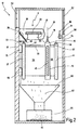
- a displacement mechanism is located below the workpiece table 11 28 provided for the tool spindle 14, this geometric Assignment better from FIG. 2, which will be described later emerges.
- the displacement mechanism 28 comprises two lever gears 29, 31 which Height-adjustable via guide rails 32, 33 and slide 34, 35 are mounted on the machine frame 17.
- the lever gear 29, 31 are about joints 36, 37 around a horizontal Axis pivotally mounted on the machine frame 18.
- the lever gears 29, 31 each comprise a first plate 38, 39, which can be pivoted according to an arrow 41 or 42 the carriage 34 or 35 is mounted.
- they are Plates 38, 39 connected with joints 43, 44, on which also second plates 45, 46 of the lever gear 29, 31 articulated are.
- the second plates 45, 46 At the other end are the second plates 45, 46 with the Tool spindle 14 connected.
- the first and second plates 38 and 45 or 39 and 46 can are pivoted towards each other, as indicated by arrows 47 and 48 is indicated.
- the second plates 45, 46 are also articulated mounted on the tool spindle 14, as indicated by an arrow 49 is shown.
- the machine tool 10 has on the front side in FIG. 1 another tool magazine 50 with storage spaces 51 for replaceable Tools 16 on.
- the tool spindle 14 can have any storage space 51 approach in the tool magazine 50 and thus on Put down used tool 16 and take out a new tool 16.
- a door 52 is provided for loading the tool magazine 50, by the operating personnel empty the storage spaces 51 and can re-equip.
- the machine tool 10 has on the opposite side another door 53 through which a machined workpiece 12 removed and a workpiece 12 to be machined inserted can be.
- the cradle plate is in place during this removal work 22 in the position shown in FIG. 1.
- the weighing plate 22 is then around the axis 23 Swiveled 180 ° so that it the position shown in Fig. 2 occupies, namely in the workpiece 12 down on the Assigns tool spindle 14.
- Fig. 2 top right it can be seen that the storage space 51 of the tool magazine 50 with one pointing upwards Tool 16 is occupied, the other end a usual Has steep taper or hollow shaft taper 54.
- the chip deflector is now better above the guide rail 33 26 to recognize that in Fig. 2 obliquely downwards extends right and thus an effective protection against chips offers that arise during the machining of the workpiece 12 and jump sideways and down.
- the chip deflector 26 thus protects the guide rails 32, 33 and on them running sled 34, 35, 55 from chip infestation and corresponding Damage or heating.
- the plates 38, 39, 45, 46 have on their upper narrow sides 56 chip deflection surfaces 57, in the simplest case in cross section are semicircular, as cut at the plate 45 shown above can be clearly seen.
- the joints 36, 37, 43, 44 are provided with cover caps 58 at the top, so that the vertical surfaces of the joints are protected from chips are.
- the tool spindle 14 is also rounded off at its upper end 59 designed to prevent chips from getting caught.
- the machine tool 10 is for dry machining or machining provided with minimal quantity lubrication, with so little Coolant is used that the resulting Chips 62 neither wetted with cooling lubricant nor cooled thereby become.
- the resulting hot chips 62 are by the Chip deflector plate 26, the chip deflector surfaces 57 and the cover caps 58 directed downward in FIG. 2, stopping on the joints 36, 37, 43, 44 or plates 38, 39, 45, 46 or even the guide rails 32, 33 becomes effective in this way prevented.
- the resulting hot chips 62 become immediate over the chip collecting funnel 63 into the chip pan 64 headed. Because the chips are not wetted with coolant they can also be on the essentially vertical surfaces the plates 38, 39, 45, 46 and joints 36, 37, 43, 44 and Do not stick tool spindle 14 and stick.
- All hot chips 62 collect in the chip tray 64, which is protected against heating by insulation 65.
Landscapes
- Engineering & Computer Science (AREA)
- Mechanical Engineering (AREA)
- Machine Tool Units (AREA)
- Jigs For Machine Tools (AREA)
Applications Claiming Priority (2)
| Application Number | Priority Date | Filing Date | Title |
|---|---|---|---|
| DE19859662A DE19859662C2 (de) | 1998-12-23 | 1998-12-23 | Werkzeugmaschine mit von unten arbeitender Werkzeugspindel |
| DE19859662 | 1998-12-23 |
Publications (3)
| Publication Number | Publication Date |
|---|---|
| EP1013374A2 true EP1013374A2 (fr) | 2000-06-28 |
| EP1013374A3 EP1013374A3 (fr) | 2003-06-04 |
| EP1013374B1 EP1013374B1 (fr) | 2009-04-01 |
Family
ID=7892385
Family Applications (1)
| Application Number | Title | Priority Date | Filing Date |
|---|---|---|---|
| EP99123819A Expired - Lifetime EP1013374B1 (fr) | 1998-12-23 | 1999-12-01 | Machine-outil avec broche travaillant par le bas |
Country Status (4)
| Country | Link |
|---|---|
| US (1) | US6387026B1 (fr) |
| EP (1) | EP1013374B1 (fr) |
| DE (1) | DE19859662C2 (fr) |
| ES (1) | ES2322519T3 (fr) |
Families Citing this family (12)
| Publication number | Priority date | Publication date | Assignee | Title |
|---|---|---|---|---|
| US8210318B2 (en) * | 2006-04-04 | 2012-07-03 | Haas Automation, Inc. | Minimum oil machining system |
| RU2434730C2 (ru) * | 2006-09-21 | 2011-11-27 | Эрбюс Операсьон (Сас) | Устройство для обработки снизу неподвижно закрепленных деталей |
| US8333536B2 (en) * | 2009-10-09 | 2012-12-18 | Shenq Fang Yuan Technology Co., Ltd. | Multi-spindle machining machine |
| US8308621B2 (en) * | 2009-10-13 | 2012-11-13 | Shenq Fang Yuan Technology Co., Ltd. | Multi-spindle machining machine with tool changing mechanism |
| DE102010054393A1 (de) * | 2010-12-07 | 2012-06-14 | Chiron-Werke Gmbh & Co. Kg | Verfahren zur Bestimmung der Position eines Werkzeuges |
| DE102012018226B4 (de) * | 2012-09-15 | 2024-03-28 | Emag Holding Gmbh | Werkzeugmaschine mit Schutzabdeckung |
| US8974358B2 (en) * | 2012-10-04 | 2015-03-10 | Shenq Fang Yuan Technology Co., Ltd. | Multi-spindle machining machine with tool changing mechanism |
| JP6391967B2 (ja) * | 2014-03-31 | 2018-09-19 | Dmg森精機株式会社 | 工作機械 |
| JP6533708B2 (ja) * | 2015-07-21 | 2019-06-19 | オークマ株式会社 | 工作機械 |
| US11052498B2 (en) | 2018-05-14 | 2021-07-06 | Modig Machine Tool US Inc. | Invertible part loading system |
| CN108746784A (zh) * | 2018-06-28 | 2018-11-06 | 宁德思客琦智能装备有限公司 | 一种锂电池电芯极柱面铣削设备 |
| ES3015726T3 (en) * | 2021-01-22 | 2025-05-07 | Modig Machine Tools Ab | A machining device for machining a workpiece and a method thereof |
Family Cites Families (24)
| Publication number | Priority date | Publication date | Assignee | Title |
|---|---|---|---|---|
| DE307739C (fr) * | ||||
| US2989901A (en) * | 1959-11-03 | 1961-06-27 | John D Bohannon | Automatic hinge recess routing machine for spectacle frames |
| US4275777A (en) * | 1979-10-15 | 1981-06-30 | Briggs Louis H | Table saw carriage attachment |
| US4524812A (en) * | 1982-08-11 | 1985-06-25 | Murphy Peter H | Modulated forming machine |
| FR2560541B1 (fr) * | 1984-03-02 | 1987-06-26 | Sateco Sarl | Machine executant diverses operations d'usinage, telles que tournage, fraisage, alesage |
| CH660993A5 (fr) * | 1984-10-16 | 1987-06-30 | Greub Jean Sa | Procede d'usinage d'une piece et machine-outil modulaire pour la mise en oeuvre de ce procede. |
| GB2167325B (en) * | 1984-11-22 | 1987-08-26 | Wavis Engineering Dev Co Limit | Multi-spindle machining centre |
| FR2585276B2 (fr) * | 1985-07-26 | 1987-11-13 | Sateco Sarl | Machine executant diverses operations d'usinage telles que tournage, fraisage, alesage |
| US4830554A (en) * | 1986-06-23 | 1989-05-16 | Cencorp, Inc. | Routing apparatus for cutting printed circuit boards |
| JPH0215945A (ja) * | 1988-06-30 | 1990-01-19 | Ahresty Corp | 工作機械 |
| DE3931075A1 (de) * | 1989-09-18 | 1991-03-28 | Voest Alpine Mach Const | Vorrichtung zur unterwasserbearbeitung eines strahlenden werkstueckes |
| JPH0413504A (ja) * | 1990-04-28 | 1992-01-17 | Yoshio Fujino | プリント配線板の穴あけ加工に適したボール盤 |
| DE4117723A1 (de) * | 1990-06-02 | 1991-12-05 | Waldrich Werkzeugmasch | Arbeitsmaschine zur behandlung von werkstuecken, insbesondere werkzeugmaschine |
| US5267818A (en) * | 1991-08-05 | 1993-12-07 | Optima Industries, Inc. | Arrangement for providing planar movement of a machine tool |
| AU657852B2 (en) * | 1992-04-10 | 1995-03-23 | Emag Holding Gmbh | Machining centre constructed from assemblies |
| DE4435024C2 (de) * | 1994-09-26 | 1997-04-24 | Hektor Steinhilber | Bohr- und Fräsmaschine mit verfahrbarer Werkstückspannvorrichtung |
| DE4441252B4 (de) * | 1994-11-19 | 2006-01-26 | Maschinenfabrik Berthold Hermle Ag | Werkzeugmaschine, insbesondere Bohr- und Fräsmaschine |
| DE19521846B4 (de) * | 1995-06-16 | 2005-06-16 | Gildemeister Ag | Numerisch gesteuerte Bearbeitungsmaschine |
| JP3626265B2 (ja) * | 1995-12-18 | 2005-03-02 | 本田技研工業株式会社 | 工作機械 |
| DE19623511A1 (de) * | 1996-06-13 | 1997-12-18 | Vdw Ev | Vorrichtung zur Bearbeitung und/oder Montage von Werkstücken |
| EP0820835B1 (fr) * | 1996-07-26 | 2001-02-28 | GROB-Werke Dr. h.c. mult. Dipl.-Ing. Burkhart Grob e.K. | Centre d'usinage |
| WO1998004383A1 (fr) * | 1996-07-29 | 1998-02-05 | Matsushita Electric Industrial Co., Ltd. | Machine-outil |
| JPH1086038A (ja) * | 1996-09-13 | 1998-04-07 | Toyoda Mach Works Ltd | 工作物の加工方法およびそのための工作機械 |
| US5832783A (en) * | 1996-10-22 | 1998-11-10 | Sheldon/Van Someren Inc. | Three-axis machine structure |
-
1998
- 1998-12-23 DE DE19859662A patent/DE19859662C2/de not_active Expired - Fee Related
-
1999
- 1999-12-01 ES ES99123819T patent/ES2322519T3/es not_active Expired - Lifetime
- 1999-12-01 EP EP99123819A patent/EP1013374B1/fr not_active Expired - Lifetime
- 1999-12-16 US US09/465,114 patent/US6387026B1/en not_active Expired - Fee Related
Also Published As
| Publication number | Publication date |
|---|---|
| ES2322519T3 (es) | 2009-06-22 |
| EP1013374B1 (fr) | 2009-04-01 |
| US6387026B1 (en) | 2002-05-14 |
| EP1013374A3 (fr) | 2003-06-04 |
| DE19859662C2 (de) | 2003-06-12 |
| DE19859662A1 (de) | 2000-07-06 |
Similar Documents
| Publication | Publication Date | Title |
|---|---|---|
| DE19918359C2 (de) | Werkzeugmaschine mit einer Arbeitsraumabdeckung | |
| DE19646189C2 (de) | Maschine zum Herstellen von bogenverzahnten Kegelrädern | |
| DE69718324T2 (de) | Werkzeugmaschine | |
| DE102006024407B4 (de) | Werkzeugmaschine | |
| EP1034875B1 (fr) | Machine-outil pour l'usinage avec outils de coupe et laser | |
| DE102004046996B4 (de) | Werkzeugmaschine | |
| EP2747936B1 (fr) | Machine-outil | |
| EP2185317B1 (fr) | Machine-outil comprenant au moins une porte coulissante | |
| EP1013374B1 (fr) | Machine-outil avec broche travaillant par le bas | |
| EP0452735A1 (fr) | Centre d'usinage | |
| EP1125677B1 (fr) | Machine-outil universelle | |
| DE102010007889B4 (de) | Werkzeugmaschine mit Schwenkkopf | |
| DE10200709A1 (de) | Bearbeitungssystem und Verfahren zur Bearbeitung eines Werkstücks mit dem Bearbeitungssystem | |
| EP1048396A2 (fr) | Machine-outil avec un magasin pivotant | |
| DE3829105C2 (fr) | ||
| DE2514615A1 (de) | Bohr- und fraeswerk | |
| EP0987082B1 (fr) | Machine outil avec dispositif de fixation d'une pièce s'étendant en dehors de la table porte-pièce | |
| DE2653928A1 (de) | Bearbeitungszentrum | |
| DE3618959A1 (de) | Werkzeugmaschine zum spanabhebenden bearbeiten von werkstuecken | |
| DE19849833B4 (de) | Werkzeugmaschine | |
| DE4117723A1 (de) | Arbeitsmaschine zur behandlung von werkstuecken, insbesondere werkzeugmaschine | |
| DE9202074U1 (de) | Spritzschutz-Verkleidung für eine Werkzeugmaschine | |
| DE19613443A1 (de) | Tiefbohreinheit mit Späneauffangbehälter | |
| DE10354706C5 (de) | Werkzeugmaschine mit Transportvorrichtung | |
| DE10157404A1 (de) | Werkzeugmaschine |
Legal Events
| Date | Code | Title | Description |
|---|---|---|---|
| PUAI | Public reference made under article 153(3) epc to a published international application that has entered the european phase |
Free format text: ORIGINAL CODE: 0009012 |
|
| AK | Designated contracting states |
Kind code of ref document: A2 Designated state(s): AT BE CH CY DE DK ES FI FR GB GR IE IT LI LU MC NL PT SE |
|
| AX | Request for extension of the european patent |
Free format text: AL;LT;LV;MK;RO;SI |
|
| PUAL | Search report despatched |
Free format text: ORIGINAL CODE: 0009013 |
|
| AK | Designated contracting states |
Designated state(s): AT BE CH CY DE DK ES FI FR GB GR IE IT LI LU MC NL PT SE |
|
| AX | Request for extension of the european patent |
Extension state: AL LT LV MK RO SI |
|
| RIC1 | Information provided on ipc code assigned before grant |
Ipc: 7B 23Q 11/08 B Ipc: 7B 23Q 1/48 B Ipc: 7B 23Q 1/52 B Ipc: 7B 23Q 3/157 B Ipc: 7B 23Q 11/00 A |
|
| 17P | Request for examination filed |
Effective date: 20031106 |
|
| AKX | Designation fees paid |
Designated state(s): DE ES FR |
|
| RBV | Designated contracting states (corrected) |
Designated state(s): DE ES IT |
|
| 17Q | First examination report despatched |
Effective date: 20041207 |
|
| GRAP | Despatch of communication of intention to grant a patent |
Free format text: ORIGINAL CODE: EPIDOSNIGR1 |
|
| GRAJ | Information related to disapproval of communication of intention to grant by the applicant or resumption of examination proceedings by the epo deleted |
Free format text: ORIGINAL CODE: EPIDOSDIGR1 |
|
| GRAP | Despatch of communication of intention to grant a patent |
Free format text: ORIGINAL CODE: EPIDOSNIGR1 |
|
| GRAS | Grant fee paid |
Free format text: ORIGINAL CODE: EPIDOSNIGR3 |
|
| GRAA | (expected) grant |
Free format text: ORIGINAL CODE: 0009210 |
|
| RBV | Designated contracting states (corrected) |
Designated state(s): ES IT |
|
| AK | Designated contracting states |
Kind code of ref document: B1 Designated state(s): ES IT |
|
| REG | Reference to a national code |
Ref country code: DE Ref legal event code: 8566 |
|
| REG | Reference to a national code |
Ref country code: ES Ref legal event code: FG2A Ref document number: 2322519 Country of ref document: ES Kind code of ref document: T3 |
|
| PLBE | No opposition filed within time limit |
Free format text: ORIGINAL CODE: 0009261 |
|
| STAA | Information on the status of an ep patent application or granted ep patent |
Free format text: STATUS: NO OPPOSITION FILED WITHIN TIME LIMIT |
|
| 26N | No opposition filed |
Effective date: 20100105 |
|
| REG | Reference to a national code |
Ref country code: ES Ref legal event code: FD2A Effective date: 20110330 |
|
| PG25 | Lapsed in a contracting state [announced via postgrant information from national office to epo] |
Ref country code: IT Free format text: LAPSE BECAUSE OF NON-PAYMENT OF DUE FEES Effective date: 20091201 |
|
| PG25 | Lapsed in a contracting state [announced via postgrant information from national office to epo] |
Ref country code: ES Free format text: LAPSE BECAUSE OF NON-PAYMENT OF DUE FEES Effective date: 20110317 |
|
| PG25 | Lapsed in a contracting state [announced via postgrant information from national office to epo] |
Ref country code: ES Free format text: LAPSE BECAUSE OF NON-PAYMENT OF DUE FEES Effective date: 20091202 |