EP1013559A1 - Procédé et dispositif pour remplir des récipients avec des articles ou des matières en vrac dans un poste de remplissage - Google Patents
Procédé et dispositif pour remplir des récipients avec des articles ou des matières en vrac dans un poste de remplissage Download PDFInfo
- Publication number
- EP1013559A1 EP1013559A1 EP99125479A EP99125479A EP1013559A1 EP 1013559 A1 EP1013559 A1 EP 1013559A1 EP 99125479 A EP99125479 A EP 99125479A EP 99125479 A EP99125479 A EP 99125479A EP 1013559 A1 EP1013559 A1 EP 1013559A1
- Authority
- EP
- European Patent Office
- Prior art keywords
- container
- filling
- containers
- drive
- height
- Prior art date
- Legal status (The legal status is an assumption and is not a legal conclusion. Google has not performed a legal analysis and makes no representation as to the accuracy of the status listed.)
- Granted
Links
Images


Classifications
-
- B—PERFORMING OPERATIONS; TRANSPORTING
- B65—CONVEYING; PACKING; STORING; HANDLING THIN OR FILAMENTARY MATERIAL
- B65B—MACHINES, APPARATUS OR DEVICES FOR, OR METHODS OF, PACKAGING ARTICLES OR MATERIALS; UNPACKING
- B65B43/00—Forming, feeding, opening or setting-up containers or receptacles in association with packaging
- B65B43/42—Feeding or positioning bags, boxes, or cartons in the distended, opened, or set-up state; Feeding preformed rigid containers, e.g. tins, capsules, glass tubes, glasses, to the packaging position; Locating containers or receptacles at the filling position; Supporting containers or receptacles during the filling operation
- B65B43/54—Means for supporting containers or receptacles during the filling operation
- B65B43/59—Means for supporting containers or receptacles during the filling operation vertically movable
-
- B—PERFORMING OPERATIONS; TRANSPORTING
- B65—CONVEYING; PACKING; STORING; HANDLING THIN OR FILAMENTARY MATERIAL
- B65B—MACHINES, APPARATUS OR DEVICES FOR, OR METHODS OF, PACKAGING ARTICLES OR MATERIALS; UNPACKING
- B65B43/00—Forming, feeding, opening or setting-up containers or receptacles in association with packaging
- B65B43/42—Feeding or positioning bags, boxes, or cartons in the distended, opened, or set-up state; Feeding preformed rigid containers, e.g. tins, capsules, glass tubes, glasses, to the packaging position; Locating containers or receptacles at the filling position; Supporting containers or receptacles during the filling operation
- B65B43/54—Means for supporting containers or receptacles during the filling operation
Definitions
- the invention relates to a method and an arrangement for Filling containers with articles or bulk goods in one Filling station with a hopper, with the top open Containers fed along a conveyor line and along one subsequent separate container drive in the immediate Individual area in front of the filling station and in the filling station fed and in the filling station in a filling position be positioned under the hopper, and after a Filling removed from the filling position and if necessary on the output side of the conveyor line.
- the containers are in the area the picking machine handover via a constantly running Conveyor belt moves.
- the separation of the incoming containers is arranged by a clamping device in front of the transfer station accomplishes whichever is the foremost container detected and only continue to run shortly before the filling station becomes free leaves.
- a second clamping device on both sides of the conveyor belt the incoming container is detected and until the end of the Filling holds in the correct position. Subsequently the filled container is released from the continuously driven conveyor belt frictionally carried and out transported to the transfer area.
- the disadvantage is that the hopper is comparatively high or must be arranged incompactly in the filling station in order to Arrange and fill containers of different heights below to be able to, the arrangement is variable for different Lay out container heights. For containers with a low container height the serious disadvantage arises that products or bulk goods can fall apart during filling.
- the object of the invention is to provide a method and an arrangement of the type mentioned at the beginning, in which which is a collapse of products or the like reliably avoided when filling with the help of simple measures becomes.
- the essence of the invention is that the container along the container drive Height-adjustable feed into the filling station and regardless of the container height in a given Distance between the top of the container and the fixed one Bottom of the hopper in the filling position under the hopper be positioned.
- the method according to the invention is advantageously further developed in that at least the container height one on the Incoming conveyor line or in the container drive Container by a detection or identification device (Barcode reading, transponder reading, photocell, etc.) is recognized.
- a detection or identification device Barcode reading, transponder reading, photocell, etc.
- the recognized container can preferably also have a container height separated from the other container height, especially laterally are eliminated.
- a particularly expedient method provides that the container in the container drive on the container collar.
- the containers can be moved into or out of the container drive Bias tapes or guides introduced or rejected become.
- the height difference or slope of the bias tapes or guides according to the height offset of the container can a variant of the invention can be set.
- the container drive is preferably driven continuously, and the containers in the filling station during a Filling subjected to a vibration clamp, with preference the containers are pre-clamped immediately before the filling station.
- the containers are preferably raised slightly.
- the method according to the invention is preferably implemented characterized in that in an arrangement with a conveyor line to Filling containers with articles or bulk goods in one Filling station with a filling funnel in a first basic Variant of the invention either an overall height-displaceable or height-adjustable container drive in the area the filling station is provided on which the container are supported on the bottom and / or guided laterally, or In a second variant of the invention, a fixed container drive is provided in the area of the filling station, in which the Containers on the container collar are taken to a low Distance from the top of the container to the filling funnel when filling to set up.
- the height-adjustable container drive has at least one oblique, angled entrance area, a horizontal, height-adjustable middle area and a has an inclined exit area that is adjustable in the slope, the horizontal central area of the hopper assigned.
- the container drive can be a single one circulating conveyor belt or two side toothed belts with fixed end rollers and in the horizontal middle area have height and length adjustable pulleys.
- the container bundle takeover by the container drive preferably two in a row arranged rotating individual drives, each with a drive unit be provided, the one single drive the entrance area and the other single drive the filling area and possibly the exit area of the filling station assigned.
- the aforementioned individual drives exist in particular from an inclined section and a horizontal section, wherein the horizontal sections of both individual drives on each other mangled.
- the rising inclined section of the single drive of the entrance area can be assigned a sloping conveyor section be on which the container pending a bundle support by the ascending sloping section.
- the sloping sloping section of the single drive of the exit area can be assigned a rising conveyor belt section be on which is due to the sloping sloping section filled container held on the collar at one Support the outlet on the bottom again and be taken over.
- a vibrating clamping device is preferably in the filling station intended. There is one directly in front of the filling station Pre-clamping device, where also a container identification device can be provided.
- the hopper expediently has a flat, preferably short riser for filling the funnel with articles or bulk goods.
- a second clamping device which detects the incoming container and it until the end holds the filling in the correct position and shakes, the shaking by a pneumatic cylinder in the longitudinal direction.
- a container of a driven toothed belt with coating or conveyor belt taken over at the federal government and on another Conveyor technology with driven toothed belts with coating or conveyor belt continued on the federal government and thereby an exact Positioning under the hopper allowed.
- a rotating chain drive can in the immediate area before, in or after the filling station be provided.
- the rotating toothed belt with coating or conveyor belt or chain is preferred on both sides of the conveyor line attached, and it's the distance between the parallel ones Toothed belt with coating or conveyor belt to the container size adjusted so that continuous moving in the conveying direction is made possible.
- the containers can be arranged in the longitudinal or transverse direction be longitudinally offset in the conveying direction.
- the drive unit of the toothed belt with coating or The conveyor belt is preferably an electric motor.
- Another embodiment variant provides that the added or Laxative conveyor technology as a driving accumulation roller conveyor or belt conveyor or and / or friction accumulator with stopper or Clamping can be carried out.
- pre-clamping is dispensed with, the arrangement as a whole can be built in a shorter length. Instead of pre-clamping then clocked drive motors are provided.
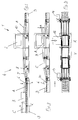
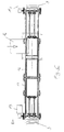
- the drawing comprises an arrangement for feeding and filling of containers A, B, C, D with articles or bulk goods in a filling station 1 with a filling funnel 2 on the input and output sides a known conveyor line 3, wherein containers A, B, C, D open at the top along a conveyor path 3, for example in the manner of an accumulation roller conveyor, using a stopper 30 can be stowed.
- the containers B, C according to FIG. 1 have a larger container height h 'than the container A, which is the small container height h owns.
- the containers A, B, C, D have on the top a covenant 6.
- the conveyor section 3 on the input side closes immediately before, in and after the filling station a fixed, not Height-adjustable container drive 4.
- the containers A, B, C, D are height-adjustable along the container drive 4 can be fed into the filling station 1 and are independent of the container height h, h 'in a given Distance a between the top of the container and the fixed one Bottom of the hopper in the filling position under the Hopper 2 positioned.
- the container drive 4 is composed of two arranged one behind the other rotating individual drives 11, 12 each with one Drive unit 13, 14 together in the form of electric motors, one single drive 11 the entrance area and the other Single drive 12 the filling area and the exit area is assigned to the filling station 1.
- the individual drives 11, 12 each consist of an inclined section S1 or S2 and a horizontal section H1 or H2, the horizontal sections H1, H2 of both individual drives 11, 12 facing each other.
- the rising inclined section S1 of the single drive 11 of the The entrance area is a sloping conveyor belt section 13 assigned on which the containers A, B, C, D up to one Bundle takeover by the ascending sloping section S1 support.
- the sloping inclined section S2 of the individual drive 12 of the The starting area is a rising conveyor belt section 14 assigned on which is by the sloping sloping section filled container A, B, C, D held on the collar 6 support and take over again at the bottom on a spout become.
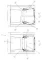
- a vibrating clamping device 15 a pneumatic drive cylinder provided, the one Executes shaking in the longitudinal or in the conveying direction, after a container C is clamped in the Filling position according to Figure 8 by drawing in from the side Pneumatic cylinders 31 from the position shown in Figure 7.
- Upper movable jaws 32 then clamp the collar 6 laterally of the container C together on both sides, the container approx. 3mm high.
- the geometry according to FIG. 8 is so far not shown in terms of construction.
- At least the container height h, h 'one on the conveyor line 3 arriving or in the container drive 4 container A, B, C, D is by the aforementioned recognition or. Identification device (barcode reading, transponder reading, Photocell, etc.) recognized.
- the hopper 2 has a flat short riser 16 for Fill the funnel 2 with articles or bulk goods.
- the container drive 4 is driven continuously.
- a Height-adjustable container drive 4 in the area of the filling station 1 be provided on which the container A, B, C, D on the bottom side are supported and / or guided laterally.
- the height-adjustable container drive 4 has at least one sloping, in the slope 7 adjustable entrance area, one horizontal, height-adjustable middle area and a sloping exit area adjustable in the sloping 8, the horizontal central area of the hopper 2 is assigned.
- This container drive 4 can, for example, be a single rotating one Conveyor belt or two lateral toothed belts with fixed space
- Have end rollers and the horizontal middle area have height and length adjustable pulleys 9. 10. This allows different heights of a horizontal one Middle range with constant toothed belt circumferential length to adjust. If the middle area is long, the height difference is low to the end rolls. If the middle section is short, the height difference is big.
- Bias binding can be completely dispensed with and only a horizontal (central) section can be provided, which, as well as a container on it, is facing down or clocked up or shifted in height to adjust the distance a when filling, and by filling the container back to the initial level, z. B. by using actuators and height control of photocells.
Landscapes
- Engineering & Computer Science (AREA)
- Mechanical Engineering (AREA)
- Basic Packing Technique (AREA)
- Container Filling Or Packaging Operations (AREA)
- Supply Of Fluid Materials To The Packaging Location (AREA)
Applications Claiming Priority (2)
| Application Number | Priority Date | Filing Date | Title |
|---|---|---|---|
| DE19859941A DE19859941A1 (de) | 1998-12-24 | 1998-12-24 | Verfahren und Anordnung zum Befüllen von Behältern mit Artikeln oder Schüttgut in einer Füllstation |
| DE19859941 | 1998-12-24 |
Publications (2)
| Publication Number | Publication Date |
|---|---|
| EP1013559A1 true EP1013559A1 (fr) | 2000-06-28 |
| EP1013559B1 EP1013559B1 (fr) | 2002-11-13 |
Family
ID=7892588
Family Applications (1)
| Application Number | Title | Priority Date | Filing Date |
|---|---|---|---|
| EP99125479A Expired - Lifetime EP1013559B1 (fr) | 1998-12-24 | 1999-12-21 | Procédé et dispositif pour remplir des récipients avec des articles ou des matières en vrac dans un poste de remplissage |
Country Status (4)
| Country | Link |
|---|---|
| EP (1) | EP1013559B1 (fr) |
| AT (1) | ATE227668T1 (fr) |
| DE (2) | DE19859941A1 (fr) |
| ES (1) | ES2186296T3 (fr) |
Cited By (1)
| Publication number | Priority date | Publication date | Assignee | Title |
|---|---|---|---|---|
| CN102700918A (zh) * | 2012-05-31 | 2012-10-03 | 天津博信汽车零部件有限公司 | 一种冲压内板件装箱系统 |
Citations (2)
| Publication number | Priority date | Publication date | Assignee | Title |
|---|---|---|---|---|
| CA1028668A (fr) * | 1975-12-30 | 1978-03-28 | Canadian Oxygen Limited | Systeme d'acheminement et de remplissage de contenants |
| EP0745535A1 (fr) * | 1995-06-02 | 1996-12-04 | P.E.E.M. FÖRDERANLAGEN Ges.m.b.H. | Dispositif de chargement de récipients |
-
1998
- 1998-12-24 DE DE19859941A patent/DE19859941A1/de not_active Ceased
-
1999
- 1999-12-21 DE DE59903389T patent/DE59903389D1/de not_active Expired - Lifetime
- 1999-12-21 EP EP99125479A patent/EP1013559B1/fr not_active Expired - Lifetime
- 1999-12-21 ES ES99125479T patent/ES2186296T3/es not_active Expired - Lifetime
- 1999-12-21 AT AT99125479T patent/ATE227668T1/de active
Patent Citations (2)
| Publication number | Priority date | Publication date | Assignee | Title |
|---|---|---|---|---|
| CA1028668A (fr) * | 1975-12-30 | 1978-03-28 | Canadian Oxygen Limited | Systeme d'acheminement et de remplissage de contenants |
| EP0745535A1 (fr) * | 1995-06-02 | 1996-12-04 | P.E.E.M. FÖRDERANLAGEN Ges.m.b.H. | Dispositif de chargement de récipients |
Cited By (2)
| Publication number | Priority date | Publication date | Assignee | Title |
|---|---|---|---|---|
| CN102700918A (zh) * | 2012-05-31 | 2012-10-03 | 天津博信汽车零部件有限公司 | 一种冲压内板件装箱系统 |
| CN102700918B (zh) * | 2012-05-31 | 2015-06-10 | 天津博信汽车零部件有限公司 | 一种冲压内板件装箱系统 |
Also Published As
| Publication number | Publication date |
|---|---|
| DE59903389D1 (de) | 2002-12-19 |
| DE19859941A1 (de) | 2000-07-06 |
| ATE227668T1 (de) | 2002-11-15 |
| ES2186296T3 (es) | 2003-05-01 |
| EP1013559B1 (fr) | 2002-11-13 |
Similar Documents
| Publication | Publication Date | Title |
|---|---|---|
| EP0583562B1 (fr) | Dispositif pour amener d'une manière continue des corps d'ouvrage | |
| EP0658499B1 (fr) | Chemin de convoyage télescopique pour transporter et mesurer des objets | |
| EP0623542B1 (fr) | Dispositif pour empiler un chant de feuilles imprimées | |
| DE60204026T2 (de) | Fördereinrichtung für verpackungen und verfahren zum abgeben einer verpackung | |
| DE3232039A1 (de) | Vorrichtung zum befoerdern von sortiertem, gestapeltem gut | |
| DE3616470A1 (de) | Verfahren und vorrichtung zum ablegen kontinuierlich zu einer stapelstelle gefoerderter bogen | |
| DE60113580T2 (de) | Schneidemaschine für eine Vielzahl von Küchen- und/oder Toiletten-Papierrollen | |
| DE2125991A1 (de) | Verfahren und Vorrichtung zum Transport gestapelter flacher Gegenstände in Aufeinanderfolge zu einem Auffangen | |
| EP0608861A2 (fr) | Procédé et dispositif pour alimenter des objets sensibles dans une machine de traitement | |
| DE19648173A1 (de) | Vorrichtung zum Fördern von Produkten wie Druckbogenstapel | |
| EP1350750B1 (fr) | Méthode et dispositif pour former des piles d'objets plats arrivant en continu | |
| EP1405809A1 (fr) | Dispositif pour former des colis de produits empilés | |
| EP1013559B1 (fr) | Procédé et dispositif pour remplir des récipients avec des articles ou des matières en vrac dans un poste de remplissage | |
| DE4402468A1 (de) | Maschine zum Ordnen von Textilhülsen für Spinnmaschinen | |
| DE19811635B4 (de) | Buchfertigungsfließstrecke | |
| DE4344114C2 (de) | Vorrichtung zum Einbringen von hintereinander gestapelten, flachen Produkten, insbesondere gefüllten Kuverts, in eine wannenförmige Box, insbesondere Postbox | |
| DE2755390C2 (de) | Verfahren und Vorrichtung zur gleichmäßigen Zuführung von Gegenständen zu einer Verarbeitungsmaschine | |
| AT394324B (de) | Verfahren und anlage zum entzundern von rundstahlstaeben | |
| EP1199275B1 (fr) | Dispositif pour la formation d'une pile de feuilles imprimées arrangées l' une à côté de l'autre | |
| DE4439970A1 (de) | Vorrichtung zum staubfreien Transport von Tabletten oder dergleichen in tiefe Behälter | |
| DE4010698C1 (fr) | ||
| DE602005000340T3 (de) | FIFO-Speicher mit variabler Kapazität, mit einer Auswurfstation | |
| DE2856295A1 (de) | Vorrichtung zum anlegen von flachen gegenstaenden wie kartons o.dgl. fuer maschinen zum bearbeiten solcher gegenstaende | |
| EP1943148B1 (fr) | Systeme pour remplir une ligne alveolee d'une matiere de remplissage | |
| EP1522509B1 (fr) | Appareil d'empilage de produits plats |
Legal Events
| Date | Code | Title | Description |
|---|---|---|---|
| PUAI | Public reference made under article 153(3) epc to a published international application that has entered the european phase |
Free format text: ORIGINAL CODE: 0009012 |
|
| AK | Designated contracting states |
Kind code of ref document: A1 Designated state(s): AT BE CH CY DE DK ES FI FR GB GR IE IT LI LU MC NL PT SE |
|
| AX | Request for extension of the european patent |
Free format text: AL;LT;LV;MK;RO;SI |
|
| 17P | Request for examination filed |
Effective date: 20001209 |
|
| AKX | Designation fees paid |
Free format text: AT BE CH CY DE DK ES FI FR GB GR IE IT LI LU MC NL PT SE |
|
| 17Q | First examination report despatched |
Effective date: 20010326 |
|
| GRAG | Despatch of communication of intention to grant |
Free format text: ORIGINAL CODE: EPIDOS AGRA |
|
| GRAG | Despatch of communication of intention to grant |
Free format text: ORIGINAL CODE: EPIDOS AGRA |
|
| GRAH | Despatch of communication of intention to grant a patent |
Free format text: ORIGINAL CODE: EPIDOS IGRA |
|
| GRAH | Despatch of communication of intention to grant a patent |
Free format text: ORIGINAL CODE: EPIDOS IGRA |
|
| GRAA | (expected) grant |
Free format text: ORIGINAL CODE: 0009210 |
|
| AK | Designated contracting states |
Kind code of ref document: B1 Designated state(s): AT BE CH CY DE DK ES FI FR GB GR IE IT LI LU MC NL PT SE |
|
| PG25 | Lapsed in a contracting state [announced via postgrant information from national office to epo] |
Ref country code: NL Free format text: LAPSE BECAUSE OF FAILURE TO SUBMIT A TRANSLATION OF THE DESCRIPTION OR TO PAY THE FEE WITHIN THE PRESCRIBED TIME-LIMIT Effective date: 20021113 Ref country code: IE Free format text: LAPSE BECAUSE OF FAILURE TO SUBMIT A TRANSLATION OF THE DESCRIPTION OR TO PAY THE FEE WITHIN THE PRESCRIBED TIME-LIMIT Effective date: 20021113 Ref country code: GR Free format text: LAPSE BECAUSE OF FAILURE TO SUBMIT A TRANSLATION OF THE DESCRIPTION OR TO PAY THE FEE WITHIN THE PRESCRIBED TIME-LIMIT Effective date: 20021113 Ref country code: FI Free format text: LAPSE BECAUSE OF FAILURE TO SUBMIT A TRANSLATION OF THE DESCRIPTION OR TO PAY THE FEE WITHIN THE PRESCRIBED TIME-LIMIT Effective date: 20021113 |
|
| REF | Corresponds to: |
Ref document number: 227668 Country of ref document: AT Date of ref document: 20021115 Kind code of ref document: T |
|
| REG | Reference to a national code |
Ref country code: GB Ref legal event code: FG4D Free format text: NOT ENGLISH |
|
| REG | Reference to a national code |
Ref country code: CH Ref legal event code: EP |
|
| REG | Reference to a national code |
Ref country code: IE Ref legal event code: FG4D Free format text: GERMAN |
|
| REF | Corresponds to: |
Ref document number: 59903389 Country of ref document: DE Date of ref document: 20021219 |
|
| PG25 | Lapsed in a contracting state [announced via postgrant information from national office to epo] |
Ref country code: LU Free format text: LAPSE BECAUSE OF NON-PAYMENT OF DUE FEES Effective date: 20021221 |
|
| PG25 | Lapsed in a contracting state [announced via postgrant information from national office to epo] |
Ref country code: CY Free format text: LAPSE BECAUSE OF FAILURE TO SUBMIT A TRANSLATION OF THE DESCRIPTION OR TO PAY THE FEE WITHIN THE PRESCRIBED TIME-LIMIT Effective date: 20021231 Ref country code: BE Free format text: LAPSE BECAUSE OF NON-PAYMENT OF DUE FEES Effective date: 20021231 |
|
| PG25 | Lapsed in a contracting state [announced via postgrant information from national office to epo] |
Ref country code: SE Free format text: LAPSE BECAUSE OF FAILURE TO SUBMIT A TRANSLATION OF THE DESCRIPTION OR TO PAY THE FEE WITHIN THE PRESCRIBED TIME-LIMIT Effective date: 20030213 Ref country code: PT Free format text: LAPSE BECAUSE OF FAILURE TO SUBMIT A TRANSLATION OF THE DESCRIPTION OR TO PAY THE FEE WITHIN THE PRESCRIBED TIME-LIMIT Effective date: 20030213 Ref country code: DK Free format text: LAPSE BECAUSE OF FAILURE TO SUBMIT A TRANSLATION OF THE DESCRIPTION OR TO PAY THE FEE WITHIN THE PRESCRIBED TIME-LIMIT Effective date: 20030213 |
|
| GBT | Gb: translation of ep patent filed (gb section 77(6)(a)/1977) |
Effective date: 20030227 |
|
| NLV1 | Nl: lapsed or annulled due to failure to fulfill the requirements of art. 29p and 29m of the patents act | ||
| REG | Reference to a national code |
Ref country code: ES Ref legal event code: FG2A Ref document number: 2186296 Country of ref document: ES Kind code of ref document: T3 |
|
| ET | Fr: translation filed | ||
| BERE | Be: lapsed |
Owner name: *KNAPP LOGISTIK AUTOMATION G.M.B.H. Effective date: 20021231 |
|
| PG25 | Lapsed in a contracting state [announced via postgrant information from national office to epo] |
Ref country code: MC Free format text: LAPSE BECAUSE OF NON-PAYMENT OF DUE FEES Effective date: 20030701 |
|
| REG | Reference to a national code |
Ref country code: IE Ref legal event code: FD4D Ref document number: 1013559E Country of ref document: IE |
|
| PLBE | No opposition filed within time limit |
Free format text: ORIGINAL CODE: 0009261 |
|
| STAA | Information on the status of an ep patent application or granted ep patent |
Free format text: STATUS: NO OPPOSITION FILED WITHIN TIME LIMIT |
|
| 26N | No opposition filed |
Effective date: 20030814 |
|
| PG25 | Lapsed in a contracting state [announced via postgrant information from national office to epo] |
Ref country code: LI Free format text: LAPSE BECAUSE OF NON-PAYMENT OF DUE FEES Effective date: 20031231 Ref country code: CH Free format text: LAPSE BECAUSE OF NON-PAYMENT OF DUE FEES Effective date: 20031231 |
|
| REG | Reference to a national code |
Ref country code: CH Ref legal event code: PL |
|
| REG | Reference to a national code |
Ref country code: FR Ref legal event code: PLFP Year of fee payment: 17 |
|
| REG | Reference to a national code |
Ref country code: FR Ref legal event code: PLFP Year of fee payment: 18 |
|
| REG | Reference to a national code |
Ref country code: FR Ref legal event code: PLFP Year of fee payment: 19 |
|
| REG | Reference to a national code |
Ref country code: DE Ref legal event code: R082 Ref document number: 59903389 Country of ref document: DE |
|
| REG | Reference to a national code |
Ref country code: FR Ref legal event code: PLFP Year of fee payment: 20 |
|
| PGFP | Annual fee paid to national office [announced via postgrant information from national office to epo] |
Ref country code: IT Payment date: 20180918 Year of fee payment: 20 |
|
| PGFP | Annual fee paid to national office [announced via postgrant information from national office to epo] |
Ref country code: DE Payment date: 20181022 Year of fee payment: 20 Ref country code: AT Payment date: 20181023 Year of fee payment: 20 |
|
| PGFP | Annual fee paid to national office [announced via postgrant information from national office to epo] |
Ref country code: FR Payment date: 20181024 Year of fee payment: 20 Ref country code: GB Payment date: 20181022 Year of fee payment: 20 |
|
| PGFP | Annual fee paid to national office [announced via postgrant information from national office to epo] |
Ref country code: ES Payment date: 20190104 Year of fee payment: 20 |
|
| REG | Reference to a national code |
Ref country code: DE Ref legal event code: R071 Ref document number: 59903389 Country of ref document: DE |
|
| REG | Reference to a national code |
Ref country code: GB Ref legal event code: PE20 Expiry date: 20191220 |
|
| PG25 | Lapsed in a contracting state [announced via postgrant information from national office to epo] |
Ref country code: GB Free format text: LAPSE BECAUSE OF EXPIRATION OF PROTECTION Effective date: 20191220 |
|
| REG | Reference to a national code |
Ref country code: AT Ref legal event code: MK07 Ref document number: 227668 Country of ref document: AT Kind code of ref document: T Effective date: 20191221 |
|
| REG | Reference to a national code |
Ref country code: ES Ref legal event code: FD2A Effective date: 20200721 |
|
| PG25 | Lapsed in a contracting state [announced via postgrant information from national office to epo] |
Ref country code: ES Free format text: LAPSE BECAUSE OF EXPIRATION OF PROTECTION Effective date: 20191222 |