EP1013574A1 - System zur Förderung unter Verwendung eines Linearmotors - Google Patents
System zur Förderung unter Verwendung eines Linearmotors Download PDFInfo
- Publication number
- EP1013574A1 EP1013574A1 EP99116448A EP99116448A EP1013574A1 EP 1013574 A1 EP1013574 A1 EP 1013574A1 EP 99116448 A EP99116448 A EP 99116448A EP 99116448 A EP99116448 A EP 99116448A EP 1013574 A1 EP1013574 A1 EP 1013574A1
- Authority
- EP
- European Patent Office
- Prior art keywords
- moving assembly
- linear motor
- conveying system
- sending
- receiving
- Prior art date
- Legal status (The legal status is an assumption and is not a legal conclusion. Google has not performed a legal analysis and makes no representation as to the accuracy of the status listed.)
- Granted
Links
- 239000000428 dust Substances 0.000 abstract description 5
- 238000010586 diagram Methods 0.000 description 5
- 230000001133 acceleration Effects 0.000 description 4
- 238000013461 design Methods 0.000 description 3
- 230000006698 induction Effects 0.000 description 3
- 230000015654 memory Effects 0.000 description 3
- 238000012423 maintenance Methods 0.000 description 1
- 238000005259 measurement Methods 0.000 description 1
- 238000000034 method Methods 0.000 description 1
- 238000011022 operating instruction Methods 0.000 description 1
- 230000008672 reprogramming Effects 0.000 description 1
- 230000004044 response Effects 0.000 description 1
- 238000012546 transfer Methods 0.000 description 1
- 239000002699 waste material Substances 0.000 description 1
Images


Classifications
-
- B—PERFORMING OPERATIONS; TRANSPORTING
- B65—CONVEYING; PACKING; STORING; HANDLING THIN OR FILAMENTARY MATERIAL
- B65G—TRANSPORT OR STORAGE DEVICES, e.g. CONVEYORS FOR LOADING OR TIPPING, SHOP CONVEYOR SYSTEMS OR PNEUMATIC TUBE CONVEYORS
- B65G54/00—Non-mechanical conveyors not otherwise provided for
- B65G54/02—Non-mechanical conveyors not otherwise provided for electrostatic, electric, or magnetic
Definitions
- the present invention relates to a conveying system that uses a linear motor for conveying works, assembly components, or other articles to be conveyed.
- Conveying apparatuses have been extensively used that employ rollers or belts to carry works, assembly components, or other articles to be conveyed. Especially in the case of a conveying apparatus that employs a belt, in order to stop only a particular article in transfer at a predetermined position, the article has to be forcibly restrained, inevitably producing friction between the belt and the article. Further, the accuracy of positioning at the stop point is not very high.
- linear motor type conveying systems have been proposed and used as the conveying systems for clean rooms, nuclear power stations, physical distribution, etc.
- a linear induction motor is capable of carrying considerably heavy articles and it is therefore being used as a typical motor used for conveyance.
- the linear induction motors are considered unsuited for applications that require accurate positioning at stop points.
- the conventional conveying systems employing belts or rollers have difficulties in the aspect of the control of dust, carrying speed, maintenance, service life, and positioning control.
- the linear induction motor type is also disadvantageous in positioning control.
- the linear motors that allow the braking characteristics thereof to be adjusted have been requiring power be fed to a moving unit thereof, so that the moving unit is likely to produce dust.
- a conveying system using a linear motor comprising a passive moving assembly of a linear motor, which is loaded with an article to be conveyed, a scale provided on the moving assembly, a rail for guiding the moving assembly, a sending drive coil disposed at a sending station associated with the rail, a receiving drive coil disposed at a receiving station associated with the rail, which is positioned away from the sending station, a contactless sensor which is disposed at least at the receiving station and which detects the scale, drivers for driving the sending and receiving drive coils, and control means to which information regarding the moving assembly from the sensor is connected, and which drives the respective drivers to accelerate and send the moving assembly, then to stop at a predetermined position at the receiving station following non-energization travel.
- the moving assembly has a permanent magnet, and said linear motor can be a linear DC motor.
- a combination of the scale and the contactless sensor may be a combination of a linear scale and a photoelectric sensor, or a combination of a magnetic scale and a magnetic sensor or other positioning sensor.
- the control means is configured to cause the driver to send the moving assembly at a predetermined sending speed that matches a load of the moving assembly and the length of a non-energized travel passage.
- the control means reads the linear scale by the sensor after the moving assembly is received at the receiving station to detect the speed of the moving assembly, compares the detected speed with a reference receiving speed, and corrects the speed of the moving assembly so as to position and stop the moving assembly at a predetermined position.
- the sending station and the receiving station are provided with the same capability and can be interchangeably operated under the control by the control means.
- a plurality of the sending and receiving drive coils are disposed to construct an assembly line.
- the moving assembly can be intermittently moved for positioning after the moving assembly is received and stopped at the receiving station.
- the moving assembly is returned from the receiving station to the sending station.
- Figure 1 is a block diagram showing an embodiment of a conveying system in accordance with the present invention and a graph for explaining the operation thereof;
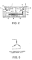
- Fig. 2 is a side sectional view (a sectional view observed orthogonally in relation to a transit direction) showing the configuration of an embodiment of a linear motor used with the system in accordance with the present invention;
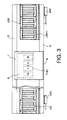
- Fig. 3 is a top plan view of the linear motor;
- Fig. 4 is a front view of the linear motor;
- Fig. 5 is a connection circuit diagram of a drive coil of the linear motor.
- a truck 1 loaded with articles to be conveyed (hereinafter referred to as "works") is provided on a passive moving assembly of a linear DC motor, and a linear scale 9 is provided on the moving assembly.
- the moving assembly is provided with a yoke 6 and permanent magnets 7 and 8 via a prop 1a, the permanent magnets 7 and 8 being positioned to sandwich a drive coil 13 with gaps maintained therebetween at a station to be discussed hereinafter.
- the moving assembly is able to move by the guidance of rails 11 and 12 (see Figs. 2 and 3) via ball bearings 2, 3, 4, and 5.
- the ball bearings 2 and 5 roll in contact with the top surfaces of the rails 11 and 12, while the ball bearings 3 and 4 roll in contact with the inner surfaces of the rails 11 and 12.
- the rails 11 and 12 are fixed to an enclosure 10.
- a sending drive coil 13S is disposed at a sending station S
- a receiving drive coil 13R is disposed at a receiving station R located at a position away from the sending station S by a predetermined distance.
- Each station has contactless sensors for detecting the linear scale of the moving assembly.
- a photoelectric detector having a light emitting element and a light receiving element inserted in sensor heads 14S and 14R are used in the embodiment.
- the contactless sensors have to be disposed only at the receiving station R.
- the combination of the scale and the contactless sensor may be alternatively replaced by the combination of a magnetic scale and a magnetic sensor. In other words, it is important that the contactless design prevents generation of dust.
- the sending and receiving drive coils 13S and 13R are driven by servo drivers 20 and 21, respectively. Connected to the respective servo drivers 20 and 21 is the information regarding the moving assembly received from the sensor heads 14S and 14R. It is possible to configure the system so that the information regarding the moving assembly received from the sensor heads 14S and 14R is transmitted to a CPU 22 to process the information and feed it back in the form of a control signal to the servo drivers 20 and 21.
- Control signal generating devices incorporated in the CPU 22 or the servo drivers 20 and 21 drive the drivers 20 and 21 to accelerate and carry out the moving assembly, and stop it at a predetermined position of the receiving station.
- a transit track is provided with a portion wherein the truck travels with no energization because providing the whole transit track with coils would waste electric power, considering the dimensional relationship between the coils and moving magnets over the distance from the sending coil 13S to the receiving coil 13R.
- FIG. 5 is the connection diagram of one three-phase coil.
- the drivers 20 and 21 are of the intelligent three-phase servo type.
- a motion program including the setting, acceleration, deceleration, speed, travel distance, various gains, etc. of the motor and the linear scale necessary for the servo operation is stored in the memories of the drivers.
- the CPU 22 and the drivers are connected via, for example, a serial interface (RS-232C) to transmit a minimum of instructions including start, stop, etc.
- RS-232C serial interface
- the moving assembly corresponds to the coil portion of the sending station S, while the linear scale 9 corresponds to the sensor head 14S.
- the driver (DRS) 20 is in a servo-ON state and ready for operation in response to an instruction received from the CPU.
- the driver (DRS) 20 accelerates as shown by the acceleration zone of Fig. 1 according to an operation pattern stored in the memory beforehand.
- the driver (DRS) 20 is set such that it is switched to a servo-OFF state at the moment the sensor head 14S can no longer read a signal from the scale 9 as the truck of the moving assembly travels. Then, the truck of the moving assembly travels by itself along the rails with no energization, which is referred to as "non-energization travel zone".
- the driver (DDR) 21 is switched to the servo-ON state at the moment the receiving sensor head 14R detects the scale 9 on the truck when the truck of the moving assembly reaches. Under this condition, a signal from the scale 9 is read.
- a linear scale having a resolution of 1 to 10 ⁇ m is used, and the sending travel speed is set to 0.5 meter per second, and the receiving speed is set to 0.3 meter per second.
- the measurement time ranges from 0.5 ms to 5 ms (the travel distance over the time ranges from 5 to 100 ⁇ m). Correcting the set receiving speed to increase immediately following the calculation allows smooth receiving of the truck with no abrupt change in speed.
- the servo control mode is engaged and positioning at a preprogrammed point is performed.
- the positioning point can be arbitrarily set by programming.
- the moving assembly travels from the left to the right as illustrated in Fig. 1; the travel direction, however, can be reversed by modifying the control program.
- the acceleration, the travel speed, and positioning can be changed by reprogramming to change the non-energization travel distance.
- the conveying system employing the linear motor in accordance with the present invention enables an assembly line to be constructed by disposing a plurality of sending and receiving drive coils described above.
- the moving assembly can be intermittently moved for further positioning.
- the moving assembly can also be returned to the sending station from the receiving station.
- the relationship between the number of sets of coils and of magnets and the length of a linear scale depends on the design and cost of the unit.
- This embodiment uses four sets of magnets, and three or four sets of three-phase coils for both sending and receiving coils; obviously, however, other configurations are also possible.
- the drivers are the intelligent three-phase servo type, and the motion program including the setting, acceleration, deceleration, speed, travel distance, various gains, etc. of the motor and the linear scale necessary for the servo operation is stored in the memories of the drivers. These parameters can be integrally controlled using a control device.
- the present invention permits easy control of positioning at a desired point, which has been difficult in conventional conveying systems.
- a sudden change in speed can be inhibited to permit smooth operation by measuring the speed of the truck at a point when the truck reaches a receiving zone after it is sent out and travels through the self-propelling zone so as to correct a preset speed on the receiving side for achieving synchronization.
- the use of the conveying system that employs the linear motor in accordance with the present invention makes it possible to construct an assembly line.
Landscapes
- Non-Mechanical Conveyors (AREA)
- Control Of Linear Motors (AREA)
- Control Of Vehicles With Linear Motors And Vehicles That Are Magnetically Levitated (AREA)
Applications Claiming Priority (2)
| Application Number | Priority Date | Filing Date | Title |
|---|---|---|---|
| JP10376691A JP2000191140A (ja) | 1998-12-26 | 1998-12-26 | リニアモ―タを用いた搬送システム |
| JP37669198 | 1998-12-26 |
Publications (2)
| Publication Number | Publication Date |
|---|---|
| EP1013574A1 true EP1013574A1 (de) | 2000-06-28 |
| EP1013574B1 EP1013574B1 (de) | 2004-09-08 |
Family
ID=18507567
Family Applications (1)
| Application Number | Title | Priority Date | Filing Date |
|---|---|---|---|
| EP99116448A Expired - Lifetime EP1013574B1 (de) | 1998-12-26 | 1999-08-21 | System zur Förderung unter Verwendung eines Linearmotors |
Country Status (4)
| Country | Link |
|---|---|
| US (1) | US6283039B1 (de) |
| EP (1) | EP1013574B1 (de) |
| JP (1) | JP2000191140A (de) |
| DE (1) | DE69919966T2 (de) |
Cited By (5)
| Publication number | Priority date | Publication date | Assignee | Title |
|---|---|---|---|---|
| DE102004027905A1 (de) * | 2004-06-09 | 2005-12-29 | Leybold Optics Gmbh | Vorrichtung zum Transport von Substraten |
| EP2088026A3 (de) * | 2008-02-06 | 2014-07-02 | Murata Machinery, Ltd. | Bewegliches System mit Linearmotor |
| WO2019129155A1 (zh) * | 2017-12-27 | 2019-07-04 | 北京动仿航泰科技有限公司 | 矩阵式轨道系统、关联回路式生产线及其生产方法 |
| CN111829624A (zh) * | 2019-04-15 | 2020-10-27 | 北京万集科技股份有限公司 | 汽车衡系统 |
| WO2021097806A1 (en) * | 2019-11-22 | 2021-05-27 | Abb Schweiz Ag | Conveyor, conveying system and manufacturing method of conveyor |
Families Citing this family (9)
| Publication number | Priority date | Publication date | Assignee | Title |
|---|---|---|---|---|
| IT1309303B1 (it) * | 1999-06-30 | 2002-01-22 | Gd Spa | Macchina impacchettarice di sigarette. |
| DE102007025822A1 (de) * | 2007-06-02 | 2008-12-18 | Lars Bergmann | Kombinierbares Flächenelement mit einer Vielzahl von ansteuerbaren Wandlerelementen |
| US8084969B2 (en) * | 2007-10-01 | 2011-12-27 | Allegro Microsystems, Inc. | Hall-effect based linear motor controller |
| EP3029723B1 (de) * | 2014-12-05 | 2020-09-16 | Robert Bosch GmbH | Transportvorrichtung und Transportverfahren zum Transport eines zerbrechlichen Gegenstandes |
| US11539244B2 (en) * | 2017-09-28 | 2022-12-27 | Rockwell Automation Technologies, Inc. | Method and apparatus for data transmission over an inductive link for an independent cart system |
| US10654660B2 (en) * | 2018-01-31 | 2020-05-19 | Laitram, L.L.C. | Hygienic magnetic tray and conveyor |
| CN113395032B (zh) * | 2021-08-18 | 2021-11-16 | 南通电博士自动化设备有限公司 | 基于云计算的直线电机高效运行的控制方法及系统 |
| BR102021018108A2 (pt) | 2021-09-13 | 2023-03-28 | Freed Participaçoes S/A | Esteira transportadora tracionada por motor de indução linear com primário de dupla face e secundário longo seccionado |
| CN119233936B (zh) * | 2022-11-11 | 2025-08-22 | 三菱电机株式会社 | 输送系统 |
Citations (2)
| Publication number | Priority date | Publication date | Assignee | Title |
|---|---|---|---|---|
| EP0400663A1 (de) * | 1989-06-01 | 1990-12-05 | Mazda Motor Corporation | Förderer mit Linearmotor |
| US5251741A (en) * | 1991-06-28 | 1993-10-12 | Kabushiki Kaisha Toshiba | Carrying apparatus having carrier levitated by magnetic force |
Family Cites Families (13)
| Publication number | Priority date | Publication date | Assignee | Title |
|---|---|---|---|---|
| JPS60187204A (ja) * | 1984-03-06 | 1985-09-24 | Fujitsu Ltd | リニアモ−タカ−の制御システム |
| JPS60204202A (ja) * | 1984-03-26 | 1985-10-15 | Toshiba Corp | 被搬送体の制御装置 |
| JPH0810993B2 (ja) * | 1984-03-28 | 1996-01-31 | 日立機電工業株式会社 | リニアモータによる移動体の停止制御方法及びその装置 |
| JPS6115557A (ja) * | 1984-06-30 | 1986-01-23 | Toshiba Corp | 浮上式搬送装置 |
| JPH088723B2 (ja) * | 1985-11-02 | 1996-01-29 | 日立機電工業株式会社 | リニアモ−タを用いた搬送装置 |
| JP2544122B2 (ja) * | 1986-11-29 | 1996-10-16 | 株式会社ダイフク | リニアモ−タ利用の搬送設備の停止制御装置 |
| US4718621A (en) * | 1986-10-24 | 1988-01-12 | Shinko Electric Co., Ltd. | Automatic transportation system |
| JPH0667048B2 (ja) * | 1988-06-02 | 1994-08-24 | 神鋼電機株式会社 | 搬送装置 |
| JP2559854B2 (ja) * | 1989-06-28 | 1996-12-04 | マツダ株式会社 | リニアモータを用いた搬送装置 |
| JPH03102007A (ja) * | 1989-09-14 | 1991-04-26 | Hitachi Kiden Kogyo Ltd | リニア搬送台車の位置決め装置 |
| JPH06100164A (ja) * | 1992-08-27 | 1994-04-12 | Hitachi Ltd | 磁気的に結合された搬送装置 |
| JPH0748028A (ja) * | 1993-08-06 | 1995-02-21 | Daifuku Co Ltd | 直流リニアモータ利用の移動設備 |
| DE19622699A1 (de) * | 1996-06-05 | 1997-12-11 | Krauss Maffei Ag | Regeleinrichtung und -verfahren für Motoren |
-
1998
- 1998-12-26 JP JP10376691A patent/JP2000191140A/ja active Pending
-
1999
- 1999-07-23 US US09/359,116 patent/US6283039B1/en not_active Expired - Fee Related
- 1999-08-21 DE DE69919966T patent/DE69919966T2/de not_active Expired - Fee Related
- 1999-08-21 EP EP99116448A patent/EP1013574B1/de not_active Expired - Lifetime
Patent Citations (2)
| Publication number | Priority date | Publication date | Assignee | Title |
|---|---|---|---|---|
| EP0400663A1 (de) * | 1989-06-01 | 1990-12-05 | Mazda Motor Corporation | Förderer mit Linearmotor |
| US5251741A (en) * | 1991-06-28 | 1993-10-12 | Kabushiki Kaisha Toshiba | Carrying apparatus having carrier levitated by magnetic force |
Cited By (8)
| Publication number | Priority date | Publication date | Assignee | Title |
|---|---|---|---|---|
| DE102004027905A1 (de) * | 2004-06-09 | 2005-12-29 | Leybold Optics Gmbh | Vorrichtung zum Transport von Substraten |
| EP2088026A3 (de) * | 2008-02-06 | 2014-07-02 | Murata Machinery, Ltd. | Bewegliches System mit Linearmotor |
| WO2019129155A1 (zh) * | 2017-12-27 | 2019-07-04 | 北京动仿航泰科技有限公司 | 矩阵式轨道系统、关联回路式生产线及其生产方法 |
| US11618483B2 (en) | 2017-12-27 | 2023-04-04 | Dofsim Technologies Co., Ltd. | Matrix track structure and system, production line with associated loops and production method using the production line |
| CN111829624A (zh) * | 2019-04-15 | 2020-10-27 | 北京万集科技股份有限公司 | 汽车衡系统 |
| WO2021097806A1 (en) * | 2019-11-22 | 2021-05-27 | Abb Schweiz Ag | Conveyor, conveying system and manufacturing method of conveyor |
| CN114616198A (zh) * | 2019-11-22 | 2022-06-10 | Abb瑞士股份有限公司 | 输送机、输送系统以及输送机的制造方法 |
| US11780688B2 (en) | 2019-11-22 | 2023-10-10 | Abb Schweiz Ag | Conveyor, conveying system and manufacturing method of conveyor |
Also Published As
| Publication number | Publication date |
|---|---|
| US6283039B1 (en) | 2001-09-04 |
| DE69919966T2 (de) | 2005-11-17 |
| JP2000191140A (ja) | 2000-07-11 |
| EP1013574B1 (de) | 2004-09-08 |
| DE69919966D1 (de) | 2004-10-14 |
Similar Documents
| Publication | Publication Date | Title |
|---|---|---|
| EP1013574B1 (de) | System zur Förderung unter Verwendung eines Linearmotors | |
| US10442637B2 (en) | Linear drive system having central, distributed and group control | |
| US10717365B2 (en) | System and method for limiting motion in an independent cart system | |
| US10300793B2 (en) | System and method for providing power to a moving element | |
| EP2691319B1 (de) | Positionseinstellsystem für paletten | |
| US4855656A (en) | Driverless car travelling guide system | |
| EP2747257A2 (de) | Gesteuertes Bewegungssystem | |
| CA2495131C (en) | A precise transport posiitoning apparatus using a closed loop controlled, non-direct drive or friction drive system with absolute positioning encoder | |
| KR102552246B1 (ko) | 리니어모터반송시스템 및 그 운용방법 | |
| JP3235708B2 (ja) | リニアモータ利用の搬送設備 | |
| JP2553043B2 (ja) | 浮上式搬送装置 | |
| JPH0687603B2 (ja) | 浮上式搬送装置 | |
| JP3280414B2 (ja) | 搬送装置 | |
| JP7673579B2 (ja) | 搬送システム | |
| JPH0818193B2 (ja) | ワーク搬送装置 | |
| KR102469777B1 (ko) | 하이브리드 lms 시스템 | |
| JP3363180B2 (ja) | 搬送装置 | |
| US20250100816A1 (en) | Method and electromagnetic transport device for detecting a mover | |
| JP2005086858A (ja) | 搬送用磁石可動型リニアモータ | |
| JPS62166707A (ja) | リニアモ−タ利用の磁気浮上式搬送設備 | |
| JPH0630524B2 (ja) | 搬送装置用移動体の走行制御装置 | |
| JPS5911767A (ja) | 搬送装置 | |
| JPS63167603A (ja) | 搬送装置の制御装置 | |
| JP2000184513A (ja) | リニア式カプセル型走行装置および走行不能復旧方法 | |
| JPS61135303A (ja) | リニアモ−タ搬送装置の制御方法 |
Legal Events
| Date | Code | Title | Description |
|---|---|---|---|
| PUAI | Public reference made under article 153(3) epc to a published international application that has entered the european phase |
Free format text: ORIGINAL CODE: 0009012 |
|
| AK | Designated contracting states |
Kind code of ref document: A1 Designated state(s): DE GB |
|
| AX | Request for extension of the european patent |
Free format text: AL;LT;LV;MK;RO;SI |
|
| 17P | Request for examination filed |
Effective date: 20001205 |
|
| AKX | Designation fees paid |
Free format text: DE GB |
|
| 17Q | First examination report despatched |
Effective date: 20020227 |
|
| GRAP | Despatch of communication of intention to grant a patent |
Free format text: ORIGINAL CODE: EPIDOSNIGR1 |
|
| GRAS | Grant fee paid |
Free format text: ORIGINAL CODE: EPIDOSNIGR3 |
|
| GRAA | (expected) grant |
Free format text: ORIGINAL CODE: 0009210 |
|
| AK | Designated contracting states |
Kind code of ref document: B1 Designated state(s): DE GB |
|
| REG | Reference to a national code |
Ref country code: GB Ref legal event code: FG4D |
|
| REF | Corresponds to: |
Ref document number: 69919966 Country of ref document: DE Date of ref document: 20041014 Kind code of ref document: P |
|
| PLBE | No opposition filed within time limit |
Free format text: ORIGINAL CODE: 0009261 |
|
| STAA | Information on the status of an ep patent application or granted ep patent |
Free format text: STATUS: NO OPPOSITION FILED WITHIN TIME LIMIT |
|
| 26N | No opposition filed |
Effective date: 20050609 |
|
| PGFP | Annual fee paid to national office [announced via postgrant information from national office to epo] |
Ref country code: DE Payment date: 20080905 Year of fee payment: 10 |
|
| PGFP | Annual fee paid to national office [announced via postgrant information from national office to epo] |
Ref country code: GB Payment date: 20080903 Year of fee payment: 10 |
|
| GBPC | Gb: european patent ceased through non-payment of renewal fee |
Effective date: 20090821 |
|
| PG25 | Lapsed in a contracting state [announced via postgrant information from national office to epo] |
Ref country code: DE Free format text: LAPSE BECAUSE OF NON-PAYMENT OF DUE FEES Effective date: 20100302 |
|
| PG25 | Lapsed in a contracting state [announced via postgrant information from national office to epo] |
Ref country code: GB Free format text: LAPSE BECAUSE OF NON-PAYMENT OF DUE FEES Effective date: 20090821 |