EP1013587A2 - Appareil de transport de feuilles - Google Patents
Appareil de transport de feuilles Download PDFInfo
- Publication number
- EP1013587A2 EP1013587A2 EP99310409A EP99310409A EP1013587A2 EP 1013587 A2 EP1013587 A2 EP 1013587A2 EP 99310409 A EP99310409 A EP 99310409A EP 99310409 A EP99310409 A EP 99310409A EP 1013587 A2 EP1013587 A2 EP 1013587A2
- Authority
- EP
- European Patent Office
- Prior art keywords
- sheet
- conveying
- center line
- conveyance
- pair
- Prior art date
- Legal status (The legal status is an assumption and is not a legal conclusion. Google has not performed a legal analysis and makes no representation as to the accuracy of the status listed.)
- Granted
Links
Images


Classifications
-
- B—PERFORMING OPERATIONS; TRANSPORTING
- B65—CONVEYING; PACKING; STORING; HANDLING THIN OR FILAMENTARY MATERIAL
- B65H—HANDLING THIN OR FILAMENTARY MATERIAL, e.g. SHEETS, WEBS, CABLES
- B65H29/00—Delivering or advancing articles from machines; Advancing articles to or into piles
- B65H29/16—Delivering or advancing articles from machines; Advancing articles to or into piles by contact of one face only with moving tapes, bands, or chains
-
- B—PERFORMING OPERATIONS; TRANSPORTING
- B65—CONVEYING; PACKING; STORING; HANDLING THIN OR FILAMENTARY MATERIAL
- B65H—HANDLING THIN OR FILAMENTARY MATERIAL, e.g. SHEETS, WEBS, CABLES
- B65H29/00—Delivering or advancing articles from machines; Advancing articles to or into piles
- B65H29/52—Stationary guides or smoothers
-
- B—PERFORMING OPERATIONS; TRANSPORTING
- B65—CONVEYING; PACKING; STORING; HANDLING THIN OR FILAMENTARY MATERIAL
- B65H—HANDLING THIN OR FILAMENTARY MATERIAL, e.g. SHEETS, WEBS, CABLES
- B65H2301/00—Handling processes for sheets or webs
- B65H2301/30—Orientation, displacement, position of the handled material
- B65H2301/33—Modifying, selecting, changing orientation
- B65H2301/331—Skewing, correcting skew, i.e. changing slightly orientation of material
-
- B—PERFORMING OPERATIONS; TRANSPORTING
- B65—CONVEYING; PACKING; STORING; HANDLING THIN OR FILAMENTARY MATERIAL
- B65H—HANDLING THIN OR FILAMENTARY MATERIAL, e.g. SHEETS, WEBS, CABLES
- B65H2301/00—Handling processes for sheets or webs
- B65H2301/30—Orientation, displacement, position of the handled material
- B65H2301/36—Positioning; Changing position
- B65H2301/361—Positioning; Changing position during displacement
- B65H2301/3611—Positioning; Changing position during displacement centering, positioning material symmetrically relatively to a given axis of displacement
-
- B—PERFORMING OPERATIONS; TRANSPORTING
- B65—CONVEYING; PACKING; STORING; HANDLING THIN OR FILAMENTARY MATERIAL
- B65H—HANDLING THIN OR FILAMENTARY MATERIAL, e.g. SHEETS, WEBS, CABLES
- B65H2401/00—Materials used for the handling apparatus or parts thereof; Properties thereof
- B65H2401/10—Materials
-
- B—PERFORMING OPERATIONS; TRANSPORTING
- B65—CONVEYING; PACKING; STORING; HANDLING THIN OR FILAMENTARY MATERIAL
- B65H—HANDLING THIN OR FILAMENTARY MATERIAL, e.g. SHEETS, WEBS, CABLES
- B65H2511/00—Dimensions; Position; Numbers; Identification; Occurrences
- B65H2511/20—Location in space
- B65H2511/21—Angle
- B65H2511/216—Orientation, e.g. with respect to direction of movement
Definitions
- the present invention relates to sheet conveying apparatuses, and more particularly to a sheet conveying apparatus capable of conveying a rectangular sheet in such a manner that a center line of the sheet relative to conveyance direction of the sheet coincides with a predetermined center line for conveyance.
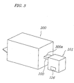
- an outlet 300a of a printing machine 300 is connected to an inlet of a sheet discharging apparatus 101 through a sheet conveying apparatus 100.
- the sheet conveying apparatus 100 has plural endless belts driven by a conveying motor.
- a post card as a sheet is printed by the printing machine 300, and conveyed by the sheet conveying apparatus 100, and then received in the sheet discharging apparatus 101.
- Ink on the post card as received is dried while the card is supported and conveyed in the sheet discharging apparatus 101. Then, the post card is dropped onto a tray 116 situated in a lower part of the sheet discharging apparatus 101, and stored therein.
- the sheet conveying apparatus 100 includes a conveying surface 102 for conveying a sheet.
- an opening 103 is formed along a conveying direction. That is, two sheet guiding plates are situated along a direction perpendicular to the conveying direction at a predetermined distance away from each other, thereby forming the conveying surface 102. The distance between the two sheet guiding plates can be optionally adjusted.
- sheet conveying means is situated in the opening 103.
- the sheet conveying means 103 includes a pair of pulleys 104 and three belts connecting the pulleys.
- the belts are parallel to each other. Upper surfaces of the belts contacting a bottom surface of the sheet 106 coincides with the conveying surface 102.
- the belts 105 convey the sheet 106 with the upper surfaces thereof contacting the bottom surface of the sheet 106.
- the sheet discharging apparatus 110 has, as a main body, a frame 110 approximately in a form of a box. On an upper portion of the frame 110, two shafts 111 are situated along two side edges of the sheet to be conveyed, respectively. Each shaft 111 has supporting means 112 comprising four plates.
- a pair of upper and lower driving axes 113 is situated below each of the shafts 111.
- the driving axes 113, 113 of the same pair are connected by two belts 114.
- Each of the belts 114 has many receiving flaps 115 formed at a predetermined distance therebetween. As illustrated in FIG. 6, in a view perpendicular to the conveying direction, a distance between the right and the left belts 114, 114 is relatively wide in an upper portion and approximately coincides with a width of the sheet 106 in a lower portion.
- a discharging tray 116 is drawably situated at the bottom of the frame 110.
- the sheet 106 after being printed thereon by a not-shown printing machine, is discharged to the outside of the machine.
- the printed sheet 106 discharged from the printing machine is placed on the conveying surface 102 of the sheet conveying apparatus 100.
- the belt 105 moves while contacting the bottom surface of the sheet 106, thereby moving the sheet 106 along the conveying surface 102.
- the sheet is positioned while being guided by the sheet guiding plates at both side edges thereof, and conveyed to the sheet discharging apparatus 101.
- the sheet 106 is supported by the pair of the supporting means 112 of the sheet discharging apparatus 101.
- the shaft 111 Upon rotation of the shaft 111, the sheet is downwardly conveyed and held by the receiving flaps 115 therebetween.
- Moving belts 114 convey the sheet downwardly. Ink printed on the sheet is dried during conveyance, and then the sheet is dropped onto the discharging tray 116 to be stacked therein.
- a center line L1 of the rectangular sheet 106 as discharged from the printing machine is parallel to the conveying direction, but this is not necessarily coincide with a center line L2 of the sheet conveying apparatus 100 for conveyance.
- the center line L1 of the sheet 106 in the conveyance direction is to coincide with the center line L2 for conveyance while the sheet 106 is conveyed to pass through the distance.
- the distance between the sheet guiding plates is adjustable according to the width of the sheet 106; therefore, it is inevitable that irregularity may occur in positioning the sheet guiding plates due to such adjustability.
- the distance between the sheet guiding plates must be adjusted fairly broader than the width of the sheet to allow the sheet to pass through the distance.
- the distance between the sheet guiding plates is adjusted broader than the width of the sheet to be guided, and the distance actually adjusted may include irregularity.
- the sheet 106 is fed into the sheet discharging apparatus 101 in such a manner that the center line L1 does not coincide with the center line L2.
- two side edges of the sheet 106 are not positioned equally to the pair of the supporting means 112, respectively. That is, in FIG. 7, the right side edge of the sheet 106 insufficiently engages the right supporting means, but the left side edge of the sheet 106 sufficiently engages the left supporting means. Therefore, when the supporting means 112 rotate in the direction shown by arrows in the drawing, as illustrated in FIG. 8, the right side edge of the sheet 106 leaves the supporting means 112, thereby falling onto the receiving flap 115. Then, the left side edge of the sheet 106 engages the left supporting means 112. Accordingly, the sheet 106 inclines relative to the pair of the belts 114, 114, so that the sheet can not be appropriately passed from the supporting means to the belts.
- An object of the present invention is to provide a sheet conveying apparatus capable of conveying the rectangular sheet in such a manner that the center line of the sheet coincides with a center line thereof for conveyance.
- a sheet conveying apparatus for conveying a rectangular sheet comprises conveying means for conveying the sheet while contacting a bottom surface of the sheet on a conveyance surface, and a pair of elastic members disposed on two sides of the conveying means, the elastic members guiding the sheet while contacting respective side edge of the sheet when the sheet is conveyed by the conveying means so that a center line of the sheet coincides with a center line for conveyance.
- a sheet conveying apparatus for conveying a rectangular sheet comprises conveying means for conveying the sheet while contacting a bottom surface of the sheet on a conveyance surface; a pair of guiding members disposed on two sides of the conveying means relative to a center line for conveyance, the guiding members being spaced apart from each other at a distance larger than a width of the sheet; and a pair of elastic members attached to the pair of guiding members respectively, each elastic member guiding the sheet conveyed between the pair of guiding members while contacting respective side edge of the sheet when the sheet is conveyed by the conveying means so that a center line of the sheet coincides with the center line for conveyance.
- the pair of guiding members are arranged so that the distance decreases in a conveying direction of the sheet, each elastic member is attached to respective downstream side of the each guiding member in the conveying direction of the sheet.
- the elastic member is a thin plate made of synthetic resin.
- the conveying means comprises a pair of rollers, each roller having a rotating axis perpendicular to the center line for conveyance and located along the center line for conveyance; and at least one pair of belts connecting the pair of rollers respectively, the belts being arranged symmetrically about the center line for conveyance so that a distance thereof decreases in the conveying direction of the sheet.
- the conveying means further comprises a center belt connecting the pair of rollers, and the center belt coincides with the center line for conveyance.
- FIGS. 1 and 2 A preferred embodiment of the present invention will be explained referring to FIGS. 1 and 2.
- the sheet conveying apparatus 1 of the embodiment is situated between the printing machine 300 and the sheet discharging apparatus 101.
- the sheet conveying apparatus 1 is used to convey a printed rectangular sheet 2 as discharged from the printing machine 300 into the sheet discharging apparatus 101.
- an upper surface of a main body 3 of the apparatus is designated as a conveying surface 4 for conveying a rectangular printing sheet 2.
- a center line L2 for conveying the sheet 2 is supposed to be arranged on the conveying surface 4.
- the center line L2 for conveyance coincides with a center line of the sheet discharging apparatus 101 placed adjacent to the present apparatus.
- the printing sheet 2 is conveyed in such a manner that the center line L1 of the sheet in conveying direction coincides with the center line L2 for conveyance, and then regularly fed into the sheet discharging apparatus.
- a pair of guiding plates 5 as guiding means is disposed on the conveying surface 4 of the main body 3.
- the pair of the guiding plates 5 is arranged symmetrically relative to the center line L2.
- the guiding plate 5 has a base plate 6 contacting the conveying surface 4 and a side plate 7 perpendicular to the base plate 6.
- the side plate 7 has a downstream plate 8 on a downstream side and an upstream plate 9 on an upstream side in the conveying direction.
- the downstream plate 8 is parallel to the center line L2 for conveyance.
- the upstream plate 9 inclines relative to the center line L2 with an upstream side thereof opened against the conveying direction. Accordingly, in the pair of the guiding plates 5, 5, the upstream plates 9, 9 are arranged to open toward the upstream side for easily receiving the printing sheet 2. Further, the pair of the guiding plates 5, 5 is movable on the conveying surface 4 and a distance therebetween is adjustable. In the present embodiment, the distance is to be adjusted fairly broader than a width of the printing sheet 2
- Conveying means 12 is placed in the main body 3.
- the conveying means 12 of the present embodiment functions in such a manner that it conveys the printing sheet 2 while contacting a bottom surface of the sheet on the conveyance surface 4, thereby allowing the center line L1 of the printing sheet 2 to coincide with the center line L2 for conveyance.
- the conveying means 12 has a pair of rollers 13, 14.
- the pair of the rollers 13, 14 has rotating axes perpendicular to the center line L2 for conveyance, respectively. Center points of the pair of the rollers 13, 14 in directions of the rotating axes coincide with the center line L2 for conveyance, respectively.
- the pair of the rollers 13, 14 is connected by three belts 15, 16, and 17.
- the belt 15 connects the pair of the rollers 13, 14 so that it coincides with the center line L2 for conveyance.
- the two belts 16, 17 connect the pair of the rollers 13, 14 so that the belts are arranged symmetrically about the center line L2 for conveyance and a distance thereof decreases in the conveying direction of the printing sheet. That is, these two belts diagonally connect the pair of the rollers 13, 14, respectively, and the three belts 15, 16, and 17 meet on the roller 14 in the downstream side at a position that approximately coincides with the center line L2 for conveyance.
- the three belts 13, 14, and 15 connect the pair of the rollers 13, 14 in such a manner that the belts come towards each other in the conveying direction and meet on the center line.
- Upper half portions of the three belts 15, 16, and 17 are placed in the conveying surface 4 of the main body 3.
- the three belts 15, 16, and 17 of the present embodiment are round belts.
- Flat belt is also applicable to the present invention.
- the belts are made of urethane that is proof against ink.
- the printing sheet 2 as printed in the printing machine is fed into the sheet conveying apparatus 1. Then, the center line L1 of the printing sheet 2 in the conveying direction does not coincide with the center line L2 for conveyance in the sheet conveying apparatus 1, nor is parallel thereto.
- the printing sheet 2 is inserted between the pair of the elastic sheets 10, 10, while being conveyed by the conveying means 12.
- the elastic sheet 10 deforms outwards to contact the side edge of the printing sheet 2.
- the printing sheet 2 is held by the elastic sheets 10 at the two side edges thereof, so that the center line L1 in the conveying direction is allowed to be approximately parallel to the center line L2 for conveyance.
- the printing sheet 2 is forced to be parallel to the center line L2 for conveyance, while being pushed by the elastic sheets 10 at the right and left sides thereof; however, at which time, the center line of the printing sheet 2 does not necessarily coincide with the center line L1 in the conveying direction.
- the printing sheet 2 is further conveyed by the conveying means 12 while being held parallel to the conveying direction by the two elastic sheets 10, 10.
- the conveying means 12 conveys the printing sheet 2 by using the three belts 15, 16, and 17 that converge on the center line for conveyance along the conveying direction.
- the printing sheet 2 is influenced by force acting in a direction such that the center line L1 of the printing sheet coincides with the center line L2 for conveyance.
- the printing sheet 2 is held parallel to the conveying direction by the elastic sheets 10 and conveyed so that the center line L1 of the printing sheet coincides with the center line L2 for conveyance.
- the printing sheet can be conveyed by the conveying means 12 having conveying force converging to the center line L2 in such a manner that the center line L1 of the printing sheet coincides with the center line L2, while being corrected to be parallel to the center line L2 by the elastic sheets 10. Accordingly, the printing sheet 2 can be conveyed to a next step in accordance with the predetermined center line L2.
- elastic forces of the pair of the elastic sheets 10, 10 are determined to be identical to each other.
- the printing sheet 2 can be held parallel to the center line L2; but, the distance between the center line L1 and the center line L2 is otherwise.
- the center line L1 of the printing sheet 2 can finally coincide with the center line L1 for conveyance.
- the conveying means 12 has the three belts 15, 16 and 17 converging to each other, but the total number of the belts is not restricted to three.
- the two belts 16 and 17 without the center belt 15 can also perform the same conveyance function.
- the number of the belts diagonally arranged relative to the center belt 15 may be two rather than one on each side of the center line. In this case, the total number of the belts should be five. Of course, the total number of the belts may be beyond five.
- the conveying means of the present embodiment should be such that it can converge the printing sheet 2 to the center line L2 for conveyance while conveying the same. For example, if we suppose intersection points where the belts and a line perpendicular to the conveyance direction intersect on the conveyance surface 4, composition of vectors of the belts at the intersection points should coincide with the conveyance direction.
- the conveying means of the present invention is not restricted to a mechanism by rollers and belts on condition that it can exert such conveying force.
- the elastic sheet 10 of a thin synthetic plate is described as an elastic member.
- other materials with elasticity can be adopted.
- a thin metal plate is also useful.
- the elastic member makes the center line of the printing sheet to be parallel to the center line for conveyance
- the conveying means conveys the printing sheet by conveying force converging to the center line for conveyance, so that the center line of the printing sheet can coincide with the center line for conveyance.
Landscapes
- Engineering & Computer Science (AREA)
- Mechanical Engineering (AREA)
- Delivering By Means Of Belts And Rollers (AREA)
- Feeding Of Articles By Means Other Than Belts Or Rollers (AREA)
- Registering Or Overturning Sheets (AREA)
- Separation, Sorting, Adjustment, Or Bending Of Sheets To Be Conveyed (AREA)
Applications Claiming Priority (2)
| Application Number | Priority Date | Filing Date | Title |
|---|---|---|---|
| JP36493098 | 1998-12-22 | ||
| JP10364930A JP2000185846A (ja) | 1998-12-22 | 1998-12-22 | シート搬送装置 |
Publications (3)
| Publication Number | Publication Date |
|---|---|
| EP1013587A2 true EP1013587A2 (fr) | 2000-06-28 |
| EP1013587A3 EP1013587A3 (fr) | 2001-05-09 |
| EP1013587B1 EP1013587B1 (fr) | 2004-03-31 |
Family
ID=18483014
Family Applications (1)
| Application Number | Title | Priority Date | Filing Date |
|---|---|---|---|
| EP99310409A Expired - Lifetime EP1013587B1 (fr) | 1998-12-22 | 1999-12-22 | Appareil de transport de feuilles |
Country Status (4)
| Country | Link |
|---|---|
| US (1) | US6296248B1 (fr) |
| EP (1) | EP1013587B1 (fr) |
| JP (1) | JP2000185846A (fr) |
| DE (1) | DE69915996T2 (fr) |
Cited By (3)
| Publication number | Priority date | Publication date | Assignee | Title |
|---|---|---|---|---|
| CN101910034B (zh) * | 2008-01-11 | 2013-01-16 | 环球娱乐株式会社 | 纸张类处理装置 |
| CN107758414A (zh) * | 2017-10-12 | 2018-03-06 | 苏州洛轩无尘设备科技有限公司 | 一种光学片材收片同步纠偏机构 |
| EP3578932A1 (fr) * | 2018-06-07 | 2019-12-11 | Bizerba SE & Co. KG | Dispositif de transport et de pesage |
Families Citing this family (4)
| Publication number | Priority date | Publication date | Assignee | Title |
|---|---|---|---|---|
| US6412992B2 (en) * | 2000-01-14 | 2002-07-02 | Fuji Photo Film Co., Ltd. | Printer with paper aligning device |
| DE50303207D1 (de) * | 2003-08-07 | 2006-06-08 | Mueller Martini Holding Ag | Vorrichtung zum Zentrieren eines Schuppenstromes |
| JP7333074B2 (ja) * | 2020-06-12 | 2023-08-24 | 大森機械工業株式会社 | 折り曲げ供給装置及び揃え方法 |
| ES3015081T3 (en) * | 2021-01-11 | 2025-04-29 | Lg Energy Solution Ltd | Electrode connecting apparatus and method, and notching equipment comprising same |
Family Cites Families (6)
| Publication number | Priority date | Publication date | Assignee | Title |
|---|---|---|---|---|
| US2938723A (en) * | 1958-07-17 | 1960-05-31 | Harold E Paulson | Side guide register for sheet feeders |
| JPS60300B2 (ja) * | 1980-11-10 | 1985-01-07 | 松下電器産業株式会社 | シ−ト駆動装置 |
| US4381108A (en) * | 1981-06-29 | 1983-04-26 | Newsome John R | Device for aligning signatures fed in shingled relation |
| US4637602A (en) * | 1985-12-09 | 1987-01-20 | Pitney Bowes Inc. | Document guide apparatus for preventing jams |
| JPH07309496A (ja) * | 1994-05-16 | 1995-11-28 | Riso Kagaku Corp | 印刷機の排紙装置 |
| US5516093A (en) * | 1994-09-06 | 1996-05-14 | Pitney Bowes Inc. | Apparatus method for centering and aligning sheets |
-
1998
- 1998-12-22 JP JP10364930A patent/JP2000185846A/ja active Pending
-
1999
- 1999-12-20 US US09/466,805 patent/US6296248B1/en not_active Expired - Fee Related
- 1999-12-22 EP EP99310409A patent/EP1013587B1/fr not_active Expired - Lifetime
- 1999-12-22 DE DE69915996T patent/DE69915996T2/de not_active Expired - Fee Related
Cited By (7)
| Publication number | Priority date | Publication date | Assignee | Title |
|---|---|---|---|---|
| CN101910034B (zh) * | 2008-01-11 | 2013-01-16 | 环球娱乐株式会社 | 纸张类处理装置 |
| US8371580B2 (en) | 2008-01-11 | 2013-02-12 | Universal Entertainment Corporation | Paper sheet treating apparatus with upstream side touching faces |
| CN107758414A (zh) * | 2017-10-12 | 2018-03-06 | 苏州洛轩无尘设备科技有限公司 | 一种光学片材收片同步纠偏机构 |
| EP3578932A1 (fr) * | 2018-06-07 | 2019-12-11 | Bizerba SE & Co. KG | Dispositif de transport et de pesage |
| EP3578933A1 (fr) * | 2018-06-07 | 2019-12-11 | Bizerba SE & Co. KG | Dispositif de transport et de pesage |
| US10753785B2 (en) | 2018-06-07 | 2020-08-25 | Bizerba SE & Co. KG | Weighing conveying apparatus |
| EP3578933B1 (fr) | 2018-06-07 | 2021-11-10 | Bizerba SE & Co. KG | Dispositif de transport et de pesage |
Also Published As
| Publication number | Publication date |
|---|---|
| US6296248B1 (en) | 2001-10-02 |
| EP1013587A3 (fr) | 2001-05-09 |
| EP1013587B1 (fr) | 2004-03-31 |
| JP2000185846A (ja) | 2000-07-04 |
| DE69915996D1 (de) | 2004-05-06 |
| DE69915996T2 (de) | 2004-09-02 |
Similar Documents
| Publication | Publication Date | Title |
|---|---|---|
| US5241353A (en) | Paper-discharging tray | |
| US5180154A (en) | Method and apparatus for changing the direction of motion of flat articles | |
| US6152445A (en) | Sheet conveying apparatus and method wherein the sheet is fed without contacting the discharge layer | |
| US5692744A (en) | Paper feeder | |
| US11479433B2 (en) | Sheet conveying device and image forming apparatus incorporating the sheet conveying device | |
| US4955965A (en) | Positive drive, passive, sheet rotation device using differential roll velocities | |
| US5183246A (en) | Diverting apparatus and method for in-line inserting equipment | |
| US6296248B1 (en) | Sheet conveying apparatus | |
| EP0539037B1 (fr) | Dispositif de fermeture par pression superposé | |
| JPH0640593A (ja) | シート搬送装置 | |
| JP2008169044A (ja) | 順次重ねられたシートのスタックを整列するための装置と方法 | |
| JPS58148137A (ja) | シ−ト整合機構を有するシ−ト搬送装置 | |
| US5538239A (en) | Right angle transfer apparatus with enabling and disabling means | |
| US6244590B1 (en) | Collating device | |
| JP3717204B2 (ja) | 画像形成装置の排紙装置 | |
| JPH01150651A (ja) | 紙葉類送り機構 | |
| JPS5924687B2 (ja) | 印刷機の折丁揃え装置 | |
| US5538241A (en) | In-line sheet transport with enabling and disabling means | |
| EP0484177A1 (fr) | Procédé et dispositif pour changer la direction du mouvement d'articles plats | |
| JPS59177251A (ja) | シ−ト積載装置 | |
| JP2000053304A (ja) | シート処理装置 | |
| JP2844658B2 (ja) | 料金収納機における硬貨整列装置 | |
| EP1076027A2 (fr) | Dispositif d'empilage | |
| JP2535991Y2 (ja) | 画像形成システム | |
| JPH09136735A (ja) | シート繰出装置 |
Legal Events
| Date | Code | Title | Description |
|---|---|---|---|
| PUAI | Public reference made under article 153(3) epc to a published international application that has entered the european phase |
Free format text: ORIGINAL CODE: 0009012 |
|
| 17P | Request for examination filed |
Effective date: 20000117 |
|
| AK | Designated contracting states |
Kind code of ref document: A2 Designated state(s): DE FR GB |
|
| AX | Request for extension of the european patent |
Free format text: AL;LT;LV;MK;RO;SI |
|
| PUAL | Search report despatched |
Free format text: ORIGINAL CODE: 0009013 |
|
| AK | Designated contracting states |
Kind code of ref document: A3 Designated state(s): AT BE CH CY DE DK ES FI FR GB GR IE IT LI LU MC NL PT SE |
|
| AX | Request for extension of the european patent |
Free format text: AL;LT;LV;MK;RO;SI |
|
| AKX | Designation fees paid |
Free format text: DE FR GB |
|
| 17Q | First examination report despatched |
Effective date: 20021206 |
|
| GRAP | Despatch of communication of intention to grant a patent |
Free format text: ORIGINAL CODE: EPIDOSNIGR1 |
|
| GRAS | Grant fee paid |
Free format text: ORIGINAL CODE: EPIDOSNIGR3 |
|
| GRAA | (expected) grant |
Free format text: ORIGINAL CODE: 0009210 |
|
| AK | Designated contracting states |
Kind code of ref document: B1 Designated state(s): DE FR GB |
|
| REG | Reference to a national code |
Ref country code: GB Ref legal event code: FG4D |
|
| REF | Corresponds to: |
Ref document number: 69915996 Country of ref document: DE Date of ref document: 20040506 Kind code of ref document: P |
|
| ET | Fr: translation filed | ||
| PLBE | No opposition filed within time limit |
Free format text: ORIGINAL CODE: 0009261 |
|
| STAA | Information on the status of an ep patent application or granted ep patent |
Free format text: STATUS: NO OPPOSITION FILED WITHIN TIME LIMIT |
|
| 26N | No opposition filed |
Effective date: 20050104 |
|
| PGFP | Annual fee paid to national office [announced via postgrant information from national office to epo] |
Ref country code: GB Payment date: 20071219 Year of fee payment: 9 Ref country code: FR Payment date: 20071210 Year of fee payment: 9 |
|
| PGFP | Annual fee paid to national office [announced via postgrant information from national office to epo] |
Ref country code: DE Payment date: 20071220 Year of fee payment: 9 |
|
| GBPC | Gb: european patent ceased through non-payment of renewal fee |
Effective date: 20081222 |
|
| REG | Reference to a national code |
Ref country code: FR Ref legal event code: ST Effective date: 20090831 |
|
| PG25 | Lapsed in a contracting state [announced via postgrant information from national office to epo] |
Ref country code: DE Free format text: LAPSE BECAUSE OF NON-PAYMENT OF DUE FEES Effective date: 20090701 |
|
| PG25 | Lapsed in a contracting state [announced via postgrant information from national office to epo] |
Ref country code: GB Free format text: LAPSE BECAUSE OF NON-PAYMENT OF DUE FEES Effective date: 20081222 |
|
| PG25 | Lapsed in a contracting state [announced via postgrant information from national office to epo] |
Ref country code: FR Free format text: LAPSE BECAUSE OF NON-PAYMENT OF DUE FEES Effective date: 20081231 |