EP1013589A2 - Taschenfalzwerk und Verfahren zur Registerregelung eines Taschenfalzwerks - Google Patents
Taschenfalzwerk und Verfahren zur Registerregelung eines Taschenfalzwerks Download PDFInfo
- Publication number
- EP1013589A2 EP1013589A2 EP99125009A EP99125009A EP1013589A2 EP 1013589 A2 EP1013589 A2 EP 1013589A2 EP 99125009 A EP99125009 A EP 99125009A EP 99125009 A EP99125009 A EP 99125009A EP 1013589 A2 EP1013589 A2 EP 1013589A2
- Authority
- EP
- European Patent Office
- Prior art keywords
- sheet
- detecting
- folding
- unit according
- Prior art date
- Legal status (The legal status is an assumption and is not a legal conclusion. Google has not performed a legal analysis and makes no representation as to the accuracy of the status listed.)
- Granted
Links
- 238000000034 method Methods 0.000 title claims description 14
- 230000015572 biosynthetic process Effects 0.000 claims abstract description 23
- 238000004519 manufacturing process Methods 0.000 claims abstract description 11
- 230000003287 optical effect Effects 0.000 claims description 16
- 230000006835 compression Effects 0.000 claims description 13
- 238000007906 compression Methods 0.000 claims description 13
- 230000004888 barrier function Effects 0.000 claims description 5
- 238000001514 detection method Methods 0.000 claims description 4
- 230000005670 electromagnetic radiation Effects 0.000 claims description 3
- 230000001105 regulatory effect Effects 0.000 claims description 3
- 230000001276 controlling effect Effects 0.000 claims description 2
- 238000011156 evaluation Methods 0.000 description 11
- 238000012937 correction Methods 0.000 description 3
- 239000008186 active pharmaceutical agent Substances 0.000 description 2
- 238000011161 development Methods 0.000 description 2
- 238000012549 training Methods 0.000 description 2
- 230000037303 wrinkles Effects 0.000 description 2
- 230000005540 biological transmission Effects 0.000 description 1
- 239000007795 chemical reaction product Substances 0.000 description 1
- 238000010586 diagram Methods 0.000 description 1
- 238000005259 measurement Methods 0.000 description 1
- 230000002093 peripheral effect Effects 0.000 description 1
- 238000012545 processing Methods 0.000 description 1
- 238000007665 sagging Methods 0.000 description 1
- 239000007787 solid Substances 0.000 description 1
Images

Classifications
-
- B—PERFORMING OPERATIONS; TRANSPORTING
- B65—CONVEYING; PACKING; STORING; HANDLING THIN OR FILAMENTARY MATERIAL
- B65H—HANDLING THIN OR FILAMENTARY MATERIAL, e.g. SHEETS, WEBS, CABLES
- B65H45/00—Folding thin material
- B65H45/12—Folding articles or webs with application of pressure to define or form crease lines
- B65H45/14—Buckling folders
- B65H45/142—Pocket-type folders
- B65H45/144—Pockets or stops therefor
-
- B—PERFORMING OPERATIONS; TRANSPORTING
- B65—CONVEYING; PACKING; STORING; HANDLING THIN OR FILAMENTARY MATERIAL
- B65H—HANDLING THIN OR FILAMENTARY MATERIAL, e.g. SHEETS, WEBS, CABLES
- B65H45/00—Folding thin material
- B65H45/12—Folding articles or webs with application of pressure to define or form crease lines
- B65H45/14—Buckling folders
- B65H45/142—Pocket-type folders
- B65H45/147—Pocket-type folders folding rollers therefor
Definitions
- the invention relates to a pocket folder with an adjustable folding pocket. Furthermore, the invention relates to a method for register control Pocket folding unit.
- Known pocket folders have three jointly driven and with the same Speed rotating folding rollers and a folding pocket on
- the folding rollers are in arranged essentially on the corner points of a right-angled triangle, the two folding rollers arranged vertically one above the other the incoming sheet into the Transport the folding pocket to a pocket stop that can be adjusted as required.
- the pocket stop that Width of the folding pocket and the position of the pocket mouth and pocket lips for Stowage space must be set to the paper quality and sheet format used become. These settings must also be made when the air humidity changes as this changes the stiffness of the paper. It also causes a changed production speed a changed deformation of the sheet in the folding pocket or in the stowage space, so that the location of the fold break on the sheet moves and the folder may need to be readjusted. The positional deviation of the The fold break on the sheet can only be determined on the finished folded sheet.
- a pocket folder is to be created with which deviations the fold break position on a folded sheet can be determined during production can.
- a pocket folder is to be specified with which one Regulation of the position of the fold break on the sheet is made possible.
- a Procedures for register control of a pocket folder are specified, the one constant position of the fold break on the sheet with changed production speed or paper rigidity guaranteed.
- a pocket folding unit with a folding pocket with one adjustable pocket stop provided, in which means for detecting a first Time during the run of a sheet from the entry into the pocket folder to the Reaching the pocket stop, means for recording a second point in time the course of the sheet from the fold formation to the outlet from the fold pocket and means to determine the length of the sheet conveyed between the first and second point in time are provided.
- the invention is based on the knowledge that the deviation of the position of the fold break on the arc depends on the length of the funded, which is between a before the Compression of the sheet in the folding pocket or in the compression space and the time Time of the fold formation was promoted, but also determined at a time can be to which the fold is already formed and the compression of the arch is not there is more. Because the bow has a lower stiffness than his If the rigidity is set up during setup, the sheet will be in the folding pocket or in Stuffer box deformed excessively, so that a longer arc length than in setup mode is conveyed into the folding pocket or the storage space. This causes the folds to form first at a later point in time after a longer sheet length than in set-up mode has been funded.
- the deviation of the position of the fold break on the sheet can therefore by determining the sheet length promoted to the formation of folds, but also by the determination of the sheet length conveyed up to a point in time is carried out, in addition the Folding has already occurred and the arch is no longer compressed.
- a setpoint can be determined for the conveyed sheet length during setup that indicates proper fold formation. The deviation of the location the fold break can thus be caused by a deviation of the conveyed sheet length from Setpoint are determined.
- the folding pocket with a pocket mouth has a pocket lower lip and the means for detecting the second point in time as Means for detecting the deflection of the pocket lower lip when folding are trained.
- the one that extends into the fold pocket lies Leg of the bow on the pocket lower lip and exerts pressure on this.
- the pocket lower lip is deflected when the fold is formed.
- the capture of the Deflection of the pocket lower lip thus offers a simple and reliable possibility for recording the time of the fold formation.
- the deflection of the lower lip of the pocket can using strain gauges, piezoelectric sensors or optical sensors respectively.
- the means for detecting the first Point in time as a means for detecting the sheet entry into the folding pocket and the means for Detection of the second point in time as a means for detecting the sheet outlet from the Folding pocket are formed.
- the folding pocket has a pocket mouth and the means arranged to capture the sheet inlet and the sheet outlet on the pocket mouth are. In this way, the upset of the sheet in the folding pocket on the whole Length are taken into account, making the amount of deviation from the setpoint relative large and the deviation is therefore easy to grasp.
- the means for detecting the Sheet inlet and the means for detecting the sheet outlet a common have optical sensor.
- Such an embodiment of the invention Pocket folding units are particularly simple and inexpensive to carry out. With only an optical sensor and means for determining the conveyed sheet length so that a deviation of the fold break position can be determined. With one Arrangement is the fold break on the sheet by half the deviation of the conveyed arc length shifted from setpoint.
- the adjustable folding pocket is electrically at least one Actuating actuating device and a control unit is provided, the signals the means for capturing a first point in time, the means for capturing a second Time and the means for determining between the first and second time processed sheet length processed and the electrically activated actuator of the Fold pocket controls.
- a shift in the fold fracture position this also creates the possibility of a deviation of the Automatically correct fold fold position on the sheet.
- the Actuating device can, for example, a fold pocket stop, the fold pocket width, move at least one fold pocket lip or the fold pocket mouth.
- the Control unit advantageously has a microprocessor.
- optical sensors provided for recording the beginning of the print image on an incoming sheet.
- This Embodiment of the invention is particularly advantageous if, for example Brochure or prospectus to be produced in which the print image is relative to The beginning of the sheet is shifted or fluctuates. The fold must be broken with such sheets be placed exactly in relation to the printed image, otherwise there will be fluctuations between The beginning of the sheet and the beginning of the printed image are sometimes cut away. The capture The beginning of the printed image is in a simple way with the transmission or reflection of the bow-measuring optical sensor possible.
- control unit continues to receive the signal from the sensor for detecting the Processed print start. Even if the print image deviates on one The inclusion of the signal from the print image sensor allows the exact position of the sheet Fold break can be ensured. Faulty end products are avoided.
- the invention also provides a method for register control of a pocket folder, in accordance with a setpoint in a learning phase between the first and second time conveyed arc length is determined and during production determined actual value of the conveyed sheet length by controlling the electrical Actuator is regulated to the setpoint.
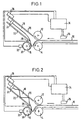
- FIG. 1 shows a folding unit according to the invention for processing a paper sheet 10.
- a first folding roller 12 is arranged vertically above a second folding roller 14.
- Another third folding roller 16 is horizontal next to the second folding roller 14 arranged. All three folding rollers 12, 14 and 16 are driven together and point the same peripheral speed.
- the folding rollers 12 and 14 or 14 and 16 rotate opposite each other.
- FIG. 1 shows the point in time at which the fold is formed the compression space formed between the three folding rollers 12, 14 and 16 the two counter-rotating folding rollers 14 and 16 is detected. This wrinkle is then drawn in and the sheet is subsequently pulled down from the folder conveyed out, for example to another folder in a folder. This in The folding unit shown in FIG.
- FIG. 1 furthermore has a folding pocket 18 with one on the Stowage space between the folding rollers 12, 14 and 16 adjacent pocket mouth.
- the Pocket mouth in turn is through a pocket upper lip 20 and a pocket lower lip 22 educated.
- a Pocket stop 24 To limit the length of the sheet inserted into the folding pocket is a Pocket stop 24 provided.
- the sensor 26 can also start the print image on the sheet 10 detect. He enters both when passing through the leading edge of the sheet 10 and then Signal off when the printed image of the sheet 10 passes under the sensor 26.
- Point of time the fold formation is detected by a sensor 28, which is on the pocket lower lip 22nd is arranged. At the point in time of the fold formation shown in FIG in the folding pocket 18 extending leg of the sheet 10 on the pocket lower lip 22 and exerts pressure on this so that the pocket lower lip 22 is deflected. This Deflection is detected by the sensor 28, for example as Strain gauge arrangement is formed.
- the folding roller 16 is at her Provide circumference with teeth 30. These teeth 30 pass a sensor 32 which is formed, for example, by an optical sensor.
- a sensor 32 which is formed, for example, by an optical sensor.
- One of the sensors 32 Sequence of pulses issued by a counter in an evaluation and Control unit 34 are counted. Since the number of teeth 30 on the folding roller 16 is known is, can in the evaluation and control unit 34 based on the counted pulses and the Known extent of the folding rollers 12, 14 and 16 also determines the length of the conveyed sheet become.
- the signals from sensors 26, 28 and 30 are used by evaluation and control unit 34 Provided.
- the control unit 34 controls an actuating device 36 which Pocket stop 24 in the folding pocket 18 adjusted.
- the pocket folder according to the invention is during a learning phase shown in which a setpoint of the promoted between the first and second time Arc length is determined. This setpoint is available after completion of the learning phase Control unit 34 available.
- Figure 2 shows the pocket folding unit of Figure 1 at increased production speed or changed paper stiffness, so that the inserted in the folding pocket 18 of the Bow 10 is excessively deformed.
- the formation of folds has thus been promoted to a greater arc length than that in FIG. 1 shown time of the fold formation in the lem phase.
- Deviation of the actual value of the arc length between the first time the Leading edge of the sheet 10 passes under the sensor 26, and the second time, to which the fold formation by the deflection of the pocket lower lip 22 by the sensor 28 is found was funded.
- This deviation of the actual value from the setpoint will determined by the evaluation and control unit 34, and the evaluation and control unit 34 then controls the actuating device 36 in such a way that the pocket stop 24 in Moves towards the stuffer box, resulting in less sheet length in the folding pocket 18 or the stowage space is promoted.
- By moving the pocket stop 24 in Direction towards the stuffer box and in the opposite direction can be a Regulation of the determined actual value of the conveyed sheet length to that in the learning phase certain setpoint can be reached.
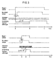
- FIG. 3 shows the timing of the sensor signals from sensors 26, 28 and 32 of Figures 1 and 2 shown schematically.
- 3 are the Sensor signals at low speed, i.e. the state of FIG. 1.
- the sheet / print image sensor 26 detects the sheet entry.
- a correction value Lr is thereby determined, which is necessary for a regulation on the beginning of the print image of a sheet.
- the fold formation which is determined by the signal from the sensor 28, the Deflection of the pocket lower lip 22 is detected.
- the lower diagram in FIG. 3 corresponds to the timing of the sensor signals in FIG the state shown in FIG. 2 at a higher speed.
- the sheet inlet / print image sensor 26 detects the sheet inlet, and two pulses of the incremental encoder 32 later the beginning of the printed image on the sheet is determined. This corresponds to the correction value Lr.
- the bow deforms into the folding pocket, as shown in Fig. 2, wave-like, so that a greater arc length in the folding pocket is conveyed before the crease can form.
- the time B too which the sensor 28 detects the formation of folds, therefore occurs later, so that between Sheet entry A and fold formation B an arc length Ls + DL is promoted.
- the control unit 34 must therefore the steep motor 36 control that this shifts the folding pocket stop 24 until the between Sheet entry A and fold formation B determined pulse number back to the target value Ls corresponds.
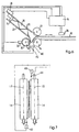
- a second embodiment of the pocket folding unit according to the invention is in the figures 4 and 5.
- a value of the conveyed arc length is here with the help of the signals optical sensor 40 is determined, the closest possible to the pocket mouth of the folding pocket 18th is arranged between the pocket bars.
- the optical sensor 40 is when the Front edge of the sheet covered and released at its outlet, so that the inlet of the Front edge of the sheet 10 in the folding pocket 18 and the outlet of the front edge of the Sheet 10 can be detected after folding.
- the formation of the wrinkle in the The compression space between the folding rollers 12, 14 and 16 is dashed in FIG. 4 shown.
- the between the time of entry of the leading edge of the sheet 10 in the folding pocket 18 and its outlet from the folding pocket 18 are conveyed sheet length, as in the embodiment shown in Figures 1 and 2, using the on the Folding roller 16 arranged teeth 30, the sensor 32 and the evaluation and control unit 34 determined by the between the covering and the release of the sensor 40th occurring pulses of the sensor 32, which correspond to path increments, are counted.
- the measured conveyed sheet length corresponds to that of the sheet lying flat twice the distance from the sensor 40 to the pocket stop 24 plus that for the Formation of the upsetting fold in the sheet length promoted sheet size.
- Figure 5 shows the pocket folder of Figure 4 with increased production speed or reduced paper stiffness.
- the compression fold which forms in the compression space between the folding rollers 12, 14 and 16 is again shown in dashed lines. It can be seen that, in the conditions shown in FIG. 5, an increased length of sheet was conveyed into the folding pocket 18 and the fold break is consequently displaced. When the front edge of the sheet 10 enters the folding pocket 18, the sheet 10 is not yet compressed, and when the front edge of the sheet 10 runs out of the folding pocket 18, the sheet 10 is no longer compressed. If, in the learning phase shown in FIG. 4, a nominal value of the conveyed sheet length Ls has been detected, a length Ls + DL is detected by the sensor 40 under the conditions shown in FIG.
- Pocket folding unit is particularly easy to carry out on the one hand because it is used to determine the the times of the relevant sheet length are only relevant to an optical sensor 40 is required.
- the pocket folding unit shown is particularly susceptible to faults because through the optical sensor 40 the passage of the leading edge of the sheet 10 under the Sensor 40 is detected and not the detection of a relatively small deflection of a Component is required at the time of the fold formation.
- a third embodiment of the pocket folding unit according to the invention is in the figures 6 and 7. With the same reference numerals as in Figures 1 and 2 designated components in FIGS. 6 and 7 are corresponding to those in FIGS. 1 and 2 described trained.
- a value of the conveyed sheet length can be found in this Embodiment of the invention now determine that first again a first Time is determined at which the leading edge of the sheet 10 defines a certain one Passed the place of the sheet path.
- the sensor 26 can be at any distance per se in front of the pocket mouth or as close as possible to the pocket mouth of the folding pocket 18 be attached. As soon as the sensor 26, which is preferably an optical sensor is formed, the passage past the sheet leading edge of sheet 10 can be registered this signal in turn can be passed on to the evaluation and control unit.
- the Evaluation and control unit 34 capable of receiving pulses up to a second Counting signal.
- this is second signal is now achieved in that a front behind the folding rollers 14 and 16th arranged control light barrier, which consists of a transmitter 40 and a receiver 42 exists, is interrupted.
- a light barrier use that works with any electromagnetic radiation per se, here a light barrier with a very narrow beam path is preferred. It is Particularly advantageous is a laser beam source and a corresponding laser sensor to use.
- the transmitter 40 and the receiver 42 are, as shown in FIG. 7, arranged obliquely to the folding rollers 14 and 16.
- the transmitter 40 outgoing light beam 44 emitted so that it is not parallel to the two axes 15th and 17 of the folding rollers 14 and 16 runs. Rather, the aim is the light beam 44 to be emitted from the light source 40 so that it is in a positive or negative An angle of preferably up to 20 ° runs relative to one of the axes 15 or 17.
- Arrangement of the transmitter 40 and the receiver 42 ensures that the paper path of the sheet folded immediately before intersects the ray path and accordingly a signal is generated, which in turn is sent to the evaluation and control unit 34 is forwarded.
- the second point of time determined in this way can be used accordingly the procedure described in the previous figures a Wen for the determine the length of the conveyed sheet. If this value because of one in the previous Figures already described compression of the arch does not match the stored setpoint corresponds, can in turn via the evaluation and control unit 34 Fold pocket stop 24 are moved until the desired arc length is reached.
Landscapes
- Folding Of Thin Sheet-Like Materials, Special Discharging Devices, And Others (AREA)
- Auxiliary Devices For And Details Of Packaging Control (AREA)
- Sewing Machines And Sewing (AREA)
- Details Of Garments (AREA)
- Container Filling Or Packaging Operations (AREA)
- Sheet Holders (AREA)
Abstract
Description
- Figur 1 eine schematische Darstellung einer ersten Ausführungsform der Erfindung,
- Figur 2 eine schematische Darstellung der Ausführungsform der Figur 1 bei höherer Bogengeschwindigkeit oder verringerter Papiersteifigkeit,
- Figur 3 eine schematische Darstellung der zeitlichen Abstimmung der Sensorsignale der Ausführungsform der Figur 1 bei niedriger und hoher Geschwindigkeit,
- Figur 4 eine schematische Darstellung einer zweiten Ausführungsform der Erfindung,
- Figur 5 eine schematische Darstellung der Ausführungsform der Figur 4 bei höherer Bogengeschwindigkeit oder verringerter Papiersteifigkeit,
- Figur 6 eine schematische Darstellung einer dritten Ausführungsform der Erfindung und
- Figur 7 eine schematische Aufsicht auf ein Falzwalzenpaar bei der dritten Ausführungsform der Erfindung.
Claims (29)
- Taschenfalzwerk mit einer Falztasche (18) die einen einstellbaren Taschenanschlag (24) aufweist,
dadurch gekennzeichnet,
daß Mittel (26; 40) zum Erfassen eines ersten Zeitpunkts während des Laufs eines Bogens (10) vom Einlauf in das Taschenfalzwerk bis zum Erreichen des Taschenanschlags (24), Mittel (28; 40) zum Erfassen eines zweiten Zeitpunkts während des Laufs des Bogens (10) von der Falzbildung bis zum Auslauf aus der Falztasche (18) und Mittel (30, 32, 34) zum Bestimmen der zwischen erstem und zweitem Zeitpunkt geförderten Bogenlänge vorgesehen sind. - Taschenfalzwerk nach Anspruch 1,
dadurch gekennzeichnet,
daß die Mittel zum Erfassen des ersten Zeitpunkts als Mittel zum Erfassen des Bogeneinlaufs in das Taschenfalzwerk ausgebildet sind. - Taschenfalzwerk nach Anspruch 2,
dadurch gekennzeichnet,
daß die Mittel zum Erfassen des Bogeneinlaufs wenigstens einen optischen Sensor (26) aufweisen. - Taschenfalzwerk nach einem der vorstehenden Ansprüche,
dadurch gekennzeichnet,
daß die Falztasche (18) einen Taschenmund mit einer Taschenunterlippe (22) aufweist und die Mittel zum Erfassen des zweiten Zeitpunkts als Mittel (28) zum Erfassen der Auslenkung der Taschenunterlippe (22) bei der Falzbildung ausgebildet sind. - Taschenfalzwerk nach Anspruch 4,
dadurch gekennzeichnet,
daß die Mittel zum Erfassen der Auslenkung der Taschenunterlippe als Wegerfassungsmittel ausgebildet sind. - Taschenfalzwerk nach Anspruch 4 oder 5,
dadurch gekennzeichnet,
daß die Mittel zum Erfassen der Auslenkung der Taschenunterlippe wenigstens einen optischen Sensor aufweisen. - Taschenfalzwerk nach Anspruch 4,
dadurch gekennzeichnet,
daß die Mittel zum Erfassen der Auslenkung der Taschenunterlippe eine an der Taschenunterlippe angeordnete Dehnmeßstreifen-Anordnung aufweisen. - Taschenfalzwerk nach Anspruch 4,
dadurch gekennzeichnet,
daß die Mittel zum Erfassen der Auslenkung der Taschenunterlippe einen an der Taschenunterlippe angeordneten piezoelektrischen Sensor aufweisen. - Taschenfalzwerk nach Anspruch 1,
dadurch gekennzeichnet,
daß die Mittel zum Erfassen des ersten Zeitpunkts als Mittel zum Erfassen des Bogeneinlaufs in die Falztasche (18) und die Mittel zum Erfassen des zweiten Zeitpunkts als Mittel zum Erfassen des Bogenauslaufs aus der Falztasche (18) ausgebildet sind. - Taschenfalzwerk nach Anspruch 9,
dadurch gekennzeichnet,
daß die Falztasche (18) einen Taschenmund aufweist und die Mittel zum Erfassen des Bogeneinlaufs und des Bogenauslaufs am Taschenmund angeordnet sind. - Taschenfalzwerk nach Anspruch 9 oder 10,
dadurch gekennzeichnet,
daß die Mittel zum Erfassen des Bogeneinlaufs und die Mittel zum Erfassen des Bogenauslaufs einen gemeinsamen optischen Sensor (40) aufweisen. - Taschenfalzwerk nach einem der vorstehenden Ansprüche,
dadurch gekennzeichnet,
daß die Mittel zum Bestimmen der zwischen erstem und zweitem Zeitpunkt geförderten Bogenlänge einen einer Falzwalze (16) zugeordneten Impulsgeber (30, 32) und eine Zählvorrichtung aufweisen. - Taschenfalzwerk nach Anspruch 1,
dadurch gekennzeichnet,
daß die Mittel zum Erfassen des ersten Zeitpunktes als Mittel zum Erfassen der Bogenvorderkante an einer definierten Position des Bogenlaufweges, und die Mittel zum Erfassen des zweiten Zeitpunktes als Mittel zum Erfassen der Falzkante des gefalzten Bogens ausgebildet sind. - Taschenfalzwerk nach Anspruch 13,
dadurch gekennzeichnet,
daß die Mittel zum Erfassen der Falzkante des gefalzten Bogens eine Lichtschranke beinhalten, die einen Sender zum Aussenden elektromagnetischer Strahlung sowie einen zugehörigen Empfänger zum Empfangen der elektromagnetischen Strahlung beinhaltet. - Taschenfalzwerk nach Anspruch 13,
dadurch gekennzeichnet,
daß die gerade Verbindungslinie zwischen dem Sender (40) und dem Empfänger (42) in einem Winkel zur Achse (15, 17) der Falzwalzen (14, 16) angeordnet sind. - Taschenfalzwerk nach einem der Ansprüche 13 bis 15,
dadurch gekennzeichnet,
daß die Lichtschranke eine Laserlichtsendeeinheit und einen Laserlichtempfänger aufweist. - Taschenfalzwerk nach einem der vorstehenden Ansprüche,
dadurch gekennzeichnet,
daß die einstellbare Falztasche (18) wenigstens eine elektrisch aktivierbare Stelleinrichtung (36) aufweist und eine Regeleinheit (34) vorgesehen ist, die die Signale der Mittel (26; 40) zum Erfassen des ersten Zeitpunkts, der Mittel (28; 40) zum Erfassen des zweiten Zeitpunkts und der Mittel (30, 32, 34) zum Bestimmen der zwischen erstem und zweitem Zeitpunkt geförderten Bogenlänge verarbeitet und die elektrisch aktivierbare Stelleinrichtung (36) der Falztasche (18) ansteuert. - Taschenfalzwerk nach Anspruch 17,
dadurch gekennzeichnet,
daß die elektrisch aktivierbare Stelleinrichtung (36) einen Falztaschenanschlag (24) verstellt. - Taschenfalzwerk nach Anspruch 17 oder 18,
dadurch gekennzeichnet,
daß die elektrisch aktivierbare Stelleinrichtung die Falztaschenweite verstellt. - Taschenfalzwerk nach einem der Ansprüche 17 bis 19,
dadurch gekennzeichnet,
daß die elektrisch aktivierbare Stelleinrichtung wenigstens eine Falztaschenlippe verstellt. - Taschenfalzwerk nach einem der Ansprüche 17 bis 21,
dadurch gekennzeichnet,
daß die elektrisch aktivierbare Stelleinrichtung zur Veränderung des Stauchraums den Falztaschenmund verschiebt. - Taschenfalzwerk nach einem der Ansprüche 17 bis 21,
dadurch gekennzeichnet,
daß die Regeleinheit einen Mikroprozessor aufweist. - Taschenfalzwerk nach einem der vorstehenden Ansprüche,
dadurch gekennzeichnet,
daß wenigstens ein optischer Sensor (26) zur Erfassung des Druckbildbeginns auf einem einlaufenden Bogen (10) vorgesehen ist. - Taschenfalzwerk nach einem der Ansprüche 17 bis 22 und Anspruch 19,
dadurch gekennzeichnet,
daß die Regeleinheit (34) weiterhin das Signal des Sensor (26) zur Erfassung des Druckbildbeginns verarbeitet. - Verfahren zur Registerregelung eines Taschenfalzwerks nach einem der Ansprüche 1 bis 24,
dadurch gekennzeichnet,
daß in einer Lernphase ein Sollwert (Ls) der zwischen erstem und zweitem Zeitpunkt geförderten Bogenlänge bestimmt wird und während des Produktionsbetriebs ein ermittelter Istwert (Ls + DL) der geförderten Bogenlänge durch Ansteuern der elektrischen Stelleinrichtung (36) auf den Sollwert (Ls) geregelt wird. - Verfahren nach Anspruch 25,
dadurch gekennzeichnet,
daß bei einer Regelung auf den Druckbildbeginn eines Bogens (10) für jeden einlaufenden Bogen (10) eine Längendifferenz (Lr) zwischen Bogeneinlauf und Druckbildbeginn des Bogens (10) bestimmt wird. - Verfahren nach Anspruch 26,
dadurch gekennzeichnet,
daß Schwankungen der Längendifferenz im Sinne einer konstanten Relation zwischen Druckbildbeginn und Lage des Falzbruches ausgeregelt werden. - Verfahren nach Anspruch 26 oder 27,
dadurch gekennzeichnet,
daß der Sollwert (Ls) mit der Längendifferenz (Lr) zwischen Bogeneinlauf und Druckbildbeginn korrigiert wird. - Falzmaschine mit wenigstens einen Taschenfalzwerk nach einem der Ansprüche 1 bis 24.
Applications Claiming Priority (2)
| Application Number | Priority Date | Filing Date | Title |
|---|---|---|---|
| DE19860070 | 1998-12-23 | ||
| DE19860070A DE19860070A1 (de) | 1998-12-23 | 1998-12-23 | Taschenfalzwerk und Verfahren zur Registerregelung eines Taschenfalzwerks |
Publications (3)
| Publication Number | Publication Date |
|---|---|
| EP1013589A2 true EP1013589A2 (de) | 2000-06-28 |
| EP1013589A3 EP1013589A3 (de) | 2002-05-15 |
| EP1013589B1 EP1013589B1 (de) | 2004-11-10 |
Family
ID=7892674
Family Applications (1)
| Application Number | Title | Priority Date | Filing Date |
|---|---|---|---|
| EP99125009A Expired - Lifetime EP1013589B1 (de) | 1998-12-23 | 1999-12-15 | Taschenfalzwerk und Verfahren zur Registerregelung eines Taschenfalzwerks |
Country Status (6)
| Country | Link |
|---|---|
| US (1) | US6641514B1 (de) |
| EP (1) | EP1013589B1 (de) |
| JP (1) | JP4173615B2 (de) |
| AT (1) | ATE282002T1 (de) |
| DE (2) | DE19860070A1 (de) |
| PT (1) | PT1013589E (de) |
Cited By (1)
| Publication number | Priority date | Publication date | Assignee | Title |
|---|---|---|---|---|
| EP4389664A1 (de) * | 2022-12-20 | 2024-06-26 | Heidelberger Druckmaschinen AG | Bogenfalzmaschine mit makulaturausschleusung |
Families Citing this family (11)
| Publication number | Priority date | Publication date | Assignee | Title |
|---|---|---|---|---|
| US20050090932A1 (en) * | 2003-10-27 | 2005-04-28 | Heidelberger Druckmaschinen Aktiengesellschaft | Apparatus for processing preliminary products in the graphics industry |
| ITBO20040405A1 (it) * | 2004-06-25 | 2004-09-25 | Gd Spa | Metodo ed unita' per ripiegare coupon in una macchina impacchettatrice |
| DE102004058647A1 (de) * | 2004-12-06 | 2006-06-14 | Heidelberger Druckmaschinen Ag | Vorrichtung zum Falzen flacher Werkstücke |
| DE102005009132B4 (de) * | 2005-03-01 | 2019-03-14 | Manroland Goss Web Systems Gmbh | Verfahren zur Steuerung bzw. Regelung eines Falzapparats einer Druckmaschine |
| DE102005013361B4 (de) * | 2005-03-23 | 2017-04-13 | Manroland Web Systems Gmbh | Verfahren zur Regelung eines Falzapparats einer Druckmaschine |
| ES2333740T3 (es) * | 2006-02-28 | 2010-02-26 | M T C - Macchine Trasformazione Carta S.R.L. | Maquina de interplegado modular que permite un cambio de formato simple. |
| US7537556B2 (en) * | 2007-10-25 | 2009-05-26 | Xerox Corporation | High capacity knife folding system |
| US8187158B2 (en) * | 2008-12-03 | 2012-05-29 | Petratto S.R.L. | Paper folding station |
| CN102548883B (zh) * | 2009-08-26 | 2014-08-13 | 好利用国际株式会社 | 折纸装置 |
| JP5018933B2 (ja) * | 2010-06-28 | 2012-09-05 | コニカミノルタビジネステクノロジーズ株式会社 | 用紙折畳装置 |
| EP2646355A1 (de) * | 2010-11-30 | 2013-10-09 | OCE-Technologies B.V. | Blattfaltgerät, blattfaltverfahren und druckersystem mit dem blattfaltgerät |
Family Cites Families (14)
| Publication number | Priority date | Publication date | Assignee | Title |
|---|---|---|---|---|
| US5037364A (en) * | 1988-04-04 | 1991-08-06 | Baumfolder Corporation | Gatefold apparatus and method |
| EP0379712B1 (de) * | 1989-01-25 | 1994-03-09 | Faltex Ag | Vorrichtung zum zickzackförmigen Falten einer Papierbahn |
| US5092832A (en) * | 1990-06-11 | 1992-03-03 | Roll Systems, Inc. | Method and apparatus for creasing continuous web |
| DE9006855U1 (de) * | 1990-06-19 | 1990-08-30 | Bernd Diehm Ingenieurbüro für elektronische Steuerungen GmbH, 8902 Neusäß | Vorrichtung zur Bestimmung der Lage des Falzes bei einem Bogen |
| EP0511488A1 (de) * | 1991-03-26 | 1992-11-04 | Mathias Bäuerle GmbH | Papierfalzmaschine mit einstellbaren Falzwalzen |
| DE4114105C2 (de) * | 1991-04-30 | 1994-09-15 | Baeuerle Gmbh Mathias | Stauchfalzmaschine |
| US5514066A (en) * | 1994-09-01 | 1996-05-07 | Pitney Bowes Inc. | Buckle chute folding machine for different length sheets |
| FR2729939B1 (fr) * | 1995-01-31 | 1997-04-18 | Neopost Ind | Dispositif d'assistance au reglage de dimensions de pliage dans une machine plieuse insereuse |
| PT732293E (pt) * | 1995-03-15 | 2002-07-31 | Heidelberger Druckmasch Ag | Processo para a optimizacao do desempenho operacional de uma maquina dobradeira |
| DE29516265U1 (de) * | 1995-10-13 | 1995-12-07 | Mathias Bäuerle GmbH, 78112 St Georgen | Stauchfalzmaschine mit einer Sammelfalztasche |
| US5980439A (en) * | 1996-01-19 | 1999-11-09 | Output Technology Solutions Of California, Inc. | Folding apparatus |
| US5967963A (en) * | 1996-11-26 | 1999-10-19 | Grapha-Holding Ag | Apparatus for folding paper sheets |
| DE19747997A1 (de) * | 1997-10-30 | 1999-05-12 | Stahl Gmbh & Co Maschf | Taschenfalzwerk und Verfahren zur Registerregelung eines Taschenfalzwerks |
| US6024682A (en) * | 1998-11-23 | 2000-02-15 | Xerox Corporation | Automatically continuously variable fold position sheet folding system with automatic length and skew correction |
-
1998
- 1998-12-23 DE DE19860070A patent/DE19860070A1/de not_active Withdrawn
-
1999
- 1999-12-15 AT AT99125009T patent/ATE282002T1/de not_active IP Right Cessation
- 1999-12-15 PT PT99125009T patent/PT1013589E/pt unknown
- 1999-12-15 DE DE59911040T patent/DE59911040D1/de not_active Expired - Lifetime
- 1999-12-15 EP EP99125009A patent/EP1013589B1/de not_active Expired - Lifetime
- 1999-12-22 JP JP36513599A patent/JP4173615B2/ja not_active Expired - Fee Related
- 1999-12-23 US US09/472,058 patent/US6641514B1/en not_active Expired - Fee Related
Cited By (1)
| Publication number | Priority date | Publication date | Assignee | Title |
|---|---|---|---|---|
| EP4389664A1 (de) * | 2022-12-20 | 2024-06-26 | Heidelberger Druckmaschinen AG | Bogenfalzmaschine mit makulaturausschleusung |
Also Published As
| Publication number | Publication date |
|---|---|
| EP1013589A3 (de) | 2002-05-15 |
| DE59911040D1 (de) | 2004-12-16 |
| PT1013589E (pt) | 2005-03-31 |
| JP2000198620A (ja) | 2000-07-18 |
| EP1013589B1 (de) | 2004-11-10 |
| JP4173615B2 (ja) | 2008-10-29 |
| DE19860070A1 (de) | 2000-06-29 |
| ATE282002T1 (de) | 2004-11-15 |
| US6641514B1 (en) | 2003-11-04 |
Similar Documents
| Publication | Publication Date | Title |
|---|---|---|
| EP0913352B1 (de) | Taschenfalzwerk und Verfahren zur Registerregelung eines Taschenfalzwerks | |
| DE4241502C2 (de) | Vorrichtung zum fortwährenden Zuführen einzelner Blätter zu einem Blattverarbeitungsabschnitt einer Blattverarbeitungseinrichtung | |
| DE19844974B4 (de) | Ausrichtesystem zum Ausrichten einer Führungskante eines Aufzeichnungsträgers | |
| DE60010027T2 (de) | Verfahren und Vorrichtung zur Querausrichtung eines Blattes mit einem auf diesem zu übertragenden Bild | |
| EP1013589B1 (de) | Taschenfalzwerk und Verfahren zur Registerregelung eines Taschenfalzwerks | |
| EP0475095A1 (de) | Vorrichtung zum Ausrichten einer kontinuierlichen Folienbahn relativ zu einer zweiter Bahn | |
| EP2030924A1 (de) | Einrichtung zum Verarbeiten von Druckprodukten | |
| EP3507097A1 (de) | Bogenverarbeitende maschine und verfahren zur überwachung eines bogenlaufs | |
| DE19950603A1 (de) | Verfahren zur Steuerung der Bogenzufuhr zu einer bogenverarbeitenden Maschine | |
| EP0411366A2 (de) | Falzapparat zum Herstellen von längs- und/oder quergefalzten Produkten | |
| EP0156326B1 (de) | Faltmaschine zum Falten von Bogen | |
| EP0513482B1 (de) | Seitenmarken- und Überziehkontrolle einer Rotations-Bogendruckmaschine | |
| DE19508254C5 (de) | Verfahren zum Transportieren von einzelnen Bogen | |
| EP3059195B1 (de) | Falzvorrichtung und Verfahren | |
| DE69503816T2 (de) | Vorrichtung zum Falten eines Bogens in zwei Richtungen | |
| EP1588965B1 (de) | Verfahren zur Lagekontrolle eines in einer Falzmaschine transportierten Bogens | |
| EP3077306B1 (de) | Vorrichtung sowie verfahren zum schneiden eines bahnmaterials in teilbahnen und spreizen der teilbahnen | |
| DE102011003925B4 (de) | Verfahren zur Ermittlung einer Schräglage eines durch Längsfalzen eines Produktes durch einen Längsfalzapparat erzeugten Falzbruchs sowie Längsfalzapparat mit Mitteln zur Ermittlung einer derartigen Schräglage | |
| EP3599074B1 (de) | Vorrichtung zur herstellung von standbodenbeuteln | |
| EP1666396B1 (de) | Vorrichtung zum Falzen flacher Werkstücke | |
| EP1457310A2 (de) | Verfahren und Vorrichtung zum Herstellen von Briefumschlägen und dergleichen | |
| EP0934221B1 (de) | Verfahren und vorrichtungen zur eingabe von blattmaterial in einen drucker oder kopierer | |
| DE102004015101B4 (de) | Verfahren und Sensoreinrichtung zum Steuern eines endlosen, eine Naht aufweisenden Transportmediums für eine Druckmaschine | |
| EP4434927B1 (de) | Verfahren zum überwachen eines falzvorgangs in einer taschenfalzmaschine | |
| DE102024132945B3 (de) | Druckmaschinen-Betriebsverfahren |
Legal Events
| Date | Code | Title | Description |
|---|---|---|---|
| PUAI | Public reference made under article 153(3) epc to a published international application that has entered the european phase |
Free format text: ORIGINAL CODE: 0009012 |
|
| AK | Designated contracting states |
Kind code of ref document: A2 Designated state(s): AT BE CH CY DE DK ES FI FR GB GR IE IT LI LU MC NL PT SE |
|
| AX | Request for extension of the european patent |
Free format text: AL;LT;LV;MK;RO;SI |
|
| PUAL | Search report despatched |
Free format text: ORIGINAL CODE: 0009013 |
|
| AK | Designated contracting states |
Kind code of ref document: A3 Designated state(s): AT BE CH CY DE DK ES FI FR GB GR IE IT LI LU MC NL PT SE |
|
| AX | Request for extension of the european patent |
Free format text: AL;LT;LV;MK;RO;SI |
|
| 17P | Request for examination filed |
Effective date: 20020403 |
|
| AKX | Designation fees paid |
Designated state(s): AT BE CH CY DE DK ES FI FR GB GR IE IT LI LU MC NL PT SE |
|
| 17Q | First examination report despatched |
Effective date: 20030408 |
|
| GRAP | Despatch of communication of intention to grant a patent |
Free format text: ORIGINAL CODE: EPIDOSNIGR1 |
|
| GRAS | Grant fee paid |
Free format text: ORIGINAL CODE: EPIDOSNIGR3 |
|
| GRAA | (expected) grant |
Free format text: ORIGINAL CODE: 0009210 |
|
| AK | Designated contracting states |
Kind code of ref document: B1 Designated state(s): AT BE CH CY DE DK ES FI FR GB GR IE IT LI LU MC NL PT SE |
|
| PG25 | Lapsed in a contracting state [announced via postgrant information from national office to epo] |
Ref country code: SE Free format text: LAPSE BECAUSE OF FAILURE TO SUBMIT A TRANSLATION OF THE DESCRIPTION OR TO PAY THE FEE WITHIN THE PRESCRIBED TIME-LIMIT Effective date: 20041110 Ref country code: NL Free format text: LAPSE BECAUSE OF FAILURE TO SUBMIT A TRANSLATION OF THE DESCRIPTION OR TO PAY THE FEE WITHIN THE PRESCRIBED TIME-LIMIT Effective date: 20041110 Ref country code: IE Free format text: LAPSE BECAUSE OF FAILURE TO SUBMIT A TRANSLATION OF THE DESCRIPTION OR TO PAY THE FEE WITHIN THE PRESCRIBED TIME-LIMIT Effective date: 20041110 Ref country code: GB Free format text: LAPSE BECAUSE OF FAILURE TO SUBMIT A TRANSLATION OF THE DESCRIPTION OR TO PAY THE FEE WITHIN THE PRESCRIBED TIME-LIMIT Effective date: 20041110 Ref country code: FR Free format text: LAPSE BECAUSE OF NON-PAYMENT OF DUE FEES Effective date: 20041110 Ref country code: FI Free format text: LAPSE BECAUSE OF FAILURE TO SUBMIT A TRANSLATION OF THE DESCRIPTION OR TO PAY THE FEE WITHIN THE PRESCRIBED TIME-LIMIT Effective date: 20041110 Ref country code: CY Free format text: LAPSE BECAUSE OF FAILURE TO SUBMIT A TRANSLATION OF THE DESCRIPTION OR TO PAY THE FEE WITHIN THE PRESCRIBED TIME-LIMIT Effective date: 20041110 |
|
| REG | Reference to a national code |
Ref country code: GB Ref legal event code: FG4D Free format text: NOT ENGLISH |
|
| REG | Reference to a national code |
Ref country code: CH Ref legal event code: EP |
|
| PG25 | Lapsed in a contracting state [announced via postgrant information from national office to epo] |
Ref country code: AT Free format text: LAPSE BECAUSE OF NON-PAYMENT OF DUE FEES Effective date: 20041215 |
|
| REG | Reference to a national code |
Ref country code: IE Ref legal event code: FG4D Free format text: GERMAN |
|
| REF | Corresponds to: |
Ref document number: 59911040 Country of ref document: DE Date of ref document: 20041216 Kind code of ref document: P |
|
| PG25 | Lapsed in a contracting state [announced via postgrant information from national office to epo] |
Ref country code: MC Free format text: LAPSE BECAUSE OF NON-PAYMENT OF DUE FEES Effective date: 20041231 Ref country code: BE Free format text: LAPSE BECAUSE OF NON-PAYMENT OF DUE FEES Effective date: 20041231 |
|
| PG25 | Lapsed in a contracting state [announced via postgrant information from national office to epo] |
Ref country code: LU Free format text: LAPSE BECAUSE OF NON-PAYMENT OF DUE FEES Effective date: 20050110 |
|
| PG25 | Lapsed in a contracting state [announced via postgrant information from national office to epo] |
Ref country code: GR Free format text: LAPSE BECAUSE OF FAILURE TO SUBMIT A TRANSLATION OF THE DESCRIPTION OR TO PAY THE FEE WITHIN THE PRESCRIBED TIME-LIMIT Effective date: 20050210 Ref country code: DK Free format text: LAPSE BECAUSE OF FAILURE TO SUBMIT A TRANSLATION OF THE DESCRIPTION OR TO PAY THE FEE WITHIN THE PRESCRIBED TIME-LIMIT Effective date: 20050210 |
|
| PG25 | Lapsed in a contracting state [announced via postgrant information from national office to epo] |
Ref country code: ES Free format text: LAPSE BECAUSE OF FAILURE TO SUBMIT A TRANSLATION OF THE DESCRIPTION OR TO PAY THE FEE WITHIN THE PRESCRIBED TIME-LIMIT Effective date: 20050221 |
|
| REG | Reference to a national code |
Ref country code: PT Ref legal event code: SC4A Free format text: AVAILABILITY OF NATIONAL TRANSLATION Effective date: 20050207 |
|
| NLV1 | Nl: lapsed or annulled due to failure to fulfill the requirements of art. 29p and 29m of the patents act | ||
| GBV | Gb: ep patent (uk) treated as always having been void in accordance with gb section 77(7)/1977 [no translation filed] |
Effective date: 20041110 |
|
| REG | Reference to a national code |
Ref country code: IE Ref legal event code: FD4D |
|
| BERE | Be: lapsed |
Owner name: HEIDELBERGER DRUCKMASCHINEN A.G. Effective date: 20041231 |
|
| PLBE | No opposition filed within time limit |
Free format text: ORIGINAL CODE: 0009261 |
|
| STAA | Information on the status of an ep patent application or granted ep patent |
Free format text: STATUS: NO OPPOSITION FILED WITHIN TIME LIMIT |
|
| 26N | No opposition filed |
Effective date: 20050811 |
|
| EN | Fr: translation not filed | ||
| EN | Fr: translation not filed | ||
| PGFP | Annual fee paid to national office [announced via postgrant information from national office to epo] |
Ref country code: IT Payment date: 20061231 Year of fee payment: 8 |
|
| BERE | Be: lapsed |
Owner name: *HEIDELBERGER DRUCKMASCHINEN A.G. Effective date: 20041231 |
|
| PG25 | Lapsed in a contracting state [announced via postgrant information from national office to epo] |
Ref country code: IT Free format text: LAPSE BECAUSE OF NON-PAYMENT OF DUE FEES Effective date: 20071215 |
|
| PGFP | Annual fee paid to national office [announced via postgrant information from national office to epo] |
Ref country code: DE Payment date: 20131231 Year of fee payment: 15 |
|
| PGFP | Annual fee paid to national office [announced via postgrant information from national office to epo] |
Ref country code: CH Payment date: 20141218 Year of fee payment: 16 |
|
| PGFP | Annual fee paid to national office [announced via postgrant information from national office to epo] |
Ref country code: PT Payment date: 20141124 Year of fee payment: 16 |
|
| REG | Reference to a national code |
Ref country code: DE Ref legal event code: R119 Ref document number: 59911040 Country of ref document: DE |
|
| PG25 | Lapsed in a contracting state [announced via postgrant information from national office to epo] |
Ref country code: DE Free format text: LAPSE BECAUSE OF NON-PAYMENT OF DUE FEES Effective date: 20150701 |
|
| REG | Reference to a national code |
Ref country code: PT Ref legal event code: MM4A Free format text: LAPSE DUE TO NON-PAYMENT OF FEES Effective date: 20160615 |
|
| REG | Reference to a national code |
Ref country code: CH Ref legal event code: PL |
|
| PG25 | Lapsed in a contracting state [announced via postgrant information from national office to epo] |
Ref country code: PT Free format text: LAPSE BECAUSE OF NON-PAYMENT OF DUE FEES Effective date: 20160615 |
|
| PG25 | Lapsed in a contracting state [announced via postgrant information from national office to epo] |
Ref country code: CH Free format text: LAPSE BECAUSE OF NON-PAYMENT OF DUE FEES Effective date: 20151231 Ref country code: LI Free format text: LAPSE BECAUSE OF NON-PAYMENT OF DUE FEES Effective date: 20151231 |