EP1013624A2 - Keramische Zusammensetzung für Hochfrequenzanwendungen, dielektrischer Resonator, dielektrischer Filter, dielektrischer Duplexer und Kommunikationsvorrichtung - Google Patents
Keramische Zusammensetzung für Hochfrequenzanwendungen, dielektrischer Resonator, dielektrischer Filter, dielektrischer Duplexer und Kommunikationsvorrichtung Download PDFInfo
- Publication number
- EP1013624A2 EP1013624A2 EP99125122A EP99125122A EP1013624A2 EP 1013624 A2 EP1013624 A2 EP 1013624A2 EP 99125122 A EP99125122 A EP 99125122A EP 99125122 A EP99125122 A EP 99125122A EP 1013624 A2 EP1013624 A2 EP 1013624A2
- Authority
- EP
- European Patent Office
- Prior art keywords
- dielectric
- dielectric ceramic
- frequency
- rare earth
- ceramic composition
- Prior art date
- Legal status (The legal status is an assumption and is not a legal conclusion. Google has not performed a legal analysis and makes no representation as to the accuracy of the status listed.)
- Granted
Links
- 239000000203 mixture Substances 0.000 title claims abstract description 129
- 239000000919 ceramic Substances 0.000 title claims abstract description 70
- 238000004891 communication Methods 0.000 title claims description 10
- 229910052761 rare earth metal Inorganic materials 0.000 claims abstract description 47
- 229910052791 calcium Inorganic materials 0.000 claims abstract description 14
- 229910052712 strontium Inorganic materials 0.000 claims abstract description 14
- 229910052719 titanium Inorganic materials 0.000 claims abstract description 12
- FDQGNLOWMMVRQL-UHFFFAOYSA-N Allobarbital Chemical compound C=CCC1(CC=C)C(=O)NC(=O)NC1=O FDQGNLOWMMVRQL-UHFFFAOYSA-N 0.000 claims abstract description 5
- 229910052779 Neodymium Inorganic materials 0.000 claims description 19
- 229910052746 lanthanum Inorganic materials 0.000 claims description 15
- 238000010586 diagram Methods 0.000 claims description 12
- 229910052777 Praseodymium Inorganic materials 0.000 claims description 11
- 229910052772 Samarium Inorganic materials 0.000 claims description 11
- 229910052727 yttrium Inorganic materials 0.000 claims description 11
- 230000008878 coupling Effects 0.000 claims description 10
- 238000010168 coupling process Methods 0.000 claims description 10
- 238000005859 coupling reaction Methods 0.000 claims description 10
- 230000005672 electromagnetic field Effects 0.000 claims description 5
- 229910052684 Cerium Inorganic materials 0.000 claims description 3
- 229910052692 Dysprosium Inorganic materials 0.000 claims description 3
- 229910052691 Erbium Inorganic materials 0.000 claims description 3
- 229910052787 antimony Inorganic materials 0.000 claims description 3
- 239000011575 calcium Substances 0.000 description 71
- 239000011777 magnesium Substances 0.000 description 38
- 230000003247 decreasing effect Effects 0.000 description 28
- 239000010936 titanium Substances 0.000 description 17
- VTYYLEPIZMXCLO-UHFFFAOYSA-L Calcium carbonate Chemical compound [Ca+2].[O-]C([O-])=O VTYYLEPIZMXCLO-UHFFFAOYSA-L 0.000 description 12
- 239000000843 powder Substances 0.000 description 12
- 238000010304 firing Methods 0.000 description 11
- 239000002994 raw material Substances 0.000 description 10
- BPUBBGLMJRNUCC-UHFFFAOYSA-N oxygen(2-);tantalum(5+) Chemical compound [O-2].[O-2].[O-2].[O-2].[O-2].[Ta+5].[Ta+5] BPUBBGLMJRNUCC-UHFFFAOYSA-N 0.000 description 9
- 229910001936 tantalum oxide Inorganic materials 0.000 description 9
- 239000013078 crystal Substances 0.000 description 8
- VYPSYNLAJGMNEJ-UHFFFAOYSA-N Silicium dioxide Chemical compound O=[Si]=O VYPSYNLAJGMNEJ-UHFFFAOYSA-N 0.000 description 6
- 229910000019 calcium carbonate Inorganic materials 0.000 description 6
- 230000007423 decrease Effects 0.000 description 6
- BDAGIHXWWSANSR-NJFSPNSNSA-N hydroxyformaldehyde Chemical compound O[14CH]=O BDAGIHXWWSANSR-NJFSPNSNSA-N 0.000 description 6
- 239000000395 magnesium oxide Substances 0.000 description 6
- CPLXHLVBOLITMK-UHFFFAOYSA-N magnesium oxide Inorganic materials [Mg]=O CPLXHLVBOLITMK-UHFFFAOYSA-N 0.000 description 6
- AXZKOIWUVFPNLO-UHFFFAOYSA-N magnesium;oxygen(2-) Chemical compound [O-2].[Mg+2] AXZKOIWUVFPNLO-UHFFFAOYSA-N 0.000 description 6
- 238000004519 manufacturing process Methods 0.000 description 6
- 238000005259 measurement Methods 0.000 description 6
- 229910000018 strontium carbonate Inorganic materials 0.000 description 6
- 239000000463 material Substances 0.000 description 5
- GNTDGMZSJNCJKK-UHFFFAOYSA-N divanadium pentaoxide Chemical compound O=[V](=O)O[V](=O)=O GNTDGMZSJNCJKK-UHFFFAOYSA-N 0.000 description 4
- 230000000694 effects Effects 0.000 description 4
- MRELNEQAGSRDBK-UHFFFAOYSA-N lanthanum oxide Inorganic materials [O-2].[O-2].[O-2].[La+3].[La+3] MRELNEQAGSRDBK-UHFFFAOYSA-N 0.000 description 4
- ZKATWMILCYLAPD-UHFFFAOYSA-N niobium pentoxide Chemical compound O=[Nb](=O)O[Nb](=O)=O ZKATWMILCYLAPD-UHFFFAOYSA-N 0.000 description 4
- KTUFCUMIWABKDW-UHFFFAOYSA-N oxo(oxolanthaniooxy)lanthanum Chemical compound O=[La]O[La]=O KTUFCUMIWABKDW-UHFFFAOYSA-N 0.000 description 4
- 238000005245 sintering Methods 0.000 description 4
- 229910052718 tin Inorganic materials 0.000 description 4
- 229910011255 B2O3 Inorganic materials 0.000 description 3
- GWEVSGVZZGPLCZ-UHFFFAOYSA-N Titan oxide Chemical compound O=[Ti]=O GWEVSGVZZGPLCZ-UHFFFAOYSA-N 0.000 description 3
- 239000000654 additive Substances 0.000 description 3
- -1 and the like) Chemical compound 0.000 description 3
- 239000011230 binding agent Substances 0.000 description 3
- 229910052681 coesite Inorganic materials 0.000 description 3
- 229910052906 cristobalite Inorganic materials 0.000 description 3
- XGZVUEUWXADBQD-UHFFFAOYSA-L lithium carbonate Chemical compound [Li+].[Li+].[O-]C([O-])=O XGZVUEUWXADBQD-UHFFFAOYSA-L 0.000 description 3
- 229910052808 lithium carbonate Inorganic materials 0.000 description 3
- 238000000034 method Methods 0.000 description 3
- 231100000989 no adverse effect Toxicity 0.000 description 3
- 229910001404 rare earth metal oxide Inorganic materials 0.000 description 3
- 239000000377 silicon dioxide Substances 0.000 description 3
- 229910052682 stishovite Inorganic materials 0.000 description 3
- 229910052905 tridymite Inorganic materials 0.000 description 3
- QPLDLSVMHZLSFG-UHFFFAOYSA-N CuO Inorganic materials [Cu]=O QPLDLSVMHZLSFG-UHFFFAOYSA-N 0.000 description 2
- 229910003080 TiO4 Inorganic materials 0.000 description 2
- MCMNRKCIXSYSNV-UHFFFAOYSA-N Zirconium dioxide Chemical compound O=[Zr]=O MCMNRKCIXSYSNV-UHFFFAOYSA-N 0.000 description 2
- GHPGOEFPKIHBNM-UHFFFAOYSA-N antimony(3+);oxygen(2-) Chemical compound [O-2].[O-2].[O-2].[Sb+3].[Sb+3] GHPGOEFPKIHBNM-UHFFFAOYSA-N 0.000 description 2
- 230000006866 deterioration Effects 0.000 description 2
- 239000003989 dielectric material Substances 0.000 description 2
- 239000011656 manganese carbonate Substances 0.000 description 2
- 229910000016 manganese(II) carbonate Inorganic materials 0.000 description 2
- GNRSAWUEBMWBQH-UHFFFAOYSA-N nickel(II) oxide Inorganic materials [Ni]=O GNRSAWUEBMWBQH-UHFFFAOYSA-N 0.000 description 2
- 229910052715 tantalum Inorganic materials 0.000 description 2
- XOLBLPGZBRYERU-UHFFFAOYSA-N tin dioxide Chemical compound O=[Sn]=O XOLBLPGZBRYERU-UHFFFAOYSA-N 0.000 description 2
- ZNOKGRXACCSDPY-UHFFFAOYSA-N tungsten(VI) oxide Inorganic materials O=[W](=O)=O ZNOKGRXACCSDPY-UHFFFAOYSA-N 0.000 description 2
- 229910052725 zinc Inorganic materials 0.000 description 2
- XLOMVQKBTHCTTD-UHFFFAOYSA-N zinc oxide Inorganic materials [Zn]=O XLOMVQKBTHCTTD-UHFFFAOYSA-N 0.000 description 2
- 229910052726 zirconium Inorganic materials 0.000 description 2
- PNEYBMLMFCGWSK-UHFFFAOYSA-N aluminium oxide Inorganic materials [O-2].[O-2].[O-2].[Al+3].[Al+3] PNEYBMLMFCGWSK-UHFFFAOYSA-N 0.000 description 1
- 230000001413 cellular effect Effects 0.000 description 1
- 229910052593 corundum Inorganic materials 0.000 description 1
- 229910001845 yogo sapphire Inorganic materials 0.000 description 1
Images



Classifications
-
- H—ELECTRICITY
- H01—ELECTRIC ELEMENTS
- H01P—WAVEGUIDES; RESONATORS, LINES, OR OTHER DEVICES OF THE WAVEGUIDE TYPE
- H01P7/00—Resonators of the waveguide type
- H01P7/10—Dielectric resonators
-
- C—CHEMISTRY; METALLURGY
- C04—CEMENTS; CONCRETE; ARTIFICIAL STONE; CERAMICS; REFRACTORIES
- C04B—LIME, MAGNESIA; SLAG; CEMENTS; COMPOSITIONS THEREOF, e.g. MORTARS, CONCRETE OR LIKE BUILDING MATERIALS; ARTIFICIAL STONE; CERAMICS; REFRACTORIES; TREATMENT OF NATURAL STONE
- C04B35/00—Shaped ceramic products characterised by their composition; Ceramics compositions; Processing powders of inorganic compounds preparatory to the manufacturing of ceramic products
- C04B35/01—Shaped ceramic products characterised by their composition; Ceramics compositions; Processing powders of inorganic compounds preparatory to the manufacturing of ceramic products based on oxide ceramics
- C04B35/46—Shaped ceramic products characterised by their composition; Ceramics compositions; Processing powders of inorganic compounds preparatory to the manufacturing of ceramic products based on oxide ceramics based on titanium oxides or titanates
- C04B35/462—Shaped ceramic products characterised by their composition; Ceramics compositions; Processing powders of inorganic compounds preparatory to the manufacturing of ceramic products based on oxide ceramics based on titanium oxides or titanates based on titanates
-
- C—CHEMISTRY; METALLURGY
- C04—CEMENTS; CONCRETE; ARTIFICIAL STONE; CERAMICS; REFRACTORIES
- C04B—LIME, MAGNESIA; SLAG; CEMENTS; COMPOSITIONS THEREOF, e.g. MORTARS, CONCRETE OR LIKE BUILDING MATERIALS; ARTIFICIAL STONE; CERAMICS; REFRACTORIES; TREATMENT OF NATURAL STONE
- C04B35/00—Shaped ceramic products characterised by their composition; Ceramics compositions; Processing powders of inorganic compounds preparatory to the manufacturing of ceramic products
- C04B35/01—Shaped ceramic products characterised by their composition; Ceramics compositions; Processing powders of inorganic compounds preparatory to the manufacturing of ceramic products based on oxide ceramics
- C04B35/46—Shaped ceramic products characterised by their composition; Ceramics compositions; Processing powders of inorganic compounds preparatory to the manufacturing of ceramic products based on oxide ceramics based on titanium oxides or titanates
- C04B35/462—Shaped ceramic products characterised by their composition; Ceramics compositions; Processing powders of inorganic compounds preparatory to the manufacturing of ceramic products based on oxide ceramics based on titanium oxides or titanates based on titanates
- C04B35/465—Shaped ceramic products characterised by their composition; Ceramics compositions; Processing powders of inorganic compounds preparatory to the manufacturing of ceramic products based on oxide ceramics based on titanium oxides or titanates based on titanates based on alkaline earth metal titanates
-
- C—CHEMISTRY; METALLURGY
- C04—CEMENTS; CONCRETE; ARTIFICIAL STONE; CERAMICS; REFRACTORIES
- C04B—LIME, MAGNESIA; SLAG; CEMENTS; COMPOSITIONS THEREOF, e.g. MORTARS, CONCRETE OR LIKE BUILDING MATERIALS; ARTIFICIAL STONE; CERAMICS; REFRACTORIES; TREATMENT OF NATURAL STONE
- C04B35/00—Shaped ceramic products characterised by their composition; Ceramics compositions; Processing powders of inorganic compounds preparatory to the manufacturing of ceramic products
- C04B35/01—Shaped ceramic products characterised by their composition; Ceramics compositions; Processing powders of inorganic compounds preparatory to the manufacturing of ceramic products based on oxide ceramics
- C04B35/495—Shaped ceramic products characterised by their composition; Ceramics compositions; Processing powders of inorganic compounds preparatory to the manufacturing of ceramic products based on oxide ceramics based on vanadium, niobium, tantalum, molybdenum or tungsten oxides or solid solutions thereof with other oxides, e.g. vanadates, niobates, tantalates, molybdates or tungstates
Definitions
- the present invention relates to a high-frequency dielectric ceramic composition and electronic devices using the same.
- dielectric ceramics are widely used as materials for a dielectric resonator, a dielectric filter, a circuit board, etc., which are mounted on electronic apparatuses used in a high-frequency region such as a microwave or millimeter wave region, or the like, such as a cellular telephone, a personal communication equipment, a satellite broadcasting receiver, etc.
- Dielectric characteristics required for such high-frequency dielectric ceramics include (1) a high dielectric constant ( ⁇ r) for complying with the need for miniaturization because the wavelength of electromagnetic waves is shortened to 1/( ⁇ r ) 1/2 in a dielectric material, (2) a low dielectric loss, i.e., a high Q value, (3) excellent temperature stability of resonance frequency, i.e., the temperature coefficient ( f) of the resonance frequency of about 0 (ppm/°C), etc.
- dielectric ceramic compositions such as Ba(Zn, Ta)O 3 system compositions (Japanese Patent Publication No. Sho-58-25068), Ba(Sn, Mg, Ta)O 3 system compositions (Japanese Patent Publication No. Hei-3-341 64), (Zr, Sn)TiO 4 system compositions (Japanese Patent Publication No. Hei-4-59267), Ba 2 Ti 9 O 20 (Japanese Laid-open Patent Application No. Sho-61-10806).
- dielectric ceramic compositions such as Ba(Zn, Ta)O 3 system compositions (Japanese Patent Publication No. Sho-58-25068), Ba(Sn, Mg, Ta)O 3 system compositions (Japanese Patent Publication No. Hei-3-341 64), (Zr, Sn)TiO 4 system compositions (Japanese Patent Publication No. Hei-4-59267), Ba 2 Ti 9 O 20 (Japanese Laid-open Patent Application No. Sho-61-10806).
- Ba(Zn, Ta)O 3 based and Ba(Sn, Mg, Ta)O 3 based materials have a high Q value of 150, 000 to 300, 000 (at 1 GHz) but have a relatively low dielectric constant ( ⁇ r ) of 24 to 30.
- (Zr, Sn)TiO 4 based materials and Ba 2 Ti 9 O 20 have a relatively high dielectric constant ( ⁇ r ) of 37 to 40, and a high Q value of 50, 000 to 60, 000 (at 1 GHz), but it is difficult to realize a relatively high dielectric constant ( ⁇ r ) of over 40, for example.
- ⁇ r dielectric constant
- Q value for example, 15, 000 (at 1 GHz)
- Another high-frequency dielectric ceramic composition of the present invention comprises a rare earth element (Ln), Mg, Ta, Ti, and M (M: at least one of Ca and Sr), and has a composition represented by the composition formula by molar ratio, yLn(Mg 2/3 Ta 1/3 )O 3 -(1-y)MTiO 3 , wherein y is in the range of 0.2 ⁇ y ⁇ 0.7.
- the rare earth element (Ln) is preferably at least one of Y, La, Ce, Pr, Nd, Sm, Dy and Er, more preferably La.
- the rare earth element (Ln, Lm) is preferably at least one of Y, La, Pr, Nd, and Sm.
- the element M is preferably Ca.
- the rare earth element (Ln, Lm) is more preferably at least one of La, Nd, and Sm.
- the rare earth element (Ln, Lm) is most preferably La.
- the rare earth element (Ln, Lm) is at least one of Y, La, Pr, Nd, and Sm.
- the element M is preferably Ca.
- the rare earth element (Ln, Lm) is preferably at least one of La, Nd, and Sm.
- the rare earth element (Ln, Lm) is most preferably La.
- a dielectric resonator of the present invention is operated by electromagnetic field coupling of dielectric ceramic with input/output terminals, wherein the dielectric ceramic is composed of any one of the above-described high-frequency dielectric ceramic compositions.
- a dielectric filter of the present invention comprises the above dielectric resonator including external coupling means.
- a dielectric duplexer of the present invention comprises at least two dielectric filters, input/output connecting means connected to each of the dielectric filters, and antenna connecting means connected to the dielectric filters in common, wherein at least one of the dielectric filters is the above-described dielectric filter.
- a communication device of the present invention comprises the above dielectric duplexer, a transmitting circuit connected to at least one input/output connecting means of the dielectric duplexer, a receiving circuit connected to at least one input/output connecting means different from the input/output connecting means connected to the transmitting circuit, and an antenna connected to antenna connecting means of the dielectric duplexer.
- Fig. 1 is a sectional view showing the fundamental structure of a dielectric resonator 1 comprising a ceramic composition of the present invention.
- the dielectric resonator 1 comprising a metallic case 2, and a columnar dielectric ceramic 4 arranged in the space of the metallic case to be supported by a support 3.
- Input and output terminal 5 and 6 are held by the metallic case 2 in a state insulated from the metallic case 2.
- the dielectric ceramic 4 is operated by electromagnetic field coupling with the input and output terminals 5 and 6 so that only signals at a predetermined frequency input from the input terminal 5 are output from the output terminal 6.
- the dielectric ceramic 4 provided in the dielectric resonator 1 is composed of a high-frequency dielectric ceramic composition of the present invention.
- FIG. 2 is a block diagram showing an example of communication devices of the present invention.
- a communication device 10 comprises a dielectric duplexer 12, a transmitting circuit 14, a receiving circuit 16, and an antenna 18.
- the transmitting circuit 14 is connected to input connecting means 20 of the dielectric duplexer 12; the receiving circuit 16 is connected to output connecting means 22 of the dielectric duplexer 12.
- the antenna 18 is connected to antenna connecting means 24 of the dielectric duplexer 12.
- the dielectric duplexer 12 comprises two dielectric filters 26 and 28. Each of the dielectric filters 26 and 28 is formed by connecting external coupling means to the dielectric resonator of the present invention. In this embodiment, for example, external coupling means 30 is connected to each of the input/output terminals of the dielectric resonator 1.
- One 26 of the dielectric filters 26 and 28 is connected between the input connecting means 20 and the other dielectric filter 28; the other dielectric filter 28 is connected between one 26 of the dielectric filters 26 and 28 and the output connecting means 22.
- a is selected in the range of 0.100 ⁇ a ⁇ 0.350. This is because with a ⁇ 0.100, the Q value is decreased, while with 0.350 ⁇ a, the absolute value of the temperature coefficient ( ⁇ f) of the resonance frequency exceeds 80 ppm/°C.
- the parameter a is more preferably selected in the range of 0.150 ⁇ a ⁇ 0.200 because it is possible to obtain the characteristic that the temperature coefficient ( ⁇ f) of the resonance frequency is 28 ppm/°C or less.
- the parameters b and c are selected in the ranges of 0.067 ⁇ b ⁇ 0.233 and 0.033 ⁇ c ⁇ 0.117, respectively. This is because with b ⁇ 0.067 or c ⁇ 0.033, the Q value is decreased, while with 0.233 ⁇ b or 0.117 ⁇ c, the absolute value of the temperature coefficient ( ⁇ f) of the resonance frequency exceeds 80 ppm/°C.
- b is limited in the range of 0.100 ⁇ b ⁇ 0.133
- c is limited in the range of 0.050 ⁇ c ⁇ 0.067 because it is possible to obtain the characteristic that the temperature coefficient ( ⁇ f) of the resonance frequency is 28 ppm/°C or less.
- the parameter d is selected in the range of 0.150 ⁇ d ⁇ 0.400. This is because with d > 0.400, the Q value is decreased, while with d ⁇ 0.150, the absolute value of the temperature coefficient ( ⁇ f) of the resonance frequency exceeds 80 ppm/°C.
- d is in the range of 0.300 ⁇ d ⁇ 0.350 because it is possible to obtain the characteristic that the temperature coefficient ( ⁇ f) of the resonance frequency is 28 ppm/°C or less.
- the parameter e is in the range of 0.150 ⁇ e ⁇ 0.400. This is because with 0.400 ⁇ e, the Q value is decreased, while with e ⁇ 0.150, the absolute value of the temperature coefficient ( ⁇ f) of the resonance frequency exceeds 80 ppm/°C.
- the parameter e is more preferably selected in the range of 0.300 ⁇ e ⁇ 0.350 because it is possible to obtain the characteristic that the temperature coefficient ( ⁇ f) of the resonance frequency is 28 ppm/°C or less.
- the rare earth element (Ln) at least one of Y, La, Ce, Pr, Nd, Sm, Dy and Er can be used. Of these elements, La is more preferably used. This is because the use of La can increase the dielectric constant ( ⁇ r ) and Q value as compared with the other elements.
- small amounts of additives may be added in ranges having no adverse effect on the object of the present invention.
- addition of 0.01 to 0.1 % by weight of SiO 2 , ZnO, MnO, B 2 O 3 , NiO, CuO, Li 2 CO 3 , or the like decreases the firing temperature by 20 to 30°C, but deteriorates less characteristics.
- addition of 1 to 3 % by weight of Al 2 O 3 , Sb 2 O 3 , V 2 O 5 , WO 3 , or the like permits fine control of the dielectric constant and temperature characteristic, thereby obtaining excellent dielectric ceramic.
- the high-frequency dielectric ceramic composition of the present invention is represented by the composition formula yLn(Mg 2/3 Ta 1/3 )O 3 -(1-y)MTiO 3 more specific than the above composition formula by molar ratio, and y can be changed in the range of 0.2 ⁇ y ⁇ 0.7 to change the temperature coefficient ( ⁇ f) of the resonance frequency to any desired values with 0 (ppm/°C) as the center.
- the dielectric constant ( ⁇ r ) is as high as 25 to 60, and the Q value is 15, 000 or more.
- high-purity rare earth oxides La 2 O 3 , and the like
- magnesium oxide MgO
- tantalum oxide Ta 2 O 3
- calcium carbonate CaCO 3
- strontium carbonate SrCO 3
- titanium oxide TiO 2
- y represents the ratio of Ln(Mg 2/3 T 1/3 )O 3 to MTiO 3 in the composition formula: yLn(Mg 2/3 Ta 1/3 )O 3 -(1-y)MTiO 3 .
- a, b, c, d, and e respectively represent the molar ratios of the components in the composition by molar ratio: aLnO x/2 -bMgO-cTaO 5/2 -dMO-eTiO 2 (wherein M is Ca and/or Sr).
- Samples 53 to 74 shown in Table 2 respectively contain the various rare earth element oxides shown in the column "Rare earth element" in place of La 2 O 3 shown in Table 1, Samples 53 to 68 respectively have compositions corresponding to Sample 17 shown in Table 1, and Samples 69 to 74 respectively have compositions corresponding to Sample 48 shown in Table 1.
- a powder prepared at each of the composition ratios shown in Tables 1 and 2 was wet-milled for 16 hours by using a ball mill, dehydrated, dried and then calcined at 1100 to 1300°C for 3 hours. An appropriate amount of binder was added to the resultant calcined powder, and the mixture was again ground for 16 hours by using the ball mill to obtain a powder.
- the thus-obtained powder was molded to a disk shape by using a press under a pressure of 1, 000 to 2, 000 kg/cm 2 , and then fired in the atmosphere at 1, 400 to 1, 500°C for 4 to 10 hours to obtain a sintered compact having a diameter of 10 mm and a thickness of 5 mm.
- Tables 1 and 2 indicate that the samples in the range of the present invention can exhibit high Q values while maintaining dielectric constants at high values in the microwave band.
- the reason for limiting a in the range of 0.100 ⁇ a ⁇ 0.350 is that with a ⁇ 0.100, like in Samples 1 and 2, the Q value is decreased, while with a > 0.350, like in Samples 35, 36, 37, 45 and 46, the absolute value of the temperature coefficient ( ⁇ f) of the resonance frequency exceeds 80 ppm/°C.
- the absolute value of the temperature coefficient ( ⁇ f) of the resonance frequency is 28 ppm/°C or less.
- the reason for limiting b in the range of 0.067 ⁇ b ⁇ 0.233 is that with b ⁇ 0.067, like in Samples 1, 3 and 8, the Q value is decreased, while with b > 0.233, like in Samples 29, 34, 36, 37, 45, and 46, the absolute value of the temperature coefficient ( ⁇ f) of the resonance frequency exceeds 80 ppm/°C.
- the absolute value of the temperature coefficient ( ⁇ f) of the resonance frequency is 28 ppm/°C or less.
- the reason for limiting c in the range of 0.033 ⁇ c ⁇ 0.117 is that with c ⁇ 0.033, like in Samples 1,7, and 8, the Q value is decreased, while with c > 0.117, like in Samples 29, 30, 36, 37, 46 and 46, the absolute value of the temperature coefficient ( ⁇ f) of the resonance frequency exceeds 80 ppm/°C.
- the absolute value of the temperature coefficient ( ⁇ f) of the resonance frequency is 28 ppm/°C or less.
- the reason for limiting d in the range of 0.150 ⁇ a ⁇ 0.400 is that with d > 0.400, like in Samples 1 and 6, the Q value is decreased, while with d ⁇ 0.150, like in Samples 31, 36, 37, 45, and 46, the absolute value of the temperature coefficient ( ⁇ f) of the resonance frequency exceeds 80 ppm/°C.
- the reason for limiting e in the range of 0.150 ⁇ a ⁇ 0.400 is that with e > 0.400, like in Samples 1 and 4, the Q value is decreased, while with e ⁇ 0.150, like in Samples 33, 36, 37, 45, and 46, the absolute value of the temperature coefficient ( ⁇ f) of the resonance frequency exceeds 80 ppm/°C.
- the absolute value of the temperature coefficient ( ⁇ f) of the resonance frequency is 28 ppm/°C or less.
- Comparison of Sample 17 shown in Table 1 with Samples 53 to 68 shown in Table 2 indicates that it is preferable to use La as the rare earth element.
- the use of La can further increase both the dielectric constant ( ⁇ r ) and the Q value.
- Samples having "y" values described in the table have compositions represented by the composition formula: yLn(Mg 2/3 Ta 1/3 )O 3 -(1-y)MTiO 3 and the main crystal is composed of a perovskite crystal phase.
- the temperature coefficient ( ⁇ f) of the resonance frequency can be changed to any desired values with 0 ppm/°C as a center by changing y in the range of 0.2 ⁇ y ⁇ 0.7.
- These samples exhibit dielectric constants ( ⁇ r ) of as high as about 25 to 60, and most of the samples exhibit Q values of 15000 or more.
- the present invention can provide a high-frequency dielectric ceramic composition having both a high dielectric constant and high Q value, and permitting a decrease in the temperature coefficient ( ⁇ f) of the resonance frequency, and a dielectric ceramic obtained by sintering the composition can be advantageously used for high-frequency devices such as a dielectric resonator, etc.
- the high-frequency dielectric ceramic composition of the present invention has a composition represented by the composition formula: yLn(Mg 2/3 Ta 1/3 )O 3 -(1-y)MTiO 3 (wherein Ln is a rare earth element, and M is at least one of Ca and Sr), wherein y is in the range of 0.2 ⁇ y ⁇ 0.7.
- the main crystal is composed of a perovskite crystal phase. In this case, y can be changed to control the temperature coefficient ( ⁇ f) of the resonance frequency to any desired values with 0 (ppm/°C) as a center.
- a high-frequency dielectric ceramic composition comprises a rare earth element (Ln and Lm), Mg, Ta, Ti and M (M: at least one of Ca and Sr), and has a composition represented by the composition formula: xMTi a O 1+2a -yLn(Mg 2/3 Ta 1/3 ) b O (3+3b)/2 -zLm(Mg 1/2 Ti 1/2 ) c O (3+3c)/2 (wherein x, y and Z are by mol%), wherein a, b, c, x, y and z are respectively in the following ranges.
- the parameter a is in the range of 0.850 ⁇ a ⁇ 1.050. This is because with a ⁇ 0.950, or a > 1.050, the Q value is decreased, failing to achieve the object of the present invention.
- the parameter b is in the range of 0.900 ⁇ a ⁇ 1.050. This is because with b ⁇ 0.900, or b > 1.050, the Q value is decreased.
- the parameter c is in the range of 0.900 ⁇ c ⁇ 1.050. This is because with c ⁇ 0.900, or c > 1.050, the Q value is decreased.
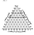
- the parameters x, y and z are on a polygonal line or inside the line (except on lines A'B' and C'D'), which connects points A', B', C' and D' in a ternary composition diagram of Fig. 3.
- the temperature coefficient ( ⁇ f) of the resonance frequency exceeds +50 ppm/°C
- white with x, y, and z outside the line B'C' the temperature coefficient ( ⁇ f) of the resonance frequency is shifted to the minus side from -50 ppm/°C.
- the reason for excluding the range on the line C'D' is the following.
- x With constant x, as z decreases, the temperature coefficient ( ⁇ f) of the resonance frequency is shifted to the minus side. Therefore, in order to obtain the same temperature coefficient ( ⁇ f) of the resonance frequency, it is necessary that x is increased as z is decreased.
- the rare earth element (Ln and Lm) Y, La, Pr, Nd, Sm, or the like is preferably used.
- La, Nd or Sm is more preferably used, and La is most preferably used.
- the use of Nd or Sm improves the Q value, and the use of La can further increase the dielectric constant ( ⁇ r ) and the Q value.
- high-purity calcium carbonate (CaCO 3 ), strontium carbonate (SrCO 3 ), titanium oxide (TiO 2 ), rare earth oxides (La 2 O 3 , and the like), magnesium oxide (MgO), and tantalum oxide (Ta 2 O 3 ) were prepared.
- These raw materials were also mixed to obtain compositions represented by the composition formula: XMTi a O 1+2a -yLn(Mg 2/3 Ta 1/3 ) b O (3+3b)/2 -zLm(Mg 1/2 Ti 1/2 ) c O (3+3c)/2 (wherein x, y and Z are by mol%) shown in Table 4.
- Samples 1041 to 1056 shown in Table 4 respectively contain the various rare earth elements shown in the column "Rare earth element” in Table 4 in place of La in the composition formula shown in Table 3, Samples 1041 to 1052 respectively have compositions corresponding to Sample 1016 shown in Table 3, and Samples 1053 to 1056 respectively have compositions corresponding to Sample 1035 shown in Table 3.
- a powder of these mixed raw materials was wet-milled for 16 hours by using a ball mill, dehydrated, dried and then calcined at 1100 to 1300°C for 3 hours.
- An appropriate amount of binder was added to the resultant calcined powder, and the mixture was again wet-ground for 16 hours by using the ball mill to obtain a powder.
- the thus-obtained powder was molded to a disk shape by using a press under a pressure of 1000 to 2000 kg/cm 2 , and then fired in the atmosphere at 1350 to 1450°C for 4 hours to obtain ceramic having a diameter of 10 mm and a thickness of 5 mm.
- the main crystal exhibited a perovskite crystal phase.
- Tables 3 and 4 indicate that the samples in the range of the present invention can exhibit high Q values while maintaining dielectric constants at high values in the microwave band.
- the reason for limiting a in the range of 0.950 ⁇ a ⁇ 1.050 is that with a ⁇ 0.950, like in Samples 1011 and 1030, and with 1.050 ⁇ a, like in Samples 1021 and 1040, the Q value is decreased, failing to achieve the object of the present invention.
- the reason for limiting b in the range of 0.900 ⁇ a ⁇ 1.050 is that with b ⁇ 0.900, like in Samples 1013 and 1032, and with b > 1.050, like in Samples 1019 and 1038, the Q value is decreased.
- the reason for limiting c in the range of 0.900 ⁇ a ⁇ 1.050 is that with c ⁇ 0.900, like in Samples 1015 and 1034, and with c > 1.050, like in Samples 1017 and 1036, the Q value is decreased.
- the temperature coefficient ( f) of the resonance frequency exceeds +50 ppm/°C
- the temperature coefficient ( f) of the resonance frequency is shifted to the minus side from -50 ppm/°C.
- the reason for excluding the range on the line C'D' is the following.
- the temperature coefficient ( ⁇ f) of the resonance frequency is shifted to the minus side.
- this property is exhibited in Samples 1004 to 1006, 1016, 1022 and 1023 shown in Table 3. Therefore, in order to obtain the same temperature coefficient ( ⁇ f) of the resonance frequency, it is necessary that x is increased as z is decreased.
- the Q value is decreased by increasing x, and thus x is as low as possible for obtaining a high Q value.
- comparison between Samples 1008 and 1016 shown in Table 3, which show substantially the same temperature coefficient of the resonance frequency indicates that in Sample 1016 having high z, a higher Q value is obtained.
- Comparison of Sample 1016 shown in Table 3 with Samples 1041 to 1052 shown in Table 4, and comparison of Sample 1005 shown in Table 3 with Samples 1053 to 1056 shown in Table 4 indicate that it is most preferable to use La as the rare earth element.
- the use of La can obtain both high dielectric constant ( ⁇ r ) and high Q value.
- Comparison between Samples 1041, 1044, 1047, and 1050 indicates that the use of Nd or Sm as a rare earth element can obtain a higher Q value, as compared with the use of Y or Pr.
- small amounts of additives may be added in ranges having no adverse effect on the object of the present invention.
- addition of 0.01 to 0.1 % by weight of SiO 2 , MnCO 3 , B 2 O 3 , ZnO, NiO, CuO, Li 2 CO 3 , or the like decreases the firing temperature by 20 to 30°C, while suppressing deterioration in characteristics.
- addition of 1 to 3 % by weight of ZrO 2 , SnO 2 , Nb 2 O 5 , WO 3 , or the like permits fine control of the dielectric constant ( ⁇ r ) and temperature characteristic, thereby obtaining excellent dielectric ceramic.
- the present invention can provide a high-frequency dielectric ceramic composition having a high dielectric constant ( ⁇ r ) of as high as 37 to 51, and a Q value of as high as 20, 000 (at 1GHz) or more, and permitting fine control of the temperature coefficient ( ⁇ f) of the resonance frequency to any desired values with 0 (ppm/°C) as a center.
- ⁇ r high dielectric constant
- ⁇ f temperature coefficient
- dielectric ceramic having the above-described composition can be used for manufacturing a dielectric resonator, a dielectric filter, a dielectric duplexer, and a communication device, each having good characteristics.
- Another high-frequency dielectric ceramic composition comprises a rare earth element (Ln and Lm), Mg, Ta, Sb, Ti and M (M: at least one of Ca and Sr), and has a composition represented by the composition formula, xMTi a O 1+2a -yLn(Mg 2/3 Ta 1/3 ) b O (3+3b)/2 -zLm(Mg 2/3 Sb 1/3 ) c O (3+3c)/2 (wherein x, y and Z are by mol%), wherein a, b, c, x, y and z are respectively in the following ranges.
- the parameter a is in the range of 0.950 ⁇ a ⁇ 1.050. This is because with a ⁇ 0.950, or a > 1.050, the Q value is decreased, failing to achieve the object of the present invention.
- the parameter b is in the range of 0.900 ⁇ a ⁇ 1.050. This is because with b ⁇ 0.900, or b > 1.050, the Q value is decreased.
- the parameter c is in the range of 0.900 ⁇ c ⁇ 1.050. This is because with c ⁇ 0.900, or c > 1.050, the Q value is decreased.
- the parameters x, y and z are on a polygonal line or inside the line (except on line C"D"), which connects points A", B", C" and D" in a ternary composition diagram of Fig. 4.
- the temperature coefficient ( f) of the resonance frequency exceeds +50 ppm/°C
- the temperature coefficient ( f) of the resonance frequency is shifted to the minus side from -50 ppm/°C.
- the rare earth element (Ln and Lm) Y, La, Pr, Nd, Sm, or the like is preferably used.
- La, Nd or Sm is more preferably used, and La is most preferably used.
- the use of Nd or Sm improves the Q value, and the use of La can further increase the dielectric constant ( ⁇ r ) and the Q value.
- high-purity calcium carbonate (CaCO 3 ), strontium carbonate (SrCO 3 ), titanium oxide (TiO 2 ), rare earth oxides (La 2 O 3 , and the like), magnesium oxide (MgO), tantalum oxide (Ta 2 O 3 ), and antimony oxide (Sb 2 O 3 ) were prepared.
- compositions represented by the composition formula xMTi a O 1+2a -yLa(Mg 2/3 Ta 1/3 ) b O (3+3b)/2 -zLa(Mg 2/3 Sb 1/3 ) c O (3+3c)/2 (wherein x, y and Z are by mol%) shown in Table 5.
- These raw materials were also mixed to obtain compositions represented by the composition formula, XMTi a O 1+2a -XLn(Mg 2/3 Ta 1/3 ) b O (3+3b)/2 -zLm(Mg 2/3 Sb 1/3 ) c O (3+3c)/2 (wherein x, y and Z are by mol%) shown in Table 6.
- Samples 2041 to 2056 shown in Table 6 respectively contain the various rare earth elements shown in the column "Rare earth element” in Table 6 in place of La in the composition formula shown in Table 5, Samples 2041 to 2052 respectively have compositions corresponding to Sample 2016 shown in Table 5, and Samples 2053 to 2056 respectively have compositions corresponding to Sample 2035 shown in Table 5.
- a powder of these mixed raw materials was wet-milled for 16 hours by using a ball mill, dehydrated, dried and then calcined at 1100 to 1300°C for 3 hours.
- An appropriate amount of binder was added to the resultant calcined powder, and the mixture was again wet-ground for 16 hours by using the ball mill to obtain a powder.
- the thus-obtained powder was molded to a disk shape by using a press under a pressure of 1, 000 to 2, 000 kg/cm 2 , and then fired in the atmosphere at 1350 to 1400°C for 4 hours to obtain ceramic having a diameter of 10 mm and a thickness of 5 mm and composed of a perovskite crystal phase as a main crystal.
- Tables 5 and 6 indicate that the samples in the range of the present invention can exhibit high Q values while maintaining dielectric constants at high values in the microwave band.
- the reason for limiting a in the range of 0.950 ⁇ a ⁇ 1.050 is that with a ⁇ 0.950, like in Samples 2011 and 2030, and with a > 1.050, like in Samples 2021 and 2040, the Q value is decreased, failing to achieve the object of the present invention.
- the reason for limiting b in the range of 0.900 ⁇ a ⁇ 1.050 is that with b ⁇ 0.900, like in Samples 2013 and 2032, and with 1.050 ⁇ b, like in Samples 2019 and 2038, the Q value is decreased.
- the reason for limiting c in the range of 0.900 ⁇ a ⁇ 1.050 is that with c ⁇ 0.900, like in Samples 2015 and 2034, and with 1.050 ⁇ c, like in Samples 2017 and 2036, the Q value is decreased.
- the temperature coefficient ( f) of the resonance frequency exceeds +50 ppm/°C
- the temperature coefficient ( f) of the resonance frequency is shifted to the minus side from -50 ppm/°C.
- Comparison of Sample 2016 shown in Table 5 with Samples 2041 to 2052 shown in Table 6, and comparison of Sample 2035 shown in Table 5 with Samples 2053 to 2056 shown in Table 6 indicate that it is most preferable to use La as the rare earth element.
- the use of La can obtain both high dielectric constant ( ⁇ r ) and high Q value.
- Comparison between Samples 2041, 2044, 2047, and 2050 indicates that the use of Nd or Sm as a rare earth element can obtain a higher Q value, as compared with the use of Y or Pr.
- small amounts of additives may be added in ranges having no adverse effect on the object of the present invention.
- addition of 0.01 to 0.1 % by weight of SiO 2 , MnCO 3 , B 2 O 3 , ZnO, NiO, CuO, Li 2 CO 3 , or the like decreases the firing temperature by 10 to 20°C, while suppressing deterioration in characteristics.
- addition of 1 to 3 % by weight of Nb 2 O 5 , V 2 O 5 , WO 3 , or the like permits fine control of the dielectric constant ( ⁇ r ) and temperature characteristic, thereby obtaining excellent dielectric ceramic.
- the present invention can provide a high-frequency dielectric ceramic composition having a high dielectric constant ( ⁇ r ) of as high as 37 to 54, and a Q value of as high as 20000 (at 1GHz) or more, and permitting fine control of the temperature coefficient ( f) of the resonance frequency to any desired values with 0 (ppm/°C) as a center.
- dielectric ceramic having the above-described composition can be used for manufacturing a dielectric resonator, a dielectric filter, a dielectric duplexer, and a communication device, each having good characteristics.
Landscapes
- Engineering & Computer Science (AREA)
- Chemical & Material Sciences (AREA)
- Ceramic Engineering (AREA)
- Manufacturing & Machinery (AREA)
- Materials Engineering (AREA)
- Structural Engineering (AREA)
- Organic Chemistry (AREA)
- Inorganic Insulating Materials (AREA)
- Compositions Of Oxide Ceramics (AREA)
Applications Claiming Priority (6)
| Application Number | Priority Date | Filing Date | Title |
|---|---|---|---|
| JP36638498A JP3376933B2 (ja) | 1998-12-24 | 1998-12-24 | 高周波用誘電体磁器組成物および誘電体共振器 |
| JP33638498 | 1998-12-24 | ||
| JP17571599A JP3575336B2 (ja) | 1999-06-22 | 1999-06-22 | 高周波用誘電体磁器組成物、誘電体共振器、誘電体フィルタ、誘電体デュプレクサおよび通信機装置 |
| JP17571699A JP3598886B2 (ja) | 1999-06-22 | 1999-06-22 | 高周波用誘電体磁器組成物、誘電体共振器、誘電体フィルタ、誘電体デュプレクサおよび通信機装置 |
| JP17571699 | 1999-06-22 | ||
| JP17571599 | 1999-06-22 |
Publications (3)
| Publication Number | Publication Date |
|---|---|
| EP1013624A2 true EP1013624A2 (de) | 2000-06-28 |
| EP1013624A3 EP1013624A3 (de) | 2000-10-04 |
| EP1013624B1 EP1013624B1 (de) | 2008-10-08 |
Family
ID=27324154
Family Applications (1)
| Application Number | Title | Priority Date | Filing Date |
|---|---|---|---|
| EP99125122A Expired - Lifetime EP1013624B1 (de) | 1998-12-24 | 1999-12-16 | Keramische Zusammensetzung für Hochfrequenzanwendungen, dielektrischer Resonator, dielektrischer Filter, dielektrischer Duplexer und Kommunikationsvorrichtung |
Country Status (3)
| Country | Link |
|---|---|
| US (1) | US6245702B1 (de) |
| EP (1) | EP1013624B1 (de) |
| DE (1) | DE69939680D1 (de) |
Cited By (2)
| Publication number | Priority date | Publication date | Assignee | Title |
|---|---|---|---|---|
| EP1172345A1 (de) * | 2000-07-12 | 2002-01-16 | Murata Manufacturing Co., Ltd. | Keramische Zusammensetzung für Hochfrequenzanwendungen, dielektrischer Resonator, dielektrischer Filter, dielektrischer Duplexer und Kommunikationsvorrichtung |
| WO2002062569A1 (fr) * | 2001-02-05 | 2002-08-15 | Ct For Advanced Science & Tech | Structure a couche d'oxyde, procede de production de cette structure, et condensateur et filtre utilisant cette structure |
Families Citing this family (2)
| Publication number | Priority date | Publication date | Assignee | Title |
|---|---|---|---|---|
| JP3562454B2 (ja) * | 2000-09-08 | 2004-09-08 | 株式会社村田製作所 | 高周波用磁器、誘電体アンテナ、支持台、誘電体共振器、誘電体フィルタ、誘電体デュプレクサおよび通信機装置 |
| WO2006098093A1 (ja) * | 2005-03-16 | 2006-09-21 | Murata Manufacturing Co., Ltd. | 高周波用誘電体磁器組成物、誘電体共振器、誘電体フィルタ、誘電体デュプレクサ、及び通信機装置 |
Family Cites Families (9)
| Publication number | Priority date | Publication date | Assignee | Title |
|---|---|---|---|---|
| JPS52157734U (de) * | 1976-05-24 | 1977-11-30 | ||
| JPS63124602A (ja) | 1986-11-14 | 1988-05-28 | Nippon Telegr & Teleph Corp <Ntt> | 対称構造コプレ−ナウエイブガイドアイソレ−タ |
| JPH04287403A (ja) | 1991-03-15 | 1992-10-13 | Ngk Insulators Ltd | エッジガイドモード型アイソレータ |
| JPH05266711A (ja) * | 1992-03-17 | 1993-10-15 | Matsushita Electric Ind Co Ltd | 誘電体磁器組成物 |
| US5356843A (en) * | 1992-09-10 | 1994-10-18 | Matsushita Electric Industrial Co., Ltd. | Dielectric ceramic compositions and dielectric resonators |
| JP3252570B2 (ja) * | 1993-10-15 | 2002-02-04 | 株式会社村田製作所 | 誘電体デュプレクサ |
| KR970001055B1 (ko) * | 1994-06-30 | 1997-01-25 | 한국과학기술연구원 | 고주파용 유전체 조성물 |
| JPH08133834A (ja) * | 1994-09-07 | 1996-05-28 | Sumitomo Metal Ind Ltd | 誘電体磁器組成物及びその製造方法 |
| JP3287978B2 (ja) * | 1995-03-02 | 2002-06-04 | 松下電器産業株式会社 | 誘電体磁器組成物 |
-
1999
- 1999-12-16 DE DE69939680T patent/DE69939680D1/de not_active Expired - Lifetime
- 1999-12-16 EP EP99125122A patent/EP1013624B1/de not_active Expired - Lifetime
- 1999-12-27 US US09/472,398 patent/US6245702B1/en not_active Expired - Fee Related
Cited By (3)
| Publication number | Priority date | Publication date | Assignee | Title |
|---|---|---|---|---|
| EP1172345A1 (de) * | 2000-07-12 | 2002-01-16 | Murata Manufacturing Co., Ltd. | Keramische Zusammensetzung für Hochfrequenzanwendungen, dielektrischer Resonator, dielektrischer Filter, dielektrischer Duplexer und Kommunikationsvorrichtung |
| US6403512B1 (en) | 2000-07-12 | 2002-06-11 | Murata Manufacturing Co., Ltd. | Dielectric ceramic for high frequency, dielectric resonator, dielectric filter, dielectric duplexer and communication unit |
| WO2002062569A1 (fr) * | 2001-02-05 | 2002-08-15 | Ct For Advanced Science & Tech | Structure a couche d'oxyde, procede de production de cette structure, et condensateur et filtre utilisant cette structure |
Also Published As
| Publication number | Publication date |
|---|---|
| DE69939680D1 (de) | 2008-11-20 |
| EP1013624A3 (de) | 2000-10-04 |
| US6245702B1 (en) | 2001-06-12 |
| EP1013624B1 (de) | 2008-10-08 |
Similar Documents
| Publication | Publication Date | Title |
|---|---|---|
| US6549094B2 (en) | High frequency ceramic compact, use thereof, and method of producing the same | |
| EP0915066B1 (de) | Dielektrische keramische zusammensetzung und resonator daraus | |
| EP1020416B1 (de) | Verfahren zur Herstellung von dielektrischem keramischen Material und dielektrischer Resonator | |
| KR100406123B1 (ko) | 고주파용 유전체 세라믹 조성물, 유전체 공진기, 유전체필터, 유전체 듀플렉서 및 통신시스템 | |
| US6369669B1 (en) | Rare-earth ceramic filter | |
| US5525562A (en) | Dielectric ceramic compound | |
| EP1172345B1 (de) | Keramische Zusammensetzung für Hochfrequenzanwendungen, dielektrischer Resonator, dielektrischer Filter, dielektrischer Duplexer und Kommunikationsvorrichtung | |
| US5767030A (en) | High frequency dielectric ceramic composition and fabrication method thereof | |
| US5256639A (en) | Dielectric ceramic composition | |
| JP4839496B2 (ja) | 高周波用誘電体磁器組成物、誘電体共振器、誘電体フィルタ、誘電体デュプレクサ及び通信機装置 | |
| EP0589441B1 (de) | Zusammensetzung dielektrischer Kermamiken | |
| EP1013624A2 (de) | Keramische Zusammensetzung für Hochfrequenzanwendungen, dielektrischer Resonator, dielektrischer Filter, dielektrischer Duplexer und Kommunikationsvorrichtung | |
| JP4513076B2 (ja) | 高周波用誘電体磁器組成物、誘電体共振器、誘電体フィルタ、誘電体デュプレクサおよび通信機装置 | |
| US7056852B2 (en) | High-frequency dielectric ceramic composition, dielectric resonator, dielectric filter, dielectric duplexer and communication system | |
| US6940371B2 (en) | High frequency dielectric ceramic composition, dielectric resonator, dielectric filter, dielectric duplexer, and communication device | |
| US5521130A (en) | Dielectric material for high frequencies | |
| KR100225881B1 (ko) | 마이크로파용 온도보상형 유전체 세라믹 조성물 | |
| JP3598886B2 (ja) | 高周波用誘電体磁器組成物、誘電体共振器、誘電体フィルタ、誘電体デュプレクサおよび通信機装置 | |
| JP3575336B2 (ja) | 高周波用誘電体磁器組成物、誘電体共振器、誘電体フィルタ、誘電体デュプレクサおよび通信機装置 | |
| JP2000233970A (ja) | 高周波用誘電体磁器組成物、誘電体共振器、誘電体フィルタ、誘電体デュプレクサおよび通信機装置 | |
| JPH0778513A (ja) | 誘電体磁器組成物 |
Legal Events
| Date | Code | Title | Description |
|---|---|---|---|
| PUAI | Public reference made under article 153(3) epc to a published international application that has entered the european phase |
Free format text: ORIGINAL CODE: 0009012 |
|
| 17P | Request for examination filed |
Effective date: 19991216 |
|
| AK | Designated contracting states |
Kind code of ref document: A2 Designated state(s): DE FI FR GB IT SE |
|
| AX | Request for extension of the european patent |
Free format text: AL;LT;LV;MK;RO;SI |
|
| PUAL | Search report despatched |
Free format text: ORIGINAL CODE: 0009013 |
|
| AK | Designated contracting states |
Kind code of ref document: A3 Designated state(s): AT BE CH CY DE DK ES FI FR GB GR IE IT LI LU MC NL PT SE |
|
| AX | Request for extension of the european patent |
Free format text: AL;LT;LV;MK;RO;SI |
|
| RIC1 | Information provided on ipc code assigned before grant |
Free format text: 7C 04B 35/465 A, 7C 04B 35/495 B, 7H 01P 7/10 B, 7C 04B 35/462 B, 7C 04B 35/47 B, 7C 01G 35/00 B |
|
| AKX | Designation fees paid |
Free format text: DE FI FR GB IT SE |
|
| 17Q | First examination report despatched |
Effective date: 20020426 |
|
| RAP1 | Party data changed (applicant data changed or rights of an application transferred) |
Owner name: MURATA MANUFACTURING CO., LTD. |
|
| GRAP | Despatch of communication of intention to grant a patent |
Free format text: ORIGINAL CODE: EPIDOSNIGR1 |
|
| GRAS | Grant fee paid |
Free format text: ORIGINAL CODE: EPIDOSNIGR3 |
|
| GRAA | (expected) grant |
Free format text: ORIGINAL CODE: 0009210 |
|
| AK | Designated contracting states |
Kind code of ref document: B1 Designated state(s): DE FI FR GB IT SE |
|
| REG | Reference to a national code |
Ref country code: GB Ref legal event code: FG4D |
|
| REF | Corresponds to: |
Ref document number: 69939680 Country of ref document: DE Date of ref document: 20081120 Kind code of ref document: P |
|
| PG25 | Lapsed in a contracting state [announced via postgrant information from national office to epo] |
Ref country code: FI Free format text: LAPSE BECAUSE OF FAILURE TO SUBMIT A TRANSLATION OF THE DESCRIPTION OR TO PAY THE FEE WITHIN THE PRESCRIBED TIME-LIMIT Effective date: 20081008 |
|
| PLBE | No opposition filed within time limit |
Free format text: ORIGINAL CODE: 0009261 |
|
| STAA | Information on the status of an ep patent application or granted ep patent |
Free format text: STATUS: NO OPPOSITION FILED WITHIN TIME LIMIT |
|
| PG25 | Lapsed in a contracting state [announced via postgrant information from national office to epo] |
Ref country code: SE Free format text: LAPSE BECAUSE OF FAILURE TO SUBMIT A TRANSLATION OF THE DESCRIPTION OR TO PAY THE FEE WITHIN THE PRESCRIBED TIME-LIMIT Effective date: 20090108 Ref country code: IT Free format text: LAPSE BECAUSE OF FAILURE TO SUBMIT A TRANSLATION OF THE DESCRIPTION OR TO PAY THE FEE WITHIN THE PRESCRIBED TIME-LIMIT Effective date: 20081008 |
|
| 26N | No opposition filed |
Effective date: 20090709 |
|
| GBPC | Gb: european patent ceased through non-payment of renewal fee |
Effective date: 20090108 |
|
| REG | Reference to a national code |
Ref country code: FR Ref legal event code: ST Effective date: 20090831 |
|
| PG25 | Lapsed in a contracting state [announced via postgrant information from national office to epo] |
Ref country code: GB Free format text: LAPSE BECAUSE OF NON-PAYMENT OF DUE FEES Effective date: 20090108 |
|
| PG25 | Lapsed in a contracting state [announced via postgrant information from national office to epo] |
Ref country code: FR Free format text: LAPSE BECAUSE OF NON-PAYMENT OF DUE FEES Effective date: 20081231 |
|
| PGFP | Annual fee paid to national office [announced via postgrant information from national office to epo] |
Ref country code: DE Payment date: 20091229 Year of fee payment: 11 |
|
| REG | Reference to a national code |
Ref country code: DE Ref legal event code: R119 Ref document number: 69939680 Country of ref document: DE Effective date: 20110701 |
|
| PG25 | Lapsed in a contracting state [announced via postgrant information from national office to epo] |
Ref country code: DE Free format text: LAPSE BECAUSE OF NON-PAYMENT OF DUE FEES Effective date: 20110701 |