EP1013830A1 - Anordnung und Verfahren zum Verbinden eines Bauelements und einer Kabelstruktur und Hängebrücke mit solchen Anordnungen - Google Patents
Anordnung und Verfahren zum Verbinden eines Bauelements und einer Kabelstruktur und Hängebrücke mit solchen Anordnungen Download PDFInfo
- Publication number
- EP1013830A1 EP1013830A1 EP99401563A EP99401563A EP1013830A1 EP 1013830 A1 EP1013830 A1 EP 1013830A1 EP 99401563 A EP99401563 A EP 99401563A EP 99401563 A EP99401563 A EP 99401563A EP 1013830 A1 EP1013830 A1 EP 1013830A1
- Authority
- EP
- European Patent Office
- Prior art keywords
- cable
- housing
- wedging
- frustoconical
- jaw
- Prior art date
- Legal status (The legal status is an assumption and is not a legal conclusion. Google has not performed a legal analysis and makes no representation as to the accuracy of the status listed.)
- Withdrawn
Links
- 239000000725 suspension Substances 0.000 title claims description 10
- 238000000034 method Methods 0.000 title claims description 8
- 230000006835 compression Effects 0.000 claims abstract description 30
- 238000007906 compression Methods 0.000 claims abstract description 30
- 230000005540 biological transmission Effects 0.000 claims abstract description 15
- 238000010276 construction Methods 0.000 claims abstract description 11
- 239000000463 material Substances 0.000 claims description 12
- 229920003023 plastic Polymers 0.000 claims description 6
- 239000004033 plastic Substances 0.000 claims description 6
- 230000000295 complement effect Effects 0.000 claims description 5
- 230000000149 penetrating effect Effects 0.000 claims description 4
- 239000013013 elastic material Substances 0.000 claims description 2
- 239000004744 fabric Substances 0.000 claims description 2
- 239000002657 fibrous material Substances 0.000 claims description 2
- 239000003365 glass fiber Substances 0.000 claims description 2
- 239000008187 granular material Substances 0.000 claims description 2
- 238000010586 diagram Methods 0.000 description 7
- 229920001903 high density polyethylene Polymers 0.000 description 7
- 239000004700 high-density polyethylene Substances 0.000 description 7
- 230000000694 effects Effects 0.000 description 3
- 230000001681 protective effect Effects 0.000 description 3
- 229920001971 elastomer Polymers 0.000 description 2
- 239000000806 elastomer Substances 0.000 description 2
- 239000013536 elastomeric material Substances 0.000 description 2
- 239000002184 metal Substances 0.000 description 2
- 239000000203 mixture Substances 0.000 description 2
- 210000000056 organ Anatomy 0.000 description 2
- 229920001084 poly(chloroprene) Polymers 0.000 description 2
- 241000422252 Cales Species 0.000 description 1
- 239000004952 Polyamide Substances 0.000 description 1
- 230000001464 adherent effect Effects 0.000 description 1
- 239000000853 adhesive Substances 0.000 description 1
- 230000001070 adhesive effect Effects 0.000 description 1
- 230000003321 amplification Effects 0.000 description 1
- 238000004873 anchoring Methods 0.000 description 1
- 239000011230 binding agent Substances 0.000 description 1
- 238000006243 chemical reaction Methods 0.000 description 1
- 238000006073 displacement reaction Methods 0.000 description 1
- 238000009434 installation Methods 0.000 description 1
- 238000000465 moulding Methods 0.000 description 1
- 238000003199 nucleic acid amplification method Methods 0.000 description 1
- 239000002245 particle Substances 0.000 description 1
- 229920002647 polyamide Polymers 0.000 description 1
- 238000009417 prefabrication Methods 0.000 description 1
- 230000000717 retained effect Effects 0.000 description 1
- 238000007789 sealing Methods 0.000 description 1
- 239000007787 solid Substances 0.000 description 1
- 230000009466 transformation Effects 0.000 description 1
Images

Classifications
-
- E—FIXED CONSTRUCTIONS
- E01—CONSTRUCTION OF ROADS, RAILWAYS, OR BRIDGES
- E01D—CONSTRUCTION OF BRIDGES, ELEVATED ROADWAYS OR VIADUCTS; ASSEMBLY OF BRIDGES
- E01D19/00—Structural or constructional details of bridges
- E01D19/16—Suspension cables; Cable clamps for suspension cables ; Pre- or post-stressed cables
Definitions
- the present invention relates to the field of the use of cables in construction works.
- structural cable as used herein also covers a bundle or group of individual cables substantially parallel to each other others, each individual cable can itself be composed of one or several elementary strands.
- the cable, or individual cables can be naked or individually sheathed, or consist of a mixture of these two types.
- the cable may possibly be contained globally in a external protective sheath filled with an adherent material. In the case of a cable formed by a group of individual cables, these can be direct contact with each other, or be spaced from each other.
- the invention can in particular be implemented in bridges suspended comprising one or more carrying cables to be immobilized in relation to certain elements (pylon tops %), and which must be attached certain other elements (hanger lines, integral portions apron ).
- the invention can also be applied to the field of prestressing, the structural cable then consisting of a cable tensioned to exert prestressing efforts on a concrete or other structure, and to which certain elements of the structure can be fixed.
- the interface that the cable presents to its environment is most often defined by generators essentially parallel to the longitudinal direction. Under these conditions, to prevent relative longitudinal movements between the cable and the element, we are led to exert a transverse clamping force on the cable in order to obtain friction sufficient at the interface.
- clamps comprising two (or more) shells, urged towards each other at by means of bolts or the like.
- the inside of the shells has a shape corresponding to the external interface of the cable possibly completed by filling inserts.
- An object of the present invention is to provide a method of attachment which distributes the forces transmitted to the structural cable well. Another goal is to have an ability to adjust the clamping forces.
- the invention thus provides a device for fixing between an element of construction and a structural cable as set out in claim 1.
- the cable is gripped by the friction resulting from the pressure of orthogonal contact generated by the longitudinal compression of the structure contained between the rigid outer housing and the cable passing through it.
- the means of force transmission make it possible to control the good holding the fixing and the precise positioning of the housing relative to the cable.
- the minimum compression force may be applied before final assembly of the device, or during this assembly before loading.
- the wedging structure must naturally have resistance sufficient for compression and shear. Its longitudinal displacement when applying compression results in uniform radial tightening of the cable.
- This wedging structure can be composed of rigid elements such as tapered keys, which generate the clamping force during the application of axial compression, due to the reaction exerted by the orifice frustoconical of the housing in which they are engaged.
- Homogeneous transmission of forces at the interface between the structure jamming and the cable can be further facilitated when the structure of entrapment undergoes a certain deformation at the moment when the means of force transmission exert controlled longitudinal compression.
- This deformation can consist of a limited creep of the material forming the wedging structure, which may in particular have the form of a frustoconical jaw. Limited creep can also occur at the level of housing or insert arranged around a rigid frustoconical jaw.
- the deformation is due to the character intrinsically deformable of the wedging structure housed between the housing and the cable.
- This structure can then comprise an elastic material a granular material, fibrous material, or a mixture of such materials, and it can be made in one or more pieces.
- She has the property of expanding in the direction (s) orthogonal to the direction (s) directions of compression, either by intrinsic elastic movement or by the movement of individual particles (fibrous and / or granular) each compared to others or to a binder.
- the deformable structure has a fairly high shear strength when it is compressed between the case and the cable, in order to oppose movements relative longitudinal of these.
- the housing serves as a support for the wedging structure and part of connection with the element to be fixed to the cable.
- This case can be made of metal or any other sufficiently rigid material. It can consist of one or several parts completely or partially surrounding the cable.
- the case has the advantage of being able to be relatively constituted slight. It can in particular be a single piece, for example cylindrical with circular or polygonal base, which completely surrounds a section of the cable.
- Longitudinal compression is transmitted to the structure of wedging by means of plates or rings or other parts taking press on the end surfaces of the wedging structure.
- the compression can be applied to one end, the other being in abutment a stop integral with the housing, or at both ends of the structure entrapment, on all or only part of the surface accessible.
- the means of force transmission may include one or more several members extending parallel to the cable, tensioned by clamping means for exerting the longitudinal compression force at ends of the wedging structure. These tension members (bolts, prestressing strands or any other suitable member) may pass to through or around the wedging structure, through or through the outside of the case.
- the means of force transmission can still include a nut screwed into a thread integral with the housing and applied against one end of the wedging structure.
- a fixing device between a building element and a structural cable includes a rigid housing connected to the building element and at least partially surrounding the cable, a deformable structure disposed between the cable and the housing, and means of force transmission arranged to exert a compression force longitudinal, parallel to the cable, on the deformable structure, the structure deformable being pressed against the cable and the housing under the action of the force of longitudinal compression, so as to offer resistance to the movement of the housing and construction element parallel to the cable.
- the arrangement of the force transmission means does not does not necessarily provide minimal controlled compression effort longitudinal.
- the means of force transmission may be in accordance with those previously mentioned. Alternatively, they can be arranged to transform a longitudinal component of the load on the cable by the building element in a longitudinal compression of the structure deformable.
- Figures 1 and 2 show a fixing device installed around a cable 1, or group of cables.
- the element to be fixed is attached, by means suitable not shown, to a cylindrical housing 2.
- a deformable wedging structure 3 having, in the example shown, the shape of an elastomeric sleeve, is placed around the cable 1 inside the cylindrical housing 2.
- Two support pieces 4, which can be form of rings, are respectively applied to the two ends of the deformable structure 3, penetrating inside the cylindrical housing 2.
- a longitudinal compression force F is exerted on the deformable structure 3 by means of the two support pieces 4. In the example shown, the force F is applied to each of the two parts 4 at the two ends of the case 2.
- the deformable structure 3 is housed between the cable and the housing 2 with some radial clearance. When it is stressed in compression by the force F, it expands radially so that it is pressed inward against the cable 1 and outwards against the cylindrical housing 2. It thus provides a friction between the cable 1 and the housing 2 to which the element to be fixed is attached. Yes the axial compression force F is sufficient, and if the structure 3 has a appropriate shear strength, this friction enables the desired fixing, preventing relative longitudinal movements between the cable 1 and box 2.
- the cable 1 is constituted by an assembly strands juxtaposed 6.
- Each strand 6 can itself be composed of several elementary sons.
- the deformable structure 3 has a shape complementary to the volume located between the periphery of the cable and the inner face of the housing 2. This shape can be obtained by molding the deformable structure 3, or by deformation of an elastomeric sleeve of original cylindrical shape.
- the strands 6 constituting the cable 1 do not are not juxtaposed, but spaced from each other.
- the elastomeric material of the deformable structure 3 is also found in the intervals between the strands 6.
- the cable 1 is constituted by a wire solid metal, of cylindrical section.
- the deformable structure 3 can then simply have the shape of a cylindrical sleeve.
- the cable 1 is constituted by a strand composed of seven twisted metallic wires 7, protected by a sheath in plastic material 8, with an adhesive material 9, for example an elastomer, between the wires 7 and the sheath 8.
- an adhesive material 9 for example an elastomer
- Such a strand is described in the patent application European 0 855 471.
- the deformable cylindrical sleeve 3 then rests against the sheath 8 of the strand. The friction of this sleeve 3 on the housing 2 and the sheath 8 provides the desired fixation, together with the adhesion of the material 9 on the wires 7 and the sheath 8.
- the housing 2 is a part monobloc of generally cylindrical shape.
- the basis of this cylindrical shape is circular in the examples shown, but note that it could also be different, especially polygonal.
- the fact that the case 2 is a single piece allows it to be relatively light in constitution for a fastening resistant to a given load, in particular lighter than if it were formed by assembling several shells, like necklaces conventional. In certain configurations, the case could however be an assembly of several parts.
- FIG. 6 shows that the housing 2a to which is attached the element to be fixed may surround the cable 1 only partially.
- the cable 1 is surrounded over approximately 240 °, which allows the installation of the housing 2a without having to put it on beforehand on cable 1, which can facilitate mounting in certain cases.
- Inwardly directed edges 2b are located at the ends of the perimeter the housing to maintain the deformable structure between the cable and The box.
- FIG. 6 also shows that the deformable structure 3 can consist of several elements 3a, 3b arranged around the cable 1.
- Figures 7 and 8 show a possible embodiment of the means of transmitting longitudinal compression in the case of a cable having a structure of the type shown in FIG. 3.
- the deformable structure 3 consists of a block of elastomeric material traversed by seven cylindrical channels 11 of diameter slightly greater than the diameter of the seven strands 6 constituting the cable, and by three other cylindrical channels 12 distributed symmetrically on the section of the case and intended to receive three threaded rods 13 of slightly smaller diameter.
- the threaded rods 13 pass through corresponding holes provided in the support pieces 4.
- the rods 13 protrude at both ends of the housing 1, where they receive nuts 14. Tightening these nuts tension the rods 13 so as to apply longitudinal compression to the deformable structure 3. Under the effect of this compression, the deformable structure 3 is supported on the inside of the case 2 and tightens the strands 6.
- the threaded rods 13 could pass outside the deformable structure 3, through the wall of the housing 2 or outside thereof. These rods could still be replaced by other organs working in tension, such as prestressing strands anchored to their ends by conical keys.
- the compression force longitudinal is applied to only one side of the housing 16.
- the deformable structure 3 is retained by a portion integral with the housing 16, such as for example a flange 17 directed inward.
- the support piece 18, in the form of a ring based on the deformable structure 3 has a flange 19 directed towards the outside and provided with holes receiving bolts 21 fixed to the housing. The tightening the nuts 22 on the bolts 21 then makes it possible to compress the structure 3 between the flange 17 and the support rings 18.
- the fixing device shown in Figure 9 includes a member adjustment penetrating inside the housing 16 transversely to the direction of the cable.
- This organ consists of a screw 23 which can be penetrated more or less deep in the housing 16 to vary the available volume for the deformable structure 3, which makes it possible to vary the tightening obtained.
- the cable 1 consists, as indicated in reference to FIG. 5, in one or more strands protected by a sheath individual 8 made of plastic, for example high-density polyethylene density (HDPE), and the deformable structure 3 is made of elastomer, for example neoprene.
- An intermediate rigid layer 24 is disposed between the deformable structure 3 and the sheath 8 of the cable, to take account of the coefficient poor friction between HDPE and neoprene.
- This layer 24 can in particular be made of HDPE, the coefficient of friction HDPE / HDPE being better.
- the intermediate layer 24 On its outer face, i.e. towards the structure deformable 3, the intermediate layer 24 has reliefs transverse to the cable direction, such as streaks 25, in order to increase friction.
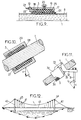
- Figures 10 and 11 show embodiments in which the effort of longitudinal compression applied to the deformable structure results from a transformation of the longitudinal component of the load C exerted on the cable by the element to be fixed.
- the cable 1 is in the inclined position, and the load C is directed vertically.
- an annular stop 27 is fixed on the cable 1, by exerting a moderate tightening on the latter.
- the lower end of the deformable structure 3 is supported on this stop 27, and its upper end on an inner rim 28 integral with the housing 29.
- the load C transmitted to the housing 29 by the element to be fixed has a longitudinal component C L directed from the upper end to the lower end of the deformable structure. This component C L urges the flange 28 towards the deformable structure 3, which is compressed between the stop 27 and the flange 28. It should be noted that the slip resistance offered by the device is greater than that provided for the single stop 27 attached to the cable.
- the element to be fixed 31 is attached to a lever 32 articulated at its opposite end on a support 33 secured to the housing 34, the axis of articulation A being horizontal and perpendicular to the cable 1.
- a intermediate zone of the lever 32 is applied against a support piece 35 penetrating into the housing 34 where it exerts the longitudinal compression force at one end of the deformable structure, the opposite end of which abuts against a rim 36 integral with the housing 34 , as shown by the tearing of the case in the figure.
- This arrangement transmits the longitudinal component C L of the load to the deformable structure 3, with an amplification depending on the dimensions of the lever 32.
- FIG 12 schematically illustrates a suspension bridge having one or more several carrying cables 1 equipped with fixing devices according to the invention.
- the carrying cable 1 is anchored at both ends of the bridge, and it passes over pylons 40.
- Lines 41 are hung on the carrying cable for support the deck 42 of the bridge.
- the lines 41 are fixed to the carrying cable at their upper ends which are attached to housings 43 forming part fixing devices of the type described above. These devices prevent the vertical lines 41 from sliding along the cable under the effect of the component parallel to the cable of the load exerted vertically by the deck 42.
- the building element connected to the housing 43 can be directly a portion secured to the deck.
- the carrying cable 1 is deflected at the top of the pylons 40, where the tensile force may be asymmetrical. We can therefore be led to block the cable to prevent it from sliding relative to the pylons. For that, we install at the top of the pylons 40 of the boxes 44 which surround the cable 1 to block this with respect to the pylons as previously described.
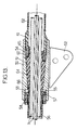
- the housing 50 In the fixing device shown in FIG. 13, the housing 50, generally cylindrical in shape, is crossed by an axial frustoconical orifice 51. In the case of a hanger attachment collar, a rib 52 is welded outside the cylindrical housing 50 to receive a yoke fixed at the end top of the hanger.
- the cylindrical housing 50 further comprises two internal threads 53, 54 on either side of the frustoconical orifice 51.
- the thread 53 is formed at the periphery of a cylindrical recess 55 formed above the orifice frustoconical 51 (to the left of FIG. 13).
- This orifice 55 receives the end lower of a sheath element 56, provided with a radial shoulder 57.
- a nut 58 externally threaded bears against the shoulder 57 and cooperates with the thread 53 to connect the sheath element 56 to the housing 50.
- the thread 54 is formed at the periphery of another recess cylindrical 60 formed below the frustoconical orifice 61.
- This thread 54 receives a complementary external thread 61 formed at one end upper of another section of sheath 62 in order to connect this section of sheath 62 in case 50.
- the sheath sections 56, 62 extend between two consecutive collars on the carrying cable.
- the sheath sections 62 connected on the sides lower housings 50 have a diameter slightly greater than that of sheath sections 56 connected on the upper sides of the housings.
- These two sheath sections 56, 62 overlap over a certain length in the interval between two collars. This telescopic overlap allows shorten the sheath between the collars to facilitate mounting, and allow differential expansions between materials.
- the frustoconical orifice 51 of the housing 50 receives a frustoconical jaw complementary 64 which performs the wedging between the cable and the housing.
- the jaw 64 can be made up of several sectors separate angles, for example three in number.
- the nut 65 is screwed into the recess 60 in order to push the jaw 64 towards the end upper of smaller diameter of the frustoconical orifice 51.
- the jaw 64 is thus finds it compressed longitudinally between its frustoconical interface with the housing 50 and its rear end urged by the nut 65.
- the fixing device according to FIG. 13 is still in safety condition, due to self-wedging operation including in cases where there may be a slight upward movement of the hanging.
- the assembly is also self-wedging in case of overload accidental on the hanger.
- the force transmission nut 65 is tightened by means of a tool suitable, such as a hook wrench, to a predefined torque to ensure sufficient tightening between cable 1 and housing 50.
- the tightening efficiency can be increased by filling gaps between strands with inserts curvilinear plastic (see EP-A-0 789 110).
- inserts curvilinear plastic see EP-A-0 789 110.
- plastic for example HDPE or polyamide, and the volume it occupies is confined.
- nut 65 has a configuration suitable also for preventing the creep of the material of the jaw.
Landscapes
- Architecture (AREA)
- Civil Engineering (AREA)
- Structural Engineering (AREA)
- Engineering & Computer Science (AREA)
- Bridges Or Land Bridges (AREA)
- Installation Of Indoor Wiring (AREA)
- Flexible Shafts (AREA)
- Mutual Connection Of Rods And Tubes (AREA)
- Laying Of Electric Cables Or Lines Outside (AREA)
- Suspension Of Electric Lines Or Cables (AREA)
- Joining Of Building Structures In Genera (AREA)
- Details Of Connecting Devices For Male And Female Coupling (AREA)
- Ropes Or Cables (AREA)
- Multi-Conductor Connections (AREA)
- Supports For Pipes And Cables (AREA)
Priority Applications (19)
| Application Number | Priority Date | Filing Date | Title |
|---|---|---|---|
| BR9916832-4A BR9916832A (pt) | 1998-12-24 | 1999-12-20 | Dispositivo e processo de fixação entre um elemento de construção e um cabo de estrutura |
| AU17835/00A AU1783500A (en) | 1998-12-24 | 1999-12-20 | Fixing device and method between a structural element and a suspension cable |
| AT02026161T ATE426064T1 (de) | 1998-12-24 | 1999-12-20 | Anordnung und verfahren zum verbinden eines bauelements und einer kabelstruktur und hangebrucke mit solchen anordnungen |
| CA002356819A CA2356819C (fr) | 1998-12-24 | 1999-12-20 | Dispositif et procede de fixation entre un element de construction et un cable de structure |
| DK99961108T DK1144760T3 (da) | 1998-12-24 | 1999-12-20 | Indretning og fremgangsmåde til forbindelse af et konstruktionselement og et strukturkabel |
| KR10-2001-7008151A KR100519495B1 (ko) | 1998-12-24 | 1999-12-20 | 구조 부재와 현수 케이블 사이의 고정 장치 및 고정 방법 |
| EP02026161A EP1284324B1 (de) | 1998-12-24 | 1999-12-20 | Anordnung und Verfahren zum Verbinden eines Bauelements und einer Kabelstruktur und Hängebrücke mit solchen Anordnungen |
| AT99961108T ATE234968T1 (de) | 1998-12-24 | 1999-12-20 | Anordnung und verfahren zum verbinden eines bauelements und einer kabelstruktur |
| PT99961108T PT1144760E (pt) | 1998-12-24 | 1999-12-20 | Dispositivo e processo de fixacao entre um elemento de construcao e um cabo estrutural |
| DE69906145T DE69906145T2 (de) | 1998-12-24 | 1999-12-20 | Anordnung und verfahren zum verbinden eines bauelements und einer kabelstruktur |
| DE69940615T DE69940615D1 (de) | 1998-12-24 | 1999-12-20 | Anordnung und Verfahren zum Verbinden eines Bauelements und einer Kabelstruktur und Hängebrücke mit solchen Anordnungen |
| PCT/FR1999/003200 WO2000039401A1 (fr) | 1998-12-24 | 1999-12-20 | Dispositif et procede de fixation entre un element de construction et un cable de structure |
| JP2000591281A JP3730513B2 (ja) | 1998-12-24 | 1999-12-20 | 建設要素および構造ケーブルを固定する装置および方法 |
| EP99961108A EP1144760B1 (de) | 1998-12-24 | 1999-12-20 | Anordnung und verfahren zum verbinden eines bauelements und einer kabelstruktur |
| DK02026161T DK1284324T3 (da) | 1998-12-24 | 1999-12-20 | Indretning og fremgangsmåde til tilvejebringelse af en forbindelse mellem et byggelement og en kabelstruktur og hængebro med sådanne indretninger |
| ES99961108T ES2194539T3 (es) | 1998-12-24 | 1999-12-20 | Dispositivo y procedimiento de fijacion entre un elemento de construccion y un cable de estructura. |
| PT02026161T PT1284324E (pt) | 1998-12-24 | 1999-12-20 | Dispositivo e processo para fixação entre um elemento de construção e um cabo estrutural, e ponte suspensa incorporando dispositivo destes |
| US09/869,225 US6523207B1 (en) | 1998-12-24 | 1999-12-20 | Fixing device and method between a structural element and a suspension cable |
| US10/317,294 US6715176B2 (en) | 1998-12-24 | 2002-12-12 | Device and method for fixing together a construction element and structural cable |
Applications Claiming Priority (2)
| Application Number | Priority Date | Filing Date | Title |
|---|---|---|---|
| FR9816448 | 1998-12-24 | ||
| FR9816448 | 1998-12-24 |
Publications (1)
| Publication Number | Publication Date |
|---|---|
| EP1013830A1 true EP1013830A1 (de) | 2000-06-28 |
Family
ID=9534512
Family Applications (3)
| Application Number | Title | Priority Date | Filing Date |
|---|---|---|---|
| EP99401563A Withdrawn EP1013830A1 (de) | 1998-12-24 | 1999-06-23 | Anordnung und Verfahren zum Verbinden eines Bauelements und einer Kabelstruktur und Hängebrücke mit solchen Anordnungen |
| EP99961108A Expired - Lifetime EP1144760B1 (de) | 1998-12-24 | 1999-12-20 | Anordnung und verfahren zum verbinden eines bauelements und einer kabelstruktur |
| EP02026161A Expired - Lifetime EP1284324B1 (de) | 1998-12-24 | 1999-12-20 | Anordnung und Verfahren zum Verbinden eines Bauelements und einer Kabelstruktur und Hängebrücke mit solchen Anordnungen |
Family Applications After (2)
| Application Number | Title | Priority Date | Filing Date |
|---|---|---|---|
| EP99961108A Expired - Lifetime EP1144760B1 (de) | 1998-12-24 | 1999-12-20 | Anordnung und verfahren zum verbinden eines bauelements und einer kabelstruktur |
| EP02026161A Expired - Lifetime EP1284324B1 (de) | 1998-12-24 | 1999-12-20 | Anordnung und Verfahren zum Verbinden eines Bauelements und einer Kabelstruktur und Hängebrücke mit solchen Anordnungen |
Country Status (13)
| Country | Link |
|---|---|
| US (2) | US6523207B1 (de) |
| EP (3) | EP1013830A1 (de) |
| JP (1) | JP3730513B2 (de) |
| KR (1) | KR100519495B1 (de) |
| AT (2) | ATE234968T1 (de) |
| AU (1) | AU1783500A (de) |
| BR (1) | BR9916832A (de) |
| CA (1) | CA2356819C (de) |
| DE (2) | DE69940615D1 (de) |
| DK (2) | DK1144760T3 (de) |
| ES (2) | ES2324397T3 (de) |
| PT (2) | PT1284324E (de) |
| WO (1) | WO2000039401A1 (de) |
Cited By (4)
| Publication number | Priority date | Publication date | Assignee | Title |
|---|---|---|---|---|
| US6560807B1 (en) * | 1999-09-15 | 2003-05-13 | Freyssinet International (Stup) | Cable with parallel wires for building work structure, anchoring for said cable, and anchoring method |
| US7631384B2 (en) * | 2003-11-12 | 2009-12-15 | Freyssinet | Device for damping vibrations of a guy-cable array for an engineering construction and corresponding damping method |
| CN101787676B (zh) * | 2010-02-08 | 2011-12-07 | 法尔胜集团有限公司 | 缆索内置光纤光栅应变传感器的安装方法 |
| CN103078207A (zh) * | 2012-12-28 | 2013-05-01 | 泰州市航宇电器有限公司 | 一种具有螺钉防脱屏蔽线夹机构的圆形连接器插头 |
Families Citing this family (32)
| Publication number | Priority date | Publication date | Assignee | Title |
|---|---|---|---|---|
| EP1013830A1 (de) * | 1998-12-24 | 2000-06-28 | Freyssinet International Stup | Anordnung und Verfahren zum Verbinden eines Bauelements und einer Kabelstruktur und Hängebrücke mit solchen Anordnungen |
| FR2825389B1 (fr) * | 2001-05-29 | 2008-02-01 | Baudin Chateauneuf | Ouvrage comportant une charge suspendue a un cable porteur entoure d'une gaine extrudee |
| EP1411170A1 (de) * | 2002-10-15 | 2004-04-21 | Fatzer Ag | Zugelement, insbesondere zur Aufhängung von Bauteilen, sowie ein Verfahren zu dessen Herstellung |
| FR2849070B1 (fr) * | 2002-12-18 | 2005-03-04 | Freyssinet Int Stup | Procede de montage d'un hauban |
| ATE458089T1 (de) * | 2003-03-24 | 2010-03-15 | Freyssinet | Kabel für bauwerke |
| ES2301805T3 (es) * | 2003-06-02 | 2008-07-01 | Freyssinet | Metodo para anclar cables de hilos paralelos. |
| RU2247190C1 (ru) * | 2003-07-09 | 2005-02-27 | Ситников Сергей Львович | Устройство усиления моста |
| RU2266996C2 (ru) * | 2004-03-09 | 2005-12-27 | Шестериков Владимир Иванович | Устройство усиления моста |
| US7195417B2 (en) * | 2004-07-21 | 2007-03-27 | Honeywell International, Inc. | Composite tie rod |
| FR2883376B1 (fr) * | 2005-03-17 | 2007-06-15 | Fressinet Internat Stup | Procede de detection de rupture au sein d'une structure et systeme pour la mise en oeuvre du procede |
| US20060241197A1 (en) * | 2005-04-25 | 2006-10-26 | Velsicol Chemical Corporation | Plasticizer compositions for flexible closed cell foams |
| US7415746B2 (en) * | 2005-12-01 | 2008-08-26 | Sc Solutions | Method for constructing a self anchored suspension bridge |
| ES2317743B1 (es) * | 2006-06-30 | 2010-02-05 | Tecnicas Del Pretensado Y Servicios Auxiliares, S.L. | Sistema de estanqueidad para anclajes en puentes atirantados. |
| KR100816059B1 (ko) * | 2007-03-27 | 2008-03-24 | 케이블텍 주식회사 | 케이블 댐퍼 |
| KR100930114B1 (ko) * | 2009-05-22 | 2009-12-07 | 케이블텍 주식회사 | 케이블 간격 유지 장치 |
| KR101066997B1 (ko) | 2009-05-26 | 2011-09-22 | 주식회사 두배시스템 | 신축성 시그널 케이블 어셈블리 및 이를 구비한 지반 조사용 로드 어셈블리 |
| FR2968681B1 (fr) * | 2010-12-08 | 2015-05-29 | Soletanche Freyssinet | Dispositif de deviation d'un cable de structure tel qu'un hauban, et ouvrage ainsi equipe |
| FR2973818B1 (fr) * | 2011-04-07 | 2017-06-02 | Soletanche Freyssinet | Procede et dispositif de protection de l'extremite d'un cable ancre |
| US20120260590A1 (en) | 2011-04-12 | 2012-10-18 | Lambert Walter L | Parallel Wire Cable |
| US8474219B2 (en) | 2011-07-13 | 2013-07-02 | Ultimate Strength Cable, LLC | Stay cable for structures |
| GB2514621B (en) * | 2013-05-31 | 2020-04-15 | Vsl Int Ag | Cable anchorage |
| CN105507148A (zh) * | 2014-09-26 | 2016-04-20 | 上海建科预应力技术工程有限公司 | 一种悬索桥的索夹与吊杆的连接结构 |
| CH710269A2 (de) * | 2014-10-17 | 2016-04-29 | Fatzer Ag Drahtseilfabrik | Vorspannlitze, insbesondere für statische Verbauungen. |
| CN104594179B (zh) * | 2015-02-06 | 2016-06-08 | 中建三局集团有限公司 | 一种纵向双吊杆自锚式叠合梁悬索桥吊杆张力的控制方法 |
| CN105421231B (zh) * | 2015-12-25 | 2017-03-15 | 招商局重庆交通科研设计院有限公司 | 桥梁用cfrp筋拉索群锚锚具及制作工艺 |
| CN105972015B (zh) * | 2016-07-29 | 2017-12-29 | 温岭市锦鹏日用品有限公司 | 一种托架承载锁定组件 |
| CN106015857B (zh) * | 2016-07-29 | 2017-12-26 | 浦江升广科技有限责任公司 | 一种安全托架承载锁定组件 |
| US11248676B2 (en) * | 2018-06-07 | 2022-02-15 | Preformed Line Products Co. | Vibration damper |
| CN112411376B (zh) * | 2020-12-07 | 2022-09-30 | 柳州市邱姆预应力机械有限公司 | 拉索抗滑装置及其安装方法 |
| CN113718664B (zh) * | 2021-09-15 | 2023-03-03 | 中铁一局集团有限公司 | 一种不等跨钢箱梁斜拉桥跨营业线盖梁顶转体施工方法 |
| CN114941288B (zh) * | 2022-03-16 | 2023-05-09 | 中铁九桥工程有限公司 | 一种悬索桥散索套施工方法 |
| CN119800847B (zh) * | 2025-01-08 | 2025-10-17 | 中交第二航务工程局有限公司 | 一种非对称索力张拉快速固定装置及使用方法 |
Citations (3)
| Publication number | Priority date | Publication date | Assignee | Title |
|---|---|---|---|---|
| DE869977C (de) * | 1942-03-13 | 1953-03-09 | Gutehoffnungshuette Oberhausen | Schelle, insbesondere zum Verbinden der Haengeseile mit den Tragseilen bei Haengebruecken od. dgl. |
| EP0789110A1 (de) * | 1996-02-06 | 1997-08-13 | Freyssinet International (Stup) | Aufhängevorrichtung für Bauwerke und Verfahren zum Herstellen |
| EP0855471A1 (de) * | 1995-09-26 | 1998-07-29 | Freyssinet International (Stup) | Individuell geschützte Litze für hängende Bauwerke, Bauwerke mit diesen Litzen und Herstellungsverfahren |
Family Cites Families (17)
| Publication number | Priority date | Publication date | Assignee | Title |
|---|---|---|---|---|
| US511605A (en) * | 1893-12-26 | Frederick | ||
| US440490A (en) * | 1890-11-11 | Construction of bridges | ||
| US1293383A (en) * | 1917-07-20 | 1919-02-04 | Warren S Eaton | Cable-coupling. |
| AT126831B (de) * | 1929-10-17 | 1932-02-10 | Felten & Guilleaume Carlswerk | Verfahren und Vorrichtung zur Herabsetzung der Dehnung bei Drahtseilen. |
| US1811154A (en) * | 1930-01-10 | 1931-06-23 | Williamsport Wire Rope Company | Fitting for light duty suspension hangers |
| US2057328A (en) * | 1933-11-16 | 1936-10-13 | Cordova Joaquin Pedrero | Sectional cable suspension assembly |
| US2011168A (en) * | 1934-05-01 | 1935-08-13 | Roeblings John A Sons Co | Suspension bridge |
| US2748407A (en) * | 1951-12-26 | 1956-06-05 | Bethlehem Steel Corp | Wedge fillers for suspension bridge cables |
| US3531811A (en) * | 1968-10-15 | 1970-10-06 | Bethlehem Steel Corp | Method for erecting parallel-wire bridge strand |
| DE3114532C1 (de) * | 1981-04-10 | 1982-11-04 | Willy Habegger AG, 3600 Thun | Haengebruecke |
| DE3138819C2 (de) * | 1981-09-30 | 1986-10-23 | Dyckerhoff & Widmann AG, 8000 München | Verfahren zur Montage eines zwischen seinen Verankerungsstellen frei gespannt verlaufenden Zuggliedes, insbesondere eines Schrägkabels für eine Schrägkabelbrücke |
| DE3434620A1 (de) * | 1984-09-21 | 1986-04-03 | Dyckerhoff & Widmann AG, 8000 München | Abstuetzung eines freien zugglieds, vorzugsweise eines schraegseils einer schraegseilbruecke |
| DE29506476U1 (de) * | 1995-04-15 | 1996-08-14 | Dyckerhoff & Widmann AG, 81902 München | Vorrichtung zur Verwendung beim Einführen der einzelnen Zugelemente eines frei gespannten Zugglieds |
| US6138309A (en) * | 1997-12-10 | 2000-10-31 | Board Of Regents Of University Of Nebraska | Tension members for erecting structures |
| FR2780127B1 (fr) * | 1998-06-19 | 2000-09-08 | Freyssinet Int Stup | Procede et dispositif d'accrochage d'un element transmetteur de charge sur un cable, et pont suspendu comportant de tels dispositifs |
| EP1013830A1 (de) * | 1998-12-24 | 2000-06-28 | Freyssinet International Stup | Anordnung und Verfahren zum Verbinden eines Bauelements und einer Kabelstruktur und Hängebrücke mit solchen Anordnungen |
| US6292967B1 (en) * | 1999-09-14 | 2001-09-25 | Construction Technology Laboratories, Inc. | TMD-damped stay cable and method and TMD |
-
1999
- 1999-06-23 EP EP99401563A patent/EP1013830A1/de not_active Withdrawn
- 1999-12-20 WO PCT/FR1999/003200 patent/WO2000039401A1/fr not_active Ceased
- 1999-12-20 KR KR10-2001-7008151A patent/KR100519495B1/ko not_active Expired - Fee Related
- 1999-12-20 DK DK99961108T patent/DK1144760T3/da active
- 1999-12-20 JP JP2000591281A patent/JP3730513B2/ja not_active Expired - Fee Related
- 1999-12-20 DE DE69940615T patent/DE69940615D1/de not_active Expired - Lifetime
- 1999-12-20 US US09/869,225 patent/US6523207B1/en not_active Expired - Lifetime
- 1999-12-20 ES ES02026161T patent/ES2324397T3/es not_active Expired - Lifetime
- 1999-12-20 DE DE69906145T patent/DE69906145T2/de not_active Expired - Lifetime
- 1999-12-20 PT PT02026161T patent/PT1284324E/pt unknown
- 1999-12-20 DK DK02026161T patent/DK1284324T3/da active
- 1999-12-20 EP EP99961108A patent/EP1144760B1/de not_active Expired - Lifetime
- 1999-12-20 AT AT99961108T patent/ATE234968T1/de not_active IP Right Cessation
- 1999-12-20 AT AT02026161T patent/ATE426064T1/de not_active IP Right Cessation
- 1999-12-20 PT PT99961108T patent/PT1144760E/pt unknown
- 1999-12-20 ES ES99961108T patent/ES2194539T3/es not_active Expired - Lifetime
- 1999-12-20 EP EP02026161A patent/EP1284324B1/de not_active Expired - Lifetime
- 1999-12-20 BR BR9916832-4A patent/BR9916832A/pt not_active IP Right Cessation
- 1999-12-20 AU AU17835/00A patent/AU1783500A/en not_active Abandoned
- 1999-12-20 CA CA002356819A patent/CA2356819C/fr not_active Expired - Fee Related
-
2002
- 2002-12-12 US US10/317,294 patent/US6715176B2/en not_active Expired - Fee Related
Patent Citations (3)
| Publication number | Priority date | Publication date | Assignee | Title |
|---|---|---|---|---|
| DE869977C (de) * | 1942-03-13 | 1953-03-09 | Gutehoffnungshuette Oberhausen | Schelle, insbesondere zum Verbinden der Haengeseile mit den Tragseilen bei Haengebruecken od. dgl. |
| EP0855471A1 (de) * | 1995-09-26 | 1998-07-29 | Freyssinet International (Stup) | Individuell geschützte Litze für hängende Bauwerke, Bauwerke mit diesen Litzen und Herstellungsverfahren |
| EP0789110A1 (de) * | 1996-02-06 | 1997-08-13 | Freyssinet International (Stup) | Aufhängevorrichtung für Bauwerke und Verfahren zum Herstellen |
Cited By (5)
| Publication number | Priority date | Publication date | Assignee | Title |
|---|---|---|---|---|
| US6560807B1 (en) * | 1999-09-15 | 2003-05-13 | Freyssinet International (Stup) | Cable with parallel wires for building work structure, anchoring for said cable, and anchoring method |
| US7631384B2 (en) * | 2003-11-12 | 2009-12-15 | Freyssinet | Device for damping vibrations of a guy-cable array for an engineering construction and corresponding damping method |
| CN101787676B (zh) * | 2010-02-08 | 2011-12-07 | 法尔胜集团有限公司 | 缆索内置光纤光栅应变传感器的安装方法 |
| CN103078207A (zh) * | 2012-12-28 | 2013-05-01 | 泰州市航宇电器有限公司 | 一种具有螺钉防脱屏蔽线夹机构的圆形连接器插头 |
| CN103078207B (zh) * | 2012-12-28 | 2015-04-22 | 泰州市航宇电器有限公司 | 一种具有螺钉防脱屏蔽线夹机构的圆形连接器插头 |
Also Published As
| Publication number | Publication date |
|---|---|
| EP1144760B1 (de) | 2003-03-19 |
| DK1284324T3 (da) | 2009-07-20 |
| PT1284324E (pt) | 2009-07-14 |
| EP1284324A3 (de) | 2003-02-26 |
| JP3730513B2 (ja) | 2006-01-05 |
| DE69906145D1 (de) | 2003-04-24 |
| EP1284324B1 (de) | 2009-03-18 |
| WO2000039401A1 (fr) | 2000-07-06 |
| BR9916832A (pt) | 2001-09-25 |
| CA2356819A1 (fr) | 2000-07-06 |
| US20030086755A1 (en) | 2003-05-08 |
| KR20010086155A (ko) | 2001-09-08 |
| US6715176B2 (en) | 2004-04-06 |
| EP1144760A1 (de) | 2001-10-17 |
| KR100519495B1 (ko) | 2005-10-07 |
| DE69940615D1 (de) | 2009-04-30 |
| JP2002533595A (ja) | 2002-10-08 |
| DE69906145T2 (de) | 2004-02-05 |
| ATE234968T1 (de) | 2003-04-15 |
| AU1783500A (en) | 2000-07-31 |
| PT1144760E (pt) | 2003-08-29 |
| DK1144760T3 (da) | 2003-07-21 |
| US6523207B1 (en) | 2003-02-25 |
| ES2324397T3 (es) | 2009-08-06 |
| EP1284324A2 (de) | 2003-02-19 |
| ATE426064T1 (de) | 2009-04-15 |
| ES2194539T3 (es) | 2003-11-16 |
| CA2356819C (fr) | 2006-12-19 |
Similar Documents
| Publication | Publication Date | Title |
|---|---|---|
| EP1144760B1 (de) | Anordnung und verfahren zum verbinden eines bauelements und einer kabelstruktur | |
| EP1131512B1 (de) | Verankerungsvorrichtung zum befestigen eines strukturkabels an einen bauteil | |
| EP1181422B1 (de) | Vorrichtung zur verankerung einer kabelstruktur | |
| EP1003983B1 (de) | Verfahren und vorrichtung zur befestigung eines lastübertragenden elements an einem seil, und solche vorrichtungen aufweisende hängebrücke | |
| EP0323285B2 (de) | Schrägseile und deren Verankerung | |
| BE1015078A5 (fr) | Methode de suspension d'outillage. | |
| FR2546215A1 (fr) | Traversee pour le passage de conduits tels que des cables, tuyaux, etc. par une ouverture dans le mur et dispositif pour la realisation d'une surface interieure pour une telle traversee dans un mur en beton | |
| EP1131492B1 (de) | Kabelverbindungssystem an einem bauwerk | |
| WO2001068986A1 (fr) | Ancrage reglable pour cable portant une structure de genie civil | |
| CA3071452A1 (fr) | Ensemble ameliore comprenant un cable de structure et une selle | |
| EP0789110B1 (de) | Aufhängevorrichtung für Bauwerke und Verfahren zum Herstellen | |
| FR2644819A1 (fr) | Procede de fixation de la tete d'un dispositif d'ancrage | |
| FR2791373A1 (fr) | Dispositif pour fixer un cable de structure a un element de construction | |
| EP1561049A1 (de) | Vorrichtung zur verankerung von beliebigen elememten an einer wand | |
| FR2708017A1 (fr) | Perfectionnements aux mors tronconiques d'ancrage pour câbles et à leurs procédés de mise en Óoeuvre. | |
| EP0465303A1 (de) | Verbesserungen an Schrägseilbrücken und insbesondere an deren Seilen und Pfeilern | |
| FR2724405A3 (fr) | Pylone pourvu d'un manchon conique interieur | |
| EP0221817A2 (de) | Befestigungsvorrichtung zum Verbinden von Riemen, solch eine Vorrichtung verwendendes Verbindungsverfahren und nach diesem Verfahren verbundene Riemen | |
| FR2484584A1 (fr) | Dispositif de serrage pour cable de haubanage a plusieurs torons | |
| FR2707435A1 (fr) | Dispositif d'ancrage pour câble aérien autoporté. | |
| FR2922978A1 (fr) | Serre cable anti-torsion | |
| FR2624941A1 (fr) | Embout pour l'attache de cable ou corde en fibres synthetiques et procede pour sa fabrication | |
| FR3055644A1 (fr) | Dispositif de fixation d'un organe d'ancrage de securite sur une couverture d'une toiture d'un batiment | |
| FR2730511A1 (fr) | Dispositif d'ancrage mutuel de deux parois | |
| FR2571556A1 (fr) | Dispositif pour hisser un cable du sol a son point d'ancrage sur un pylone |
Legal Events
| Date | Code | Title | Description |
|---|---|---|---|
| PUAI | Public reference made under article 153(3) epc to a published international application that has entered the european phase |
Free format text: ORIGINAL CODE: 0009012 |
|
| AK | Designated contracting states |
Kind code of ref document: A1 Designated state(s): DE |
|
| AX | Request for extension of the european patent |
Free format text: AL;LT;LV;MK;RO;SI |
|
| AKX | Designation fees paid |
Free format text: DE |
|
| STAA | Information on the status of an ep patent application or granted ep patent |
Free format text: STATUS: THE APPLICATION IS DEEMED TO BE WITHDRAWN |
|
| 18D | Application deemed to be withdrawn |
Effective date: 20001229 |