EP1013905A1 - Agencement d'un catalyseur à un moteur à combustion interne - Google Patents
Agencement d'un catalyseur à un moteur à combustion interne Download PDFInfo
- Publication number
- EP1013905A1 EP1013905A1 EP99123945A EP99123945A EP1013905A1 EP 1013905 A1 EP1013905 A1 EP 1013905A1 EP 99123945 A EP99123945 A EP 99123945A EP 99123945 A EP99123945 A EP 99123945A EP 1013905 A1 EP1013905 A1 EP 1013905A1
- Authority
- EP
- European Patent Office
- Prior art keywords
- catalyst
- housing
- engine
- arrangement according
- catalyst housing
- Prior art date
- Legal status (The legal status is an assumption and is not a legal conclusion. Google has not performed a legal analysis and makes no representation as to the accuracy of the status listed.)
- Granted
Links
Images

Classifications
-
- F—MECHANICAL ENGINEERING; LIGHTING; HEATING; WEAPONS; BLASTING
- F01—MACHINES OR ENGINES IN GENERAL; ENGINE PLANTS IN GENERAL; STEAM ENGINES
- F01N—GAS-FLOW SILENCERS OR EXHAUST APPARATUS FOR MACHINES OR ENGINES IN GENERAL; GAS-FLOW SILENCERS OR EXHAUST APPARATUS FOR INTERNAL-COMBUSTION ENGINES
- F01N13/00—Exhaust or silencing apparatus characterised by constructional features
- F01N13/18—Construction facilitating manufacture, assembly, or disassembly
- F01N13/1805—Fixing exhaust manifolds, exhaust pipes or pipe sections to each other, to engine or to vehicle body
- F01N13/1811—Fixing exhaust manifolds, exhaust pipes or pipe sections to each other, to engine or to vehicle body with means permitting relative movement, e.g. compensation of thermal expansion or vibration
- F01N13/1816—Fixing exhaust manifolds, exhaust pipes or pipe sections to each other, to engine or to vehicle body with means permitting relative movement, e.g. compensation of thermal expansion or vibration the pipe sections being joined together by flexible tubular elements only, e.g. using bellows or strip-wound pipes
-
- B—PERFORMING OPERATIONS; TRANSPORTING
- B60—VEHICLES IN GENERAL
- B60K—ARRANGEMENT OR MOUNTING OF PROPULSION UNITS OR OF TRANSMISSIONS IN VEHICLES; ARRANGEMENT OR MOUNTING OF PLURAL DIVERSE PRIME-MOVERS IN VEHICLES; AUXILIARY DRIVES FOR VEHICLES; INSTRUMENTATION OR DASHBOARDS FOR VEHICLES; ARRANGEMENTS IN CONNECTION WITH COOLING, AIR INTAKE, GAS EXHAUST OR FUEL SUPPLY OF PROPULSION UNITS IN VEHICLES
- B60K13/00—Arrangement in connection with combustion air intake or gas exhaust of propulsion units
- B60K13/04—Arrangement in connection with combustion air intake or gas exhaust of propulsion units concerning exhaust
-
- F—MECHANICAL ENGINEERING; LIGHTING; HEATING; WEAPONS; BLASTING
- F01—MACHINES OR ENGINES IN GENERAL; ENGINE PLANTS IN GENERAL; STEAM ENGINES
- F01N—GAS-FLOW SILENCERS OR EXHAUST APPARATUS FOR MACHINES OR ENGINES IN GENERAL; GAS-FLOW SILENCERS OR EXHAUST APPARATUS FOR INTERNAL-COMBUSTION ENGINES
- F01N13/00—Exhaust or silencing apparatus characterised by constructional features
-
- F—MECHANICAL ENGINEERING; LIGHTING; HEATING; WEAPONS; BLASTING
- F01—MACHINES OR ENGINES IN GENERAL; ENGINE PLANTS IN GENERAL; STEAM ENGINES
- F01N—GAS-FLOW SILENCERS OR EXHAUST APPARATUS FOR MACHINES OR ENGINES IN GENERAL; GAS-FLOW SILENCERS OR EXHAUST APPARATUS FOR INTERNAL-COMBUSTION ENGINES
- F01N13/00—Exhaust or silencing apparatus characterised by constructional features
- F01N13/009—Exhaust or silencing apparatus characterised by constructional features having two or more separate purifying devices arranged in series
-
- F—MECHANICAL ENGINEERING; LIGHTING; HEATING; WEAPONS; BLASTING
- F01—MACHINES OR ENGINES IN GENERAL; ENGINE PLANTS IN GENERAL; STEAM ENGINES
- F01N—GAS-FLOW SILENCERS OR EXHAUST APPARATUS FOR MACHINES OR ENGINES IN GENERAL; GAS-FLOW SILENCERS OR EXHAUST APPARATUS FOR INTERNAL-COMBUSTION ENGINES
- F01N13/00—Exhaust or silencing apparatus characterised by constructional features
- F01N13/011—Exhaust or silencing apparatus characterised by constructional features having two or more purifying devices arranged in parallel
-
- F—MECHANICAL ENGINEERING; LIGHTING; HEATING; WEAPONS; BLASTING
- F01—MACHINES OR ENGINES IN GENERAL; ENGINE PLANTS IN GENERAL; STEAM ENGINES
- F01N—GAS-FLOW SILENCERS OR EXHAUST APPARATUS FOR MACHINES OR ENGINES IN GENERAL; GAS-FLOW SILENCERS OR EXHAUST APPARATUS FOR INTERNAL-COMBUSTION ENGINES
- F01N13/00—Exhaust or silencing apparatus characterised by constructional features
- F01N13/08—Other arrangements or adaptations of exhaust conduits
- F01N13/10—Other arrangements or adaptations of exhaust conduits of exhaust manifolds
-
- F—MECHANICAL ENGINEERING; LIGHTING; HEATING; WEAPONS; BLASTING
- F01—MACHINES OR ENGINES IN GENERAL; ENGINE PLANTS IN GENERAL; STEAM ENGINES
- F01N—GAS-FLOW SILENCERS OR EXHAUST APPARATUS FOR MACHINES OR ENGINES IN GENERAL; GAS-FLOW SILENCERS OR EXHAUST APPARATUS FOR INTERNAL-COMBUSTION ENGINES
- F01N3/00—Exhaust or silencing apparatus having means for purifying, rendering innocuous, or otherwise treating exhaust
- F01N3/08—Exhaust or silencing apparatus having means for purifying, rendering innocuous, or otherwise treating exhaust for rendering innocuous
- F01N3/10—Exhaust or silencing apparatus having means for purifying, rendering innocuous, or otherwise treating exhaust for rendering innocuous by thermal or catalytic conversion of noxious components of exhaust
- F01N3/24—Exhaust or silencing apparatus having means for purifying, rendering innocuous, or otherwise treating exhaust for rendering innocuous by thermal or catalytic conversion of noxious components of exhaust characterised by constructional aspects of converting apparatus
- F01N3/28—Construction of catalytic reactors
-
- F—MECHANICAL ENGINEERING; LIGHTING; HEATING; WEAPONS; BLASTING
- F01—MACHINES OR ENGINES IN GENERAL; ENGINE PLANTS IN GENERAL; STEAM ENGINES
- F01N—GAS-FLOW SILENCERS OR EXHAUST APPARATUS FOR MACHINES OR ENGINES IN GENERAL; GAS-FLOW SILENCERS OR EXHAUST APPARATUS FOR INTERNAL-COMBUSTION ENGINES
- F01N3/00—Exhaust or silencing apparatus having means for purifying, rendering innocuous, or otherwise treating exhaust
- F01N3/08—Exhaust or silencing apparatus having means for purifying, rendering innocuous, or otherwise treating exhaust for rendering innocuous
- F01N3/10—Exhaust or silencing apparatus having means for purifying, rendering innocuous, or otherwise treating exhaust for rendering innocuous by thermal or catalytic conversion of noxious components of exhaust
- F01N3/24—Exhaust or silencing apparatus having means for purifying, rendering innocuous, or otherwise treating exhaust for rendering innocuous by thermal or catalytic conversion of noxious components of exhaust characterised by constructional aspects of converting apparatus
- F01N3/28—Construction of catalytic reactors
- F01N3/2882—Catalytic reactors combined or associated with other devices, e.g. exhaust silencers or other exhaust purification devices
-
- F—MECHANICAL ENGINEERING; LIGHTING; HEATING; WEAPONS; BLASTING
- F01—MACHINES OR ENGINES IN GENERAL; ENGINE PLANTS IN GENERAL; STEAM ENGINES
- F01N—GAS-FLOW SILENCERS OR EXHAUST APPARATUS FOR MACHINES OR ENGINES IN GENERAL; GAS-FLOW SILENCERS OR EXHAUST APPARATUS FOR INTERNAL-COMBUSTION ENGINES
- F01N13/00—Exhaust or silencing apparatus characterised by constructional features
- F01N13/08—Other arrangements or adaptations of exhaust conduits
- F01N13/10—Other arrangements or adaptations of exhaust conduits of exhaust manifolds
- F01N13/107—More than one exhaust manifold or exhaust collector
-
- F—MECHANICAL ENGINEERING; LIGHTING; HEATING; WEAPONS; BLASTING
- F01—MACHINES OR ENGINES IN GENERAL; ENGINE PLANTS IN GENERAL; STEAM ENGINES
- F01N—GAS-FLOW SILENCERS OR EXHAUST APPARATUS FOR MACHINES OR ENGINES IN GENERAL; GAS-FLOW SILENCERS OR EXHAUST APPARATUS FOR INTERNAL-COMBUSTION ENGINES
- F01N2260/00—Exhaust treating devices having provisions not otherwise provided for
- F01N2260/10—Exhaust treating devices having provisions not otherwise provided for for avoiding stress caused by expansions or contractions due to temperature variations
-
- F—MECHANICAL ENGINEERING; LIGHTING; HEATING; WEAPONS; BLASTING
- F01—MACHINES OR ENGINES IN GENERAL; ENGINE PLANTS IN GENERAL; STEAM ENGINES
- F01N—GAS-FLOW SILENCERS OR EXHAUST APPARATUS FOR MACHINES OR ENGINES IN GENERAL; GAS-FLOW SILENCERS OR EXHAUST APPARATUS FOR INTERNAL-COMBUSTION ENGINES
- F01N2470/00—Structure or shape of exhaust gas passages, pipes or tubes
- F01N2470/16—Plurality of inlet tubes, e.g. discharging into different chambers
-
- F—MECHANICAL ENGINEERING; LIGHTING; HEATING; WEAPONS; BLASTING
- F01—MACHINES OR ENGINES IN GENERAL; ENGINE PLANTS IN GENERAL; STEAM ENGINES
- F01N—GAS-FLOW SILENCERS OR EXHAUST APPARATUS FOR MACHINES OR ENGINES IN GENERAL; GAS-FLOW SILENCERS OR EXHAUST APPARATUS FOR INTERNAL-COMBUSTION ENGINES
- F01N2470/00—Structure or shape of exhaust gas passages, pipes or tubes
- F01N2470/18—Structure or shape of exhaust gas passages, pipes or tubes the axis of inlet or outlet tubes being other than the longitudinal axis of apparatus
-
- Y—GENERAL TAGGING OF NEW TECHNOLOGICAL DEVELOPMENTS; GENERAL TAGGING OF CROSS-SECTIONAL TECHNOLOGIES SPANNING OVER SEVERAL SECTIONS OF THE IPC; TECHNICAL SUBJECTS COVERED BY FORMER USPC CROSS-REFERENCE ART COLLECTIONS [XRACs] AND DIGESTS
- Y02—TECHNOLOGIES OR APPLICATIONS FOR MITIGATION OR ADAPTATION AGAINST CLIMATE CHANGE
- Y02A—TECHNOLOGIES FOR ADAPTATION TO CLIMATE CHANGE
- Y02A50/00—TECHNOLOGIES FOR ADAPTATION TO CLIMATE CHANGE in human health protection, e.g. against extreme weather
- Y02A50/20—Air quality improvement or preservation, e.g. vehicle emission control or emission reduction by using catalytic converters
Definitions
- the present invention relates to a catalytic converter arrangement on a motor vehicle according to the preamble of claim 1.
- EP-0,809,001 provides a solution for the arrangement of engine near Catalysts known in which in each exhaust line, i.e. at each outlet of the engine a dedicated catalyst is provided. This solution is expensive to manufacture and not because of the limited volume of the catalysts when cleaning the exhaust gases effectively.
- a catalytic converter arrangement on a motor vehicle essentially has cylindrical catalyst housing, which is arranged close to the engine, and has a A plurality of leads on between the outlets of an engine of the motor vehicle and at least one inlet of the catalyst housing are arranged, the feed lines on the two end faces of the essentially cylindrical catalyst housing open, the axial extent of the catalyst housing in runs substantially parallel to the main direction of the motor, and being the sum the lengths of the supply lines are as large as possible.
- the arrangement of the catalyst close to the engine also has the advantage that the Decoupling of the subsequent exhaust system (reference number 15, in Fig. 2) from the engine vibrations by means of the flexible hose according to claim 2 is possible. This reduces the stress on the exhaust system and can make it thinner Materials are used so that the exhaust system overall in weight is reducible. Due to the elimination of the catalytic converter under the vehicle, the appropriate place an additional silencer can be attached or it can alternatively, the first silencer (front silencer) is made much larger to meet tightening external noise regulations or to To reduce noise in the interior of the vehicle. Finally, there is another advantage that the engine noise is damped directly on the engine and that the Muzzle noises as well as the secondary airborne noise emission of the exhaust system clearly is reduced.
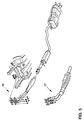
- FIG. 1 shows a first embodiment of the catalytic converter arrangement according to FIG presented present invention.
- a catalyst housing designated, which in this embodiment is essentially a cylindrical Has basic shape.
- this catalyst housing 1 there are two Catalyst elements 11, each in the left and in the right half of the Catalyst housing 1 are housed.
- the motor 4 is only indicated schematically and has in the embodiment shown four cylinders, the four outlets B, C, D and E are numbered accordingly. So are the outlets B and C of the first and the second cylinder with the right one Front side of the catalyst housing 1 connected, while the outlets D and E of the third and fourth cylinders with the left end face of the catalytic converter housing 1 are connected.
- catalytic converter housing 1 is parallel to a main direction Y of engine 4, i.e. the Direction in which the cylinders of the engine 4 are arranged one behind the other.
- a compensating element 12 is preferably provided, which a Can absorb and compensate for linear expansion of neighboring components.
- Figure 1 is approximately in the middle (but not necessarily, but between the two catalysts) on the catalyst housing 1, a derivative 9 for the cleaned Exhaust gases are provided, which in a flexible tubular exhaust pipe 6 (hereinafter Called flexible hose) opens.
- the derivative 9 runs in the radial direction arranged.
- connections 10 or 13 for one or more lambda probes can be provided in the area of the end faces of the catalyst housing 1 and / or at the outlet 9 of the catalyst housing 1.
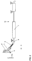
- FIG 2 is a side view of the arrangement of the engine, the catalyst and the downstream exhaust system is shown schematically.
- the (main) direction of travel A of a motor vehicle in which the arrangement is installed is oriented to the left.
- the catalytic converter housing 1 runs transversely to the direction of travel A, arranged.
- the connection between the engine 4 or its outlets 3 and the Catalyst housing 1 takes place via feed lines 2, which in the end faces of the Open the catalytic converter housing 1.
- the arrangement of the flexible hose 6 is provided after the catalytic converter housing 1, to which in turn an exhaust pipe 8 of an exhaust system 15 is connected.
- the Exhaust system 15 may include a front silencer 7 and other unspecified ones Include items.
- the flexible hose 6 is capable of slight (a few centimeters) Deviations between the position of the catalyst housing 1 and the position of the Compensate exhaust pipe 8 or exhaust system 15.
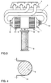
- FIG Figure 3 A further embodiment of the catalyst arrangement according to the invention is shown in FIG Figure 3 shown.
- the same components are provided with the same reference symbols there.
- This embodiment differs from that described above Embodiment in that the catalyst housing 1 is not partitioned in the middle, but is continuously trained.
- the arrangement of this catalytic converter housing 1 between an engine 4 and an exhaust system 15 is identical to the first Embodiment.
- the mode of action is also identical.
- the production of the continuous catalyst housing 1 is simpler and therefore cheaper to execute.
- FIG. 4 shows a fastening device in the form of a holder 14 shown, with which the catalyst housing 1 is attached to the engine 4.
- the Connection of the catalyst to the engine should not resonate up to 200 Hz exhibit.
- the catalytic converter arrangement according to the invention on a motor vehicle thus has preferably an essentially cylindrical catalyst housing, which is close to the engine is arranged, and also has a plurality of leads between Outlets of an engine of the motor vehicle and at least one inlet of the Catalyst housing are arranged, with the feed lines on the two end faces of the substantially cylindrical catalyst housing open, the axial Extension of the catalyst housing substantially parallel to the main direction Y of the motor runs, and the sum of the lengths of the leads as large as possible is.
- a catalytic converter is arranged close to the engine Sufficiently long supply line provided, so that problems in the torque curve can be avoided.
- the arrangement of the catalytic converter close to the engine also has the Advantage that the decoupling of the subsequent exhaust system by means of a flexible hose is possible.
Landscapes
- Engineering & Computer Science (AREA)
- Chemical & Material Sciences (AREA)
- Combustion & Propulsion (AREA)
- Mechanical Engineering (AREA)
- General Engineering & Computer Science (AREA)
- Chemical Kinetics & Catalysis (AREA)
- Health & Medical Sciences (AREA)
- Toxicology (AREA)
- Transportation (AREA)
- Exhaust Gas After Treatment (AREA)
- Exhaust Silencers (AREA)
- Electric Propulsion And Braking For Vehicles (AREA)
Applications Claiming Priority (2)
| Application Number | Priority Date | Filing Date | Title |
|---|---|---|---|
| DE19858641 | 1998-12-18 | ||
| DE19858641A DE19858641A1 (de) | 1998-12-18 | 1998-12-18 | Katalysator-Anordnung an einem Kraftfahrzeug |
Publications (2)
| Publication Number | Publication Date |
|---|---|
| EP1013905A1 true EP1013905A1 (fr) | 2000-06-28 |
| EP1013905B1 EP1013905B1 (fr) | 2002-09-04 |
Family
ID=7891685
Family Applications (1)
| Application Number | Title | Priority Date | Filing Date |
|---|---|---|---|
| EP99123945A Expired - Lifetime EP1013905B1 (fr) | 1998-12-18 | 1999-12-03 | Agencement d'un catalyseur à un moteur à combustion interne |
Country Status (3)
| Country | Link |
|---|---|
| EP (1) | EP1013905B1 (fr) |
| AT (1) | ATE223555T1 (fr) |
| DE (2) | DE19858641A1 (fr) |
Cited By (2)
| Publication number | Priority date | Publication date | Assignee | Title |
|---|---|---|---|---|
| EP1457647A1 (fr) * | 2003-03-10 | 2004-09-15 | Friedrich Boysen GmbH & Co. KG | Dispositif d'échappement d'un moteur à combustion interne |
| FR2879134A1 (fr) * | 2004-12-10 | 2006-06-16 | Renault Sas | Agencement pour le montage d'un dispositif de traitement des gaz d'echappement sur une face d'un moteur a combustion |
Families Citing this family (2)
| Publication number | Priority date | Publication date | Assignee | Title |
|---|---|---|---|---|
| DE10144015A1 (de) * | 2001-09-07 | 2003-03-27 | Bayerische Motoren Werke Ag | Abgasanlage für mehrzylindrige Verbrennungsmotoren |
| DE102013225256B4 (de) * | 2013-12-09 | 2024-06-13 | Volkswagen Aktiengesellschaft | Fahrzeug |
Citations (7)
| Publication number | Priority date | Publication date | Assignee | Title |
|---|---|---|---|---|
| JPS5920519A (ja) * | 1982-07-26 | 1984-02-02 | Yamaha Motor Co Ltd | 自動二輪車の排気浄化装置 |
| US4663934A (en) * | 1985-04-01 | 1987-05-12 | Arvin Industries, Inc. | Manifold exhaust processor |
| DE4114745A1 (de) * | 1991-05-06 | 1992-11-12 | Emitec Emissionstechnologie | Auspuffsystem mit mehrfach ausgenutzten katalysatormatrizen |
| US5265420A (en) * | 1991-05-21 | 1993-11-30 | Dr. Ing. H.C.F. Porsche Ag | Exhaust system of a multi-cylinder reciprocating engine |
| US5325666A (en) * | 1990-08-04 | 1994-07-05 | Dr. Ing. H.C.F Porsche Ag | Exhaust system of an internal-combustion engine |
| EP0807749A2 (fr) * | 1996-05-13 | 1997-11-19 | Scambia Industrial Developments Aktiengesellschaft | Dispositif d'échappement pour véhicules automobiles, ainsi que un véhicule automobile |
| JPH09317450A (ja) * | 1996-05-31 | 1997-12-09 | Suzuki Motor Corp | エンジンの触媒付排気通路 |
Family Cites Families (1)
| Publication number | Priority date | Publication date | Assignee | Title |
|---|---|---|---|---|
| DE1942227A1 (de) * | 1969-08-19 | 1971-04-08 | Aerolyt Vertriebsgesellschaft | Auspuffanlage fuer mehrzylindrige Brennkraftmaschinen,insbesondere fuer Boxermotoren |
-
1998
- 1998-12-18 DE DE19858641A patent/DE19858641A1/de not_active Withdrawn
-
1999
- 1999-12-03 DE DE59902541T patent/DE59902541D1/de not_active Expired - Fee Related
- 1999-12-03 AT AT99123945T patent/ATE223555T1/de not_active IP Right Cessation
- 1999-12-03 EP EP99123945A patent/EP1013905B1/fr not_active Expired - Lifetime
Patent Citations (7)
| Publication number | Priority date | Publication date | Assignee | Title |
|---|---|---|---|---|
| JPS5920519A (ja) * | 1982-07-26 | 1984-02-02 | Yamaha Motor Co Ltd | 自動二輪車の排気浄化装置 |
| US4663934A (en) * | 1985-04-01 | 1987-05-12 | Arvin Industries, Inc. | Manifold exhaust processor |
| US5325666A (en) * | 1990-08-04 | 1994-07-05 | Dr. Ing. H.C.F Porsche Ag | Exhaust system of an internal-combustion engine |
| DE4114745A1 (de) * | 1991-05-06 | 1992-11-12 | Emitec Emissionstechnologie | Auspuffsystem mit mehrfach ausgenutzten katalysatormatrizen |
| US5265420A (en) * | 1991-05-21 | 1993-11-30 | Dr. Ing. H.C.F. Porsche Ag | Exhaust system of a multi-cylinder reciprocating engine |
| EP0807749A2 (fr) * | 1996-05-13 | 1997-11-19 | Scambia Industrial Developments Aktiengesellschaft | Dispositif d'échappement pour véhicules automobiles, ainsi que un véhicule automobile |
| JPH09317450A (ja) * | 1996-05-31 | 1997-12-09 | Suzuki Motor Corp | エンジンの触媒付排気通路 |
Non-Patent Citations (2)
| Title |
|---|
| PATENT ABSTRACTS OF JAPAN vol. 008, no. 112 (M - 298) 25 May 1984 (1984-05-25) * |
| PATENT ABSTRACTS OF JAPAN vol. 1998, no. 04 31 March 1998 (1998-03-31) * |
Cited By (3)
| Publication number | Priority date | Publication date | Assignee | Title |
|---|---|---|---|---|
| EP1457647A1 (fr) * | 2003-03-10 | 2004-09-15 | Friedrich Boysen GmbH & Co. KG | Dispositif d'échappement d'un moteur à combustion interne |
| US7578124B2 (en) | 2003-03-10 | 2009-08-25 | Friederich Boysen Gmbh & Co. Kg | Exhaust system of a combustion engine |
| FR2879134A1 (fr) * | 2004-12-10 | 2006-06-16 | Renault Sas | Agencement pour le montage d'un dispositif de traitement des gaz d'echappement sur une face d'un moteur a combustion |
Also Published As
| Publication number | Publication date |
|---|---|
| DE59902541D1 (de) | 2002-10-10 |
| ATE223555T1 (de) | 2002-09-15 |
| EP1013905B1 (fr) | 2002-09-04 |
| DE19858641A1 (de) | 2000-06-21 |
Similar Documents
| Publication | Publication Date | Title |
|---|---|---|
| DE69410399T2 (de) | Auspuffkrümmerverbindungskonstruktion mit Luftspalt | |
| DE69513092T2 (de) | Ein Verfahren zur Anwendung eines Schalldämpfers und eine Vorrichtung zur Anwendung des Verfahrens in einem grossen Dieselmotor | |
| EP2802754B1 (fr) | Agencement de bloc moteur avec système d'échappement | |
| EP0875410B1 (fr) | Dispositif d'échappement pour véhicules automobiles, ainsi que pour un véhicule automobile | |
| EP3311009B1 (fr) | Ligne d'échappement | |
| EP1026375A2 (fr) | Elément de tuyau pour conduites de gaz d'échappement de vehicules automobiles | |
| DE3018240A1 (de) | Auspuffrohr | |
| EP4086439B1 (fr) | Module de traitement des gaz d'échappement | |
| EP1475522B1 (fr) | Dispositif combiné de traitement/ d'amortissement de gaz d' échappement dans la ligne d'échappement d'un moteur à combustion interne | |
| EP0955453A2 (fr) | Collecteur d'échappement | |
| DE102015011175B4 (de) | Abgasanlage für eine Brennkraftmaschine | |
| EP1353049A2 (fr) | Dispositif de traitement de gaz d'échappement pour moteur à combustion interne | |
| EP1013905B1 (fr) | Agencement d'un catalyseur à un moteur à combustion interne | |
| EP1776515B1 (fr) | Installation de gaz d'echappement pour moteur a combustion interne | |
| EP1291500B1 (fr) | Dispositif d'échappement pour moteurs à combustion interne multicylindres | |
| DE102004023585B4 (de) | Katalysatorbefestigung, Befestigung am Flansch Katalysatorausgang, ohne Schweißverbindung | |
| EP0192995B1 (fr) | Collecteur d'échappement | |
| DE10008458B4 (de) | Abgassystem für ein Motorrad | |
| DE2613607A1 (de) | Mehrzylindermotor-auspuffsystem mit zwei separaten auspuffleitungen | |
| DE10225092B4 (de) | Schalldämpfer | |
| EP0849442B1 (fr) | Véhicule automobile avec un moteur à combustion interne à cylindres disposés en V et pot catalytique | |
| DE29512732U1 (de) | Schalldämpfer für die Abgasanlage eines Verbrennungsmotors | |
| DE20115656U1 (de) | Abgasanlage für ein motorbetriebenes Kraftfahrzeug | |
| DE102016101704B4 (de) | Antriebssystem für ein Fahrzeug | |
| DE2910370A1 (de) | Auspuffanlage fuer brennkraftmaschinen mit zwei auspuffleitungen, insbesondere fuer 2-reihen-motoren |
Legal Events
| Date | Code | Title | Description |
|---|---|---|---|
| PUAI | Public reference made under article 153(3) epc to a published international application that has entered the european phase |
Free format text: ORIGINAL CODE: 0009012 |
|
| AK | Designated contracting states |
Kind code of ref document: A1 Designated state(s): AT BE CH CY DE DK ES FI FR GB GR IE IT LI LU MC NL PT SE |
|
| AX | Request for extension of the european patent |
Free format text: AL;LT;LV;MK;RO;SI |
|
| 17P | Request for examination filed |
Effective date: 20001228 |
|
| AKX | Designation fees paid |
Free format text: AT BE CH CY DE DK ES FI FR GB GR IE IT LI LU MC NL PT SE |
|
| 17Q | First examination report despatched |
Effective date: 20010323 |
|
| GRAG | Despatch of communication of intention to grant |
Free format text: ORIGINAL CODE: EPIDOS AGRA |
|
| GRAG | Despatch of communication of intention to grant |
Free format text: ORIGINAL CODE: EPIDOS AGRA |
|
| GRAH | Despatch of communication of intention to grant a patent |
Free format text: ORIGINAL CODE: EPIDOS IGRA |
|
| GRAH | Despatch of communication of intention to grant a patent |
Free format text: ORIGINAL CODE: EPIDOS IGRA |
|
| GRAA | (expected) grant |
Free format text: ORIGINAL CODE: 0009210 |
|
| AK | Designated contracting states |
Kind code of ref document: B1 Designated state(s): AT BE CH CY DE DK ES FI FR GB GR IE IT LI LU MC NL PT SE |
|
| PG25 | Lapsed in a contracting state [announced via postgrant information from national office to epo] |
Ref country code: NL Free format text: LAPSE BECAUSE OF FAILURE TO SUBMIT A TRANSLATION OF THE DESCRIPTION OR TO PAY THE FEE WITHIN THE PRESCRIBED TIME-LIMIT Effective date: 20020904 Ref country code: IT Free format text: LAPSE BECAUSE OF FAILURE TO SUBMIT A TRANSLATION OF THE DESCRIPTION OR TO PAY THE FEE WITHIN THE PRESCRIBED TIME-LIMIT;WARNING: LAPSES OF ITALIAN PATENTS WITH EFFECTIVE DATE BEFORE 2007 MAY HAVE OCCURRED AT ANY TIME BEFORE 2007. THE CORRECT EFFECTIVE DATE MAY BE DIFFERENT FROM THE ONE RECORDED. Effective date: 20020904 Ref country code: IE Free format text: LAPSE BECAUSE OF FAILURE TO SUBMIT A TRANSLATION OF THE DESCRIPTION OR TO PAY THE FEE WITHIN THE PRESCRIBED TIME-LIMIT Effective date: 20020904 Ref country code: GR Free format text: LAPSE BECAUSE OF FAILURE TO SUBMIT A TRANSLATION OF THE DESCRIPTION OR TO PAY THE FEE WITHIN THE PRESCRIBED TIME-LIMIT Effective date: 20020904 Ref country code: GB Free format text: LAPSE BECAUSE OF FAILURE TO SUBMIT A TRANSLATION OF THE DESCRIPTION OR TO PAY THE FEE WITHIN THE PRESCRIBED TIME-LIMIT Effective date: 20020904 Ref country code: FI Free format text: LAPSE BECAUSE OF FAILURE TO SUBMIT A TRANSLATION OF THE DESCRIPTION OR TO PAY THE FEE WITHIN THE PRESCRIBED TIME-LIMIT Effective date: 20020904 |
|
| REF | Corresponds to: |
Ref document number: 223555 Country of ref document: AT Date of ref document: 20020915 Kind code of ref document: T |
|
| REG | Reference to a national code |
Ref country code: GB Ref legal event code: FG4D Free format text: NOT ENGLISH |
|
| REG | Reference to a national code |
Ref country code: CH Ref legal event code: EP |
|
| REG | Reference to a national code |
Ref country code: IE Ref legal event code: FG4D Free format text: GERMAN |
|
| REF | Corresponds to: |
Ref document number: 59902541 Country of ref document: DE Date of ref document: 20021010 |
|
| PG25 | Lapsed in a contracting state [announced via postgrant information from national office to epo] |
Ref country code: LU Free format text: LAPSE BECAUSE OF NON-PAYMENT OF DUE FEES Effective date: 20021203 Ref country code: AT Free format text: LAPSE BECAUSE OF NON-PAYMENT OF DUE FEES Effective date: 20021203 |
|
| PG25 | Lapsed in a contracting state [announced via postgrant information from national office to epo] |
Ref country code: SE Free format text: LAPSE BECAUSE OF FAILURE TO SUBMIT A TRANSLATION OF THE DESCRIPTION OR TO PAY THE FEE WITHIN THE PRESCRIBED TIME-LIMIT Effective date: 20021204 Ref country code: DK Free format text: LAPSE BECAUSE OF FAILURE TO SUBMIT A TRANSLATION OF THE DESCRIPTION OR TO PAY THE FEE WITHIN THE PRESCRIBED TIME-LIMIT Effective date: 20021204 |
|
| PG25 | Lapsed in a contracting state [announced via postgrant information from national office to epo] |
Ref country code: PT Free format text: LAPSE BECAUSE OF FAILURE TO SUBMIT A TRANSLATION OF THE DESCRIPTION OR TO PAY THE FEE WITHIN THE PRESCRIBED TIME-LIMIT Effective date: 20021213 |
|
| PG25 | Lapsed in a contracting state [announced via postgrant information from national office to epo] |
Ref country code: CY Free format text: LAPSE BECAUSE OF FAILURE TO SUBMIT A TRANSLATION OF THE DESCRIPTION OR TO PAY THE FEE WITHIN THE PRESCRIBED TIME-LIMIT Effective date: 20021231 Ref country code: BE Free format text: LAPSE BECAUSE OF NON-PAYMENT OF DUE FEES Effective date: 20021231 |
|
| NLV1 | Nl: lapsed or annulled due to failure to fulfill the requirements of art. 29p and 29m of the patents act | ||
| GBV | Gb: ep patent (uk) treated as always having been void in accordance with gb section 77(7)/1977 [no translation filed] |
Effective date: 20020904 |
|
| ET | Fr: translation filed | ||
| PG25 | Lapsed in a contracting state [announced via postgrant information from national office to epo] |
Ref country code: ES Free format text: LAPSE BECAUSE OF FAILURE TO SUBMIT A TRANSLATION OF THE DESCRIPTION OR TO PAY THE FEE WITHIN THE PRESCRIBED TIME-LIMIT Effective date: 20030328 |
|
| REG | Reference to a national code |
Ref country code: IE Ref legal event code: FD4D Ref document number: 1013905E Country of ref document: IE |
|
| BERE | Be: lapsed |
Owner name: *VOLKSWAGEN A.G. Effective date: 20021231 |
|
| PG25 | Lapsed in a contracting state [announced via postgrant information from national office to epo] |
Ref country code: MC Free format text: LAPSE BECAUSE OF NON-PAYMENT OF DUE FEES Effective date: 20030701 |
|
| PLBE | No opposition filed within time limit |
Free format text: ORIGINAL CODE: 0009261 |
|
| STAA | Information on the status of an ep patent application or granted ep patent |
Free format text: STATUS: NO OPPOSITION FILED WITHIN TIME LIMIT |
|
| 26N | No opposition filed |
Effective date: 20030605 |
|
| PG25 | Lapsed in a contracting state [announced via postgrant information from national office to epo] |
Ref country code: LI Free format text: LAPSE BECAUSE OF NON-PAYMENT OF DUE FEES Effective date: 20031231 Ref country code: CH Free format text: LAPSE BECAUSE OF NON-PAYMENT OF DUE FEES Effective date: 20031231 |
|
| REG | Reference to a national code |
Ref country code: CH Ref legal event code: PL |
|
| PGFP | Annual fee paid to national office [announced via postgrant information from national office to epo] |
Ref country code: FR Payment date: 20081205 Year of fee payment: 10 |
|
| PGFP | Annual fee paid to national office [announced via postgrant information from national office to epo] |
Ref country code: DE Payment date: 20081231 Year of fee payment: 10 |
|
| REG | Reference to a national code |
Ref country code: FR Ref legal event code: ST Effective date: 20100831 |
|
| PG25 | Lapsed in a contracting state [announced via postgrant information from national office to epo] |
Ref country code: FR Free format text: LAPSE BECAUSE OF NON-PAYMENT OF DUE FEES Effective date: 20091231 |
|
| PG25 | Lapsed in a contracting state [announced via postgrant information from national office to epo] |
Ref country code: DE Free format text: LAPSE BECAUSE OF NON-PAYMENT OF DUE FEES Effective date: 20100701 |