EP1014013A1 - Kältekreislauf mit Dampfverdichtung - Google Patents
Kältekreislauf mit Dampfverdichtung Download PDFInfo
- Publication number
- EP1014013A1 EP1014013A1 EP99125221A EP99125221A EP1014013A1 EP 1014013 A1 EP1014013 A1 EP 1014013A1 EP 99125221 A EP99125221 A EP 99125221A EP 99125221 A EP99125221 A EP 99125221A EP 1014013 A1 EP1014013 A1 EP 1014013A1
- Authority
- EP
- European Patent Office
- Prior art keywords
- refrigerant
- refrigeration cycle
- temperature
- control valve
- superheat
- Prior art date
- Legal status (The legal status is an assumption and is not a legal conclusion. Google has not performed a legal analysis and makes no representation as to the accuracy of the status listed.)
- Withdrawn
Links
- 238000005057 refrigeration Methods 0.000 title claims abstract description 77
- 230000006835 compression Effects 0.000 title claims abstract description 32
- 238000007906 compression Methods 0.000 title claims abstract description 32
- 239000003507 refrigerant Substances 0.000 claims abstract description 92
- CURLTUGMZLYLDI-UHFFFAOYSA-N Carbon dioxide Chemical compound O=C=O CURLTUGMZLYLDI-UHFFFAOYSA-N 0.000 claims abstract description 56
- 229910002092 carbon dioxide Inorganic materials 0.000 claims abstract description 29
- 239000001569 carbon dioxide Substances 0.000 claims abstract description 27
- 239000012071 phase Substances 0.000 claims abstract description 23
- 239000007791 liquid phase Substances 0.000 claims abstract description 16
- 238000001704 evaporation Methods 0.000 claims description 6
- 239000007788 liquid Substances 0.000 description 13
- 238000001514 detection method Methods 0.000 description 5
- 238000004378 air conditioning Methods 0.000 description 4
- 230000006866 deterioration Effects 0.000 description 3
- 230000007423 decrease Effects 0.000 description 2
- 238000010586 diagram Methods 0.000 description 2
- 230000008020 evaporation Effects 0.000 description 2
- 239000012530 fluid Substances 0.000 description 2
- 238000004519 manufacturing process Methods 0.000 description 2
- 230000003247 decreasing effect Effects 0.000 description 1
- 230000000694 effects Effects 0.000 description 1
- 238000000034 method Methods 0.000 description 1
- 230000002265 prevention Effects 0.000 description 1
- 238000010792 warming Methods 0.000 description 1
Images



Classifications
-
- F—MECHANICAL ENGINEERING; LIGHTING; HEATING; WEAPONS; BLASTING
- F25—REFRIGERATION OR COOLING; COMBINED HEATING AND REFRIGERATION SYSTEMS; HEAT PUMP SYSTEMS; MANUFACTURE OR STORAGE OF ICE; LIQUEFACTION SOLIDIFICATION OF GASES
- F25B—REFRIGERATION MACHINES, PLANTS OR SYSTEMS; COMBINED HEATING AND REFRIGERATION SYSTEMS; HEAT PUMP SYSTEMS
- F25B9/00—Compression machines, plants or systems, in which the refrigerant is air or other gas of low boiling point
- F25B9/002—Compression machines, plants or systems, in which the refrigerant is air or other gas of low boiling point characterised by the refrigerant
- F25B9/008—Compression machines, plants or systems, in which the refrigerant is air or other gas of low boiling point characterised by the refrigerant the refrigerant being carbon dioxide
-
- F—MECHANICAL ENGINEERING; LIGHTING; HEATING; WEAPONS; BLASTING
- F25—REFRIGERATION OR COOLING; COMBINED HEATING AND REFRIGERATION SYSTEMS; HEAT PUMP SYSTEMS; MANUFACTURE OR STORAGE OF ICE; LIQUEFACTION SOLIDIFICATION OF GASES
- F25B—REFRIGERATION MACHINES, PLANTS OR SYSTEMS; COMBINED HEATING AND REFRIGERATION SYSTEMS; HEAT PUMP SYSTEMS
- F25B40/00—Subcoolers, desuperheaters or superheaters
-
- F—MECHANICAL ENGINEERING; LIGHTING; HEATING; WEAPONS; BLASTING
- F25—REFRIGERATION OR COOLING; COMBINED HEATING AND REFRIGERATION SYSTEMS; HEAT PUMP SYSTEMS; MANUFACTURE OR STORAGE OF ICE; LIQUEFACTION SOLIDIFICATION OF GASES
- F25B—REFRIGERATION MACHINES, PLANTS OR SYSTEMS; COMBINED HEATING AND REFRIGERATION SYSTEMS; HEAT PUMP SYSTEMS
- F25B41/00—Fluid-circulation arrangements
- F25B41/30—Expansion means; Dispositions thereof
- F25B41/31—Expansion valves
- F25B41/34—Expansion valves with the valve member being actuated by electric means, e.g. by piezoelectric actuators
- F25B41/345—Expansion valves with the valve member being actuated by electric means, e.g. by piezoelectric actuators by solenoids
-
- F—MECHANICAL ENGINEERING; LIGHTING; HEATING; WEAPONS; BLASTING
- F25—REFRIGERATION OR COOLING; COMBINED HEATING AND REFRIGERATION SYSTEMS; HEAT PUMP SYSTEMS; MANUFACTURE OR STORAGE OF ICE; LIQUEFACTION SOLIDIFICATION OF GASES
- F25B—REFRIGERATION MACHINES, PLANTS OR SYSTEMS; COMBINED HEATING AND REFRIGERATION SYSTEMS; HEAT PUMP SYSTEMS
- F25B41/00—Fluid-circulation arrangements
- F25B41/30—Expansion means; Dispositions thereof
- F25B41/39—Dispositions with two or more expansion means arranged in series, i.e. multi-stage expansion, on a refrigerant line leading to the same evaporator
-
- F—MECHANICAL ENGINEERING; LIGHTING; HEATING; WEAPONS; BLASTING
- F25—REFRIGERATION OR COOLING; COMBINED HEATING AND REFRIGERATION SYSTEMS; HEAT PUMP SYSTEMS; MANUFACTURE OR STORAGE OF ICE; LIQUEFACTION SOLIDIFICATION OF GASES
- F25B—REFRIGERATION MACHINES, PLANTS OR SYSTEMS; COMBINED HEATING AND REFRIGERATION SYSTEMS; HEAT PUMP SYSTEMS
- F25B2309/00—Gas cycle refrigeration machines
- F25B2309/06—Compression machines, plants or systems characterised by the refrigerant being carbon dioxide
- F25B2309/061—Compression machines, plants or systems characterised by the refrigerant being carbon dioxide with cycle highest pressure above the supercritical pressure
-
- F—MECHANICAL ENGINEERING; LIGHTING; HEATING; WEAPONS; BLASTING
- F25—REFRIGERATION OR COOLING; COMBINED HEATING AND REFRIGERATION SYSTEMS; HEAT PUMP SYSTEMS; MANUFACTURE OR STORAGE OF ICE; LIQUEFACTION SOLIDIFICATION OF GASES
- F25B—REFRIGERATION MACHINES, PLANTS OR SYSTEMS; COMBINED HEATING AND REFRIGERATION SYSTEMS; HEAT PUMP SYSTEMS
- F25B2341/00—Details of ejectors not being used as compression device; Details of flow restrictors or expansion valves
- F25B2341/06—Details of flow restrictors or expansion valves
- F25B2341/063—Feed forward expansion valves
-
- F—MECHANICAL ENGINEERING; LIGHTING; HEATING; WEAPONS; BLASTING
- F25—REFRIGERATION OR COOLING; COMBINED HEATING AND REFRIGERATION SYSTEMS; HEAT PUMP SYSTEMS; MANUFACTURE OR STORAGE OF ICE; LIQUEFACTION SOLIDIFICATION OF GASES
- F25B—REFRIGERATION MACHINES, PLANTS OR SYSTEMS; COMBINED HEATING AND REFRIGERATION SYSTEMS; HEAT PUMP SYSTEMS
- F25B2600/00—Control issues
- F25B2600/17—Control issues by controlling the pressure of the condenser
-
- F—MECHANICAL ENGINEERING; LIGHTING; HEATING; WEAPONS; BLASTING
- F25—REFRIGERATION OR COOLING; COMBINED HEATING AND REFRIGERATION SYSTEMS; HEAT PUMP SYSTEMS; MANUFACTURE OR STORAGE OF ICE; LIQUEFACTION SOLIDIFICATION OF GASES
- F25B—REFRIGERATION MACHINES, PLANTS OR SYSTEMS; COMBINED HEATING AND REFRIGERATION SYSTEMS; HEAT PUMP SYSTEMS
- F25B2600/00—Control issues
- F25B2600/21—Refrigerant outlet evaporator temperature
-
- F—MECHANICAL ENGINEERING; LIGHTING; HEATING; WEAPONS; BLASTING
- F25—REFRIGERATION OR COOLING; COMBINED HEATING AND REFRIGERATION SYSTEMS; HEAT PUMP SYSTEMS; MANUFACTURE OR STORAGE OF ICE; LIQUEFACTION SOLIDIFICATION OF GASES
- F25B—REFRIGERATION MACHINES, PLANTS OR SYSTEMS; COMBINED HEATING AND REFRIGERATION SYSTEMS; HEAT PUMP SYSTEMS
- F25B2700/00—Sensing or detecting of parameters; Sensors therefor
- F25B2700/21—Temperatures
- F25B2700/2115—Temperatures of a compressor or the drive means therefor
- F25B2700/21151—Temperatures of a compressor or the drive means therefor at the suction side of the compressor
-
- F—MECHANICAL ENGINEERING; LIGHTING; HEATING; WEAPONS; BLASTING
- F25—REFRIGERATION OR COOLING; COMBINED HEATING AND REFRIGERATION SYSTEMS; HEAT PUMP SYSTEMS; MANUFACTURE OR STORAGE OF ICE; LIQUEFACTION SOLIDIFICATION OF GASES
- F25B—REFRIGERATION MACHINES, PLANTS OR SYSTEMS; COMBINED HEATING AND REFRIGERATION SYSTEMS; HEAT PUMP SYSTEMS
- F25B2700/00—Sensing or detecting of parameters; Sensors therefor
- F25B2700/21—Temperatures
- F25B2700/2115—Temperatures of a compressor or the drive means therefor
- F25B2700/21152—Temperatures of a compressor or the drive means therefor at the discharge side of the compressor
-
- F—MECHANICAL ENGINEERING; LIGHTING; HEATING; WEAPONS; BLASTING
- F25—REFRIGERATION OR COOLING; COMBINED HEATING AND REFRIGERATION SYSTEMS; HEAT PUMP SYSTEMS; MANUFACTURE OR STORAGE OF ICE; LIQUEFACTION SOLIDIFICATION OF GASES
- F25B—REFRIGERATION MACHINES, PLANTS OR SYSTEMS; COMBINED HEATING AND REFRIGERATION SYSTEMS; HEAT PUMP SYSTEMS
- F25B2700/00—Sensing or detecting of parameters; Sensors therefor
- F25B2700/21—Temperatures
- F25B2700/2117—Temperatures of an evaporator
- F25B2700/21175—Temperatures of an evaporator of the refrigerant at the outlet of the evaporator
-
- Y—GENERAL TAGGING OF NEW TECHNOLOGICAL DEVELOPMENTS; GENERAL TAGGING OF CROSS-SECTIONAL TECHNOLOGIES SPANNING OVER SEVERAL SECTIONS OF THE IPC; TECHNICAL SUBJECTS COVERED BY FORMER USPC CROSS-REFERENCE ART COLLECTIONS [XRACs] AND DIGESTS
- Y02—TECHNOLOGIES OR APPLICATIONS FOR MITIGATION OR ADAPTATION AGAINST CLIMATE CHANGE
- Y02B—CLIMATE CHANGE MITIGATION TECHNOLOGIES RELATED TO BUILDINGS, e.g. HOUSING, HOUSE APPLIANCES OR RELATED END-USER APPLICATIONS
- Y02B30/00—Energy efficient heating, ventilation or air conditioning [HVAC]
- Y02B30/70—Efficient control or regulation technologies, e.g. for control of refrigerant flow, motor or heating
Definitions
- the present invention relates to a vapor compression type refrigeration cycle, which is preferably used particularly as an air conditioner for vehicles such as cars.
- a vapor compression type refrigeration cycle in previous technique uses an internal heat exchanger. More particularly, the vapor compression type refrigeration cycle includes a compressor for compressing a gas phase part of the carbon dioxide into a compressed part, a radiator for radiating heat from the compressed part into a radiated part, an evaporator for evaporating a liquid phase part of the refrigerant into an evaporated part, and an internal heat exchanger for heat-exchanging between the radiated part and the evaporated part to modify the radiated part into the liquid phase part and to modify the evaporated part into the gas phase part.
- the vapor compression type refrigeration cycle further includes a gas-liquid separator connected between the compressor and the internal heat exchanger for storing the carbon dioxide in a liquid phase.
- the internal heat exchanger In the refrigeration cycle, heat is exchanged by the internal heat exchanger between the radiated part of relatively high-temperature (e.g., 40 to 50°C) and the evaporated part of relatively low-temperature (e.g., 5°C to 10°C). In this event, the evaporated part is heated in the internal heat exchanger and is stored as the liquid phase in the gas-liquid separator. On the other hand, the radiated part is cooled in the internal heat exchanger and flows in the evaporator. As a result, the value of COP increases. Therefore, the COP can be improved.
- relatively high-temperature e.g. 40 to 50°C
- the evaporated part of relatively low-temperature e.g., 5°C to 10°C
- this refrigeration cycle when used as a vehicle air conditioner, there is a strong demand for cost reduction, and to meet the demand the constituting of the circuit without using the gas-liquid separator has been studied.
- this circuit has no means for storing the refrigerant, which causes a problem that ability is remarkably deteriorated when a given amount of or more refrigerant leaks.
- the refrigeration cycle using no gas-liquid separator when used as a vehicle air conditioning system, a phenomenon unavoidably occurs in which refrigerant gradually leaks by vehicle vibration, and the circuit is requested to handle the phenomenon. Therefore, when the refrigeration cycle is constituted not to use the gas-liquid separator, it is essential to constitute a system whose ability is prevented from being deteriorated even when a slight refrigerant leakage occurs.
- a vapor compression type refrigeration cycle to which the present invention is applicable uses carbon dioxide as a refrigerant and includes a compressor for compressing a gas phase part of said refrigerant into a compressed part, a radiator for radiating heat from said compressed part into a radiated part, an evaporator for evaporating a liquid phase part of said refrigerant into an evaporated part, and an internal heat exchanger for heat-exchanging between said radiated part and said evaporated part to modify said radiated part into said liquid phase part and to modify said evaporated part into said gas phase part.
- the vapor compression type refrigeration cycle is characterized by further comprising a superheat control valve connected between said evaporator and said internal heat exchanger for adjusting flow rate of said liquid phase part in accordance with a control signal to keep a degree of superheat of said gas phase part, first detecting means for detecting a temperature of said gas phase part to produce a first temperature signal, second detecting means for detecting a temperature of said evaporated part to produce a second temperature signal, condition detecting means for detecting a condition of said radiated part to produce a refrigerant condition value, and selecting means connected to said superheat control valve and said first detecting, said second detecting, and said condition detecting means for selecting, as a selected signal, one of said first and said second temperature signals in accordance with said refrigerant condition value to supply said selected signal as said control signal to said superheat control valve.
- said control means comprises judging means connected to said condition detecting means and responsive to said refrigerant condition value for judging about whether or not said refrigerant condition value is in a predetermined range relating to said degree of superheat, first making means connected to said judging means and said switch for making said superheat control valve be connected to said first detecting means when said refrigerant condition value is in said predetermined range, and second making means connected to said judging means and said switch for making said superheat control valve be connected to said second detecting means when said refrigerant condition value is not in said predetermined range.
- said first and said second detecting means comprise thermistors which are responsive to said temperatures of said gas phase part and said evaporated part and are for producing electric signals as said first and said second temperature signals, respectively
- said selecting means comprising a switch connected to said superheat control valve and selectively connected to one of said thermistors for making said superheat control valve be supplied as said control signal with one of said electric signals and switch control means connected to said switch and said condition detecting means for controlling operation of said switch in accordance with said refrigerant condition value.
- said first and said second detecting means comprise temperature sensitive cylinders which are responsive to said temperatures of said gas phase part and said evaporated part and are for producing pressure values as said first and said second temperature signals, respectively
- said selecting means comprising a change-over valve connected to said superheat control valve and selectively connected to said temperature sensitive cylinders for making said superheat control valve be supplied as said control signal with one of said pressure values and valve control means connected to said change-over valve and said condition detecting means for controlling operation of said change-over valve in accordance with said refrigerant condition value.
- said refrigerant condition value is representative of pressure of said radiated part relative to temperature of said radiated part.
- the vapor compression type refrigeration cycle (hereinafter referred to simply as the refrigeration cycle) is designated by a reference numeral 1 and can be included in, for example, an air conditioning system mounted on vehicles such as a car.
- the refrigeration cycle 1 uses CO 2 (carbon dioxide) as a refrigerant and includes a compressor 2 for compressing a gas phase part of said refrigerant into a compressed part, a radiator or a gas cooler 3 for radiating heat from said compressed part into a radiated part, an evaporator 7 for evaporating a liquid phase part of said refrigerant into an evaporated part, and an internal heat exchanger 4 for heat-exchanging between said radiated part and said evaporated part to modify said radiated part into said liquid phase part and to modify said evaporated part into said gas phase part.
- CO 2 carbon dioxide
- the refrigeration cycle 1 does not use a liquid reservoir or a gas-liquid separator for storing the refrigerant.
- the refrigeration cycle 1 further includes a high pressure control valve 5 and a superheat control valve 6.
- the high pressure control valve 5 is disposed in the subsequent stage of the internal heat exchanger 4 and is for controlling the pressure of the refrigerant from the gas cooler 3.
- the superheat control valve 6 is disposed in the subsequent stage of the high pressure control valve 5 and is for adjusting flow rate of the refrigerant flowing into the evaporator 7 from the gas cooler 3 so that the superheat of the refrigerant reaches a predetermined value on the side of the inlet of the compressor 2.
- the superheat control valve 6 is connected between the evaporator 7 and the internal heat exchanger 4 and is for adjusting the flow rate of the liquid phase part of the refrigerant in accordance with a control signal to keep a degree of superheat of the gas phase par.
- the compressor 2 and the gas cooler 3 are connected via a piping 41.
- the gas cooler 3 and the internal heat exchanger 4 are connected via a piping 42.
- the internal heat exchanger 4 and the high pressure control valve 5 are connected via a piping 43.
- the high pressure control valve 5 and the superheat control valve 6 are connected via a piping 44.
- the superheat control valve 6 and the evaporator 7 are connected via a piping 45.
- the evaporator 7 and the internal heat exchanger 4 are connected via a piping 46.
- the internal heat exchanger 4 and the compressor 2 are connected via a piping 47.
- the refrigeration cycle 1 is provided with a first thermistor 10, a second thermistor 11, a temperature/pressure sensor 12, and a change-over selector 13 in the manner which will presently be described.
- the first thermistor 10 is for detecting the temperature of the refrigerant flowing out of the evaporator 7 in the position of the outlet of the internal heat exchanger 4. More particularly, the first thermistor 10 is disposed in contact with the piping 47 and is responsive to the temperature of the gas phase part of the refrigerant for producing a first temperature signal as an electric signal. Therefore, the first thermistor 10 is referred to as a first detecting arrangement for detecting the temperature of the gas phase part.
- the second thermistor 11 is for detecting the refrigerant temperature of the outlet of the evaporator 7. More particularly, the second thermistor 11 is disposed in contact with the piping 46 and is responsive to a temperature of the evaporated part of the refrigerant for producing a second temperature signal as the electric signal. Therefore, the second thermistor 11 is referred to as a second detecting arrangement for detecting the temperature of the evaporated part.
- the temperature/pressure sensor 12 is for detecting the temperature and pressure of the refrigerant of the outlet of the gas cooler 3. More particularly, the temperature/pressure sensor 12 is disposed in contact with the piping 42 and detecting a condition of the radiated part of the refrigerant to produce a refrigerant condition value representative of the temperature and the pressure of the radiated part. Therefore, the temperature/pressure sensor 12 is referred to as a condition detecting arrangement.
- the change-over selector 13 is for selecting either of the refrigerant temperature detection value from the first temperature detecting means 10 and the refrigerant temperature detection value from the second temperature detecting means 11 based on the detection value of the temperature/pressure sensor 12. More particularly, the change-over selector 13 is connected to the superheat control valve, the first thermistor 10, the second thermistor 11, and the temperature/pressure sensor 12 and is for selecting, as a selected signal, one of the first and the second temperature signals in accordance with the refrigerant condition value to supply the selected signal as the control signal to the superheat control valve 6.
- the compressor 2 inhales the carbon dioxide having a gas phase state via the piping 47, compresses the inhaled the carbon dioxide to provide its critical pressure or more, and discharges the carbon dioxide therefrom.
- the gas cooler 3 changes heat between the carbon dioxide compressed to the critical pressure or more by the compressor 2 and outside fluids such as outside air, and radiates heat.
- the internal heat exchanger 4 exchanges heat between the carbon dioxide flowing out of the gas cooler 3 and the carbon dioxide flowing out of the evaporator 7.
- the high pressure control valve 5 controls the pressure on the side of the piping 43 of the internal heat exchanger 4 in accordance with the temperature of the carbon dioxide refrigerant on the side of the piping 43 of the internal heat exchanger 4.
- the superheat control valve 6 adjusts the flow rate of the carbon dioxide flowing into the evaporator 7 so that the degree of superheat of the carbon dioxide on the side of the inlet of the compressor 2 reaches a predetermined value. More particularly, the superheat control valve 6 includes a solenoid valve and opens/closes the solenoid valve based on the detection signal outputted from the change-over selector 13 detailed later so that the degree of superheat on the side of the inlet of the compressor 2 reaches the predetermined value in the range of 0-20K.
- the superheat control valve 6 adjusts the open degree of the solenoid valve so that the detected temperature inputted via the change-over selector 13 from the first thermistor 10 or the second thermistor 11 corresponds to a sum of the above-described superheat and the evaporation temperature of the carbon dioxide.
- the superheat is set to a certain value, for example, 5K in the range of 0-20K as described above.
- the open degree of the solenoid valve (not shown) of the superheat control valve 6 is adjusted to be large. As a result, the amount of the refrigerant passing through the evaporator 7 increases, and the detected temperature of the first thermistor 10 or the second thermistor 11 lowers.
- the open degree of the solenoid valve (not shown) of the superheat control valve 6 is adjusted to be small.
- the amount of the refrigerant passing through the evaporator 7 decreases, and the detected temperature of the first thermistor 10 or the second thermistor 11 rises.
- the change-over selector 13 comprises a change-over switch 14 and a control circuit 15 and selects either one of the detection signals from the first and the second thermistors 10 and 11 to transmit an output to the superheat control valve 6.
- the change-over switch 14 comprises a first fixed terminal 14a connected to the first thermistor 10, a second fixed terminal 14b connected to the second thermistor 11, and a movable contact 14c connected to the superheat control valve 6.
- the movable contact is selectively connected to one of the first and the second thermistors 10 and 11 and is for making the superheat control valve 6 be supplied as the control signal with one of the first and the second electric signals.
- the movable contact 14c is connected to the first terminal 14a. Therefore, the open degree of the solenoid valve (not shown) of the superheat control valve 6 is adjusted in accordance with the detected temperature of the first thermistor 10 so that the temperature reaches the predetermined value.
- the control circuit 15 stores a plurality of temperatures in the piping 42 and a plurality of pressures corresponding to the temperatures in a normal condition in which the refrigerant is sealed in the refrigeration cycle 1 with an adequate value. Furthermore, the values of temperature Ta detected by the temperature/pressure sensor 12 and the corresponding pressure Pa are supplied to the control circuit 15. Subsequently, in the control circuit 15, stored pressure Pi corresponding to stored temperature Ti having the same value as that of the detected temperature Ta, and detected pressure Pa are compared.
- the control circuit 15 judges that the sealed refrigerant amount of the refrigeration cycle lowers than the adequate value, and transmits a change-over control signal to the change-over switch 14. So that, the connection of the switch S of the change-over switch 14 is changed over to the terminal 14b from 14a.
- the open degree of the solenoid valve (not shown) of the superheat control valve 6 is adjusted in accordance with the detected temperature of the second thermistor 11, instead of the detected temperature of the first thermistor 10, so that the temperature reaches the predetermined value.
- the control circuit 15 will be referred to as a switch control arrangement for controlling operation of the change-over switch 14 in accordance with the refrigerant condition value.
- the temperatures in the piping 42 and the pressures corresponding to the temperatures in the normal condition will concretely be described.
- the pressure is 120Kg/cm 2 .
- the pressure is 125Kg/cm 2 .
- the carbon dioxide as the refrigerant is compressed to provide its critical pressure or more by the compressor 2, and discharged therefrom.
- This the carbon dioxide flows into the gas cooler 3 via the piping 41, and then circulates through the internal heat exchanger 4, high pressure control valve 5, superheat control valve 6, evaporator 7, internal heat exchanger 4, and compressor 2 in that order.
- the carbon dioxide discharged from the compressor 2 is radiated to outside air, cooled down to 40-50°C by the gas cooler 3, subjected to the control of the pressure and flow rate by the high pressure control valve 5 and the superheat control valve 6, changed to a liquid phase state, and flows into the evaporator 7.
- the carbon dioxide is evaporated in the evaporator 7, and cools the inside of the car by taking heat from the fluid around the evaporator 7. Furthermore, the internal heat exchanger 4 performs the heat exchange between a relatively low-temperature the carbon dioxide from the evaporator 7 and a relatively high-temperature the carbon dioxide from the gas cooler 3.
- the detected temperature of the thermistor 10 for detecting the refrigerant temperature in the piping 47 is constantly higher than the detected temperature of the thermistor 11 for detecting the refrigerant temperature in the piping 46. Then, in the refrigeration cycle 1, the refrigerant flowing into the evaporator 7 is cooled by the internal heat exchanger 4. As a result, the COP value increases. Therefore, the COP can be improved.
- the change-over selector 13 has operation which will be described below.
- a timer starts (first step S1).
- the movable contact 14c of the change-over switch 14 is connected to the first fixed terminal 14a on the side of the first thermistor 10. Therefore, the open degree of the solenoid valve (not shown) of the superheat control valve 6 is adjusted based on the first temperature signal from the first thermistor 10, thereby controlling the refrigerant flow rate to the evaporator 7 (second step S2).
- judgement is made about whether or not a predetermined time t 0 elapses from the start of the refrigeration cycle 1 (third step S3).
- the second step S2 is continued.
- the control of the superheat control valve 6 based on the signal from the first thermistor 10 is continued (second step S2).
- the control circuit 15 transmits a change-over control signal to the change-over switch 14, and the connection of the movable contact 14c of the change-over switch 14 is changed to the second fixed terminal 14b from the first fixed terminal 14a.
- the open degree of the solenoid valve (not shown) of the superheat control valve 6 is adjusted based on the detected temperature of the second thermistor 11 instead of the detected temperature of the first thermistor 10 (fifth step S5).
- the control of the superheat control valve 6 based on the signal from the second thermistor 11 is continued (fifth step S5).
- the control circuit 15 transmits a stop signal to an operation control circuit (not shown) and the operation of the refrigeration cycle 1 is stopped. This can avoid disadvantages caused when the refrigerant excessively leaks from the refrigeration cycle 1, such as the sticking of the compressor 2.
- the change-over selector 13 will be operable as a judging arrangement.
- the change-over selector 13 will be operable as a first making arrangement.
- the change-over selector 13 will be operable as a second making arrangement.
- the control circuit 15 transmits the change-over control signal to the change-over switch 14, the first thermistor 10 is changed over to the second thermistor 11 to make the detected temperature for the adjustment of the superheat control valve 6 be shifted to a substantially low side.
- the refrigerant temperature in the piping 46 connected to the second thermistor 11 is constantly lover than the refrigerant temperature in the piping 47 connected to the first thermistor 10. Therefore, when the change-over to the second thermistor 11 from the first thermistor 10 is performed, the detected temperature data to be inputted to the superheat control valve 6 shifts to lower values. Thereby, the adjustment is performed such that the open degree of the solenoid valve (not shown) of the superheat control valve 6 is reduced.
- the deterioration of the refrigerating ability caused by the refrigerant leakage can be prevented without disposing the gas-liquid separator in the refrigeration cycle. Moreover, since the gas-liquid separator is unnecessary, manufacture cost can be reduced. Furthermore, the present embodiment can preferably be applied to the refrigeration system for car air conditioning in which the refrigerant leakage is easily generated by vibration.
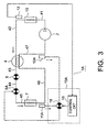
- the refrigeration cycle is designated by a reference numeral 1A and is similar to the above-described refrigeration cycle 1 of Fig. 1 in basic constitution thereof.
- the refrigeration cycle 1A includes a superheat control valve 6A in place of the superheat control valve 6 in Fig. 1.
- the superheat control valve 6A is connected between the evaporator 7 and the internal heat exchanger 4 and is for adjusting the open degree thereof in accordance with pressure which is supplied to the superheat control value 6A.
- the refrigeration cycle 1A is provided with first and second temperature sensitive cylinders 10A and 11A which are known in the art.
- the first and the second temperature sensitive cylinders 10A and 11A are responsive to the temperatures of the gas phase part and the evaporated part of the refrigerant and are for producing pressure values as the first and the second temperature signals, respectively.
- the pressure values are selectively supplied to the superheat control valve 6A in the manner which will later be described.
- a change-over selector 13A is constituted using a change-over valve 16 instead of the change-over switch 14 in Fig. 1.
- the change-over valve 16 supplies either of the pressure values or the detected pressures of the first and the second temperature sensitive cylinders 10A and 11A to the superheat control valve 6A in accordance with the change-over control signal from the control circuit 15.
- the superheat control valve 6A is of a mechanical type to mechanically adjust the open degree of the valve in accordance with either of the detected pressures of the first and the second temperature sensitive cylinders 10A and 11A.
- first step S101 when the refrigeration cycle 1A starts, a timer starts (first step S101).
- the change-over valve 16 supplies the detected pressure from the first temperature sensitive cylinder 10A to the superheat control valve 6A.
- the open degree of the superheat control valve 6A is adjusted based on the detected pressure of the first temperature sensitive cylinder 10, thereby controlling the refrigerant flow rate to the evaporator 7 (second step S102).
- second step S102 it is judged whether or not a predetermined time t 0 elapses from the start of the refrigeration cycle 1A (third step S103).
- the second step S102 is continued.
- the detected pressure Pa is compared with the stored pressure Pi corresponding to the stored temperature Ti having the same value as that of the detected temperature Ta. Namely, judgement is made about whether or not (Pi - Pa) exceeds a first predetermined value P S1 (fourth step S104).
- P S1 a first predetermined value
- the opening/closing control of the superheat control valve 6A based on the detected pressure of the first temperature sensitive cylinder 10A is continued (second step S102).
- the control circuit 15 transmits a change-over control signal to the change-over valve 16.
- the pressure detected by the second temperature sensitive cylinder 11A is supplied to the superheat control valve 6A.
- the open degree of the superheat control valve 6A is adjusted based on the detected pressure of the second temperature sensitive cylinder 11A instead of the detected pressure of the first temperature sensitive cylinder 10A (fifth step S105).
- the opening/closing control of the superheat control valve 6A based on the pressure detected by the second temperature sensitive cylinder 11A is continued (fifth step S105).
- the control circuit 15 transmits a stop signal to the operation control circuit (not shown) and the operation of the refrigeration cycle 1A is stopped. This can avoid disadvantages caused when the refrigerant excessively leaks from the refrigeration cycle 1A, such as the sticking of the compressor 2.
- the change-over selector 13 will be operable as the judging arrangement.
- the change-over selector 13 On carrying out the fifth step S105. the change-over selector 13 will be operable as the first making arrangement.
- the change-over selector 13 On carrying out the second step S102, the change-over selector 13 will be operable as the second making arrangement.
- the effect similar to that of the first embodiment can be obtained. Specifically, the deterioration of the refrigerating ability caused by the refrigerant leakage can be prevented without disposing the gas-liquid separator in the refrigeration cycle. Moreover, since the gas-liquid separator is unnecessary, the manufacture cost can be reduced. Furthermore, the present embodiment can preferably be applied to the refrigeration system for car air conditioning in which the refrigerant leakage is easily generated by vibration.
- the vapor compression type refrigeration cycle in which, by constituting the circuit without using the gas-liquid separator, the cost reduction is realized, and the ability deterioration with the refrigerant leakage can be prevented.
Landscapes
- Engineering & Computer Science (AREA)
- Physics & Mathematics (AREA)
- Mechanical Engineering (AREA)
- Thermal Sciences (AREA)
- General Engineering & Computer Science (AREA)
- Chemical & Material Sciences (AREA)
- Chemical Kinetics & Catalysis (AREA)
- Air-Conditioning For Vehicles (AREA)
Applications Claiming Priority (2)
| Application Number | Priority Date | Filing Date | Title |
|---|---|---|---|
| JP10360638A JP2000179960A (ja) | 1998-12-18 | 1998-12-18 | 蒸気圧縮式冷凍サイクル |
| JP36063898 | 1998-12-18 |
Publications (1)
| Publication Number | Publication Date |
|---|---|
| EP1014013A1 true EP1014013A1 (de) | 2000-06-28 |
Family
ID=18470276
Family Applications (1)
| Application Number | Title | Priority Date | Filing Date |
|---|---|---|---|
| EP99125221A Withdrawn EP1014013A1 (de) | 1998-12-18 | 1999-12-17 | Kältekreislauf mit Dampfverdichtung |
Country Status (2)
| Country | Link |
|---|---|
| EP (1) | EP1014013A1 (de) |
| JP (1) | JP2000179960A (de) |
Cited By (22)
| Publication number | Priority date | Publication date | Assignee | Title |
|---|---|---|---|---|
| WO2002031416A1 (fr) * | 2000-10-12 | 2002-04-18 | Valeo Climatisation | Dispositif de climatisation de vehicule utilisant un cycle supercritique |
| EP1202004A1 (de) * | 2000-10-30 | 2002-05-02 | Calsonic Kansei Corporation | Kühlungskreislauf und Steuerungsverfahren dafür |
| EP1207360A3 (de) * | 2000-11-15 | 2002-08-28 | Carrier Corporation | Wärmetauscher mit Saugleitung und Tank für einen transkritischen Dampfkompressionskreislauf |
| WO2003106900A1 (de) * | 2002-06-01 | 2003-12-24 | Felix Kalberer | Verfahren zum regeln eines carnot-kreisprozesses sowie anlage zu seiner durchführung |
| EP1347251A3 (de) * | 2002-03-20 | 2004-04-28 | Carrier Corporation | Verfahren zum Erhöhen der Leistungsfähigkeit einer Dampfverdichtungsanordnung mittels Verdampferheizung |
| WO2004053406A1 (de) * | 2002-12-11 | 2004-06-24 | Bms-Energietechnik Ag | Verdampfungsprozesssteuerung in der kältetechnik |
| EP1538405A3 (de) * | 2003-12-01 | 2005-07-13 | Matsushita Electric Industrial Co., Ltd. | Kältekreislaufgerät |
| WO2006087004A1 (en) * | 2005-02-18 | 2006-08-24 | Carrier Corporation | Control of a refrigeration circuit with an internal heat exchanger |
| RU2368850C2 (ru) * | 2005-02-18 | 2009-09-27 | Кэрриер Корпорейшн | Устройство управления холодильного контура с внутренним теплообменником |
| EP1632733A3 (de) * | 2004-09-07 | 2010-04-21 | Panasonic Corporation | Vorrichtung mit einem Kühlkreislauf und Verfahren zur Regelung |
| US20110067435A1 (en) * | 2008-05-20 | 2011-03-24 | Akira Kaneko | Refrigeration cycle |
| CN101644502B (zh) * | 2005-02-18 | 2011-04-20 | 卡里尔公司 | 制冷回路及用于运行该制冷回路的方法 |
| US8141381B2 (en) | 2006-03-27 | 2012-03-27 | Mayekawa Mfg. Co., Ltd. | Vapor compression refrigerating cycle, control method thereof, and refrigerating apparatus to which the cycle and the control method are applied |
| EP2068096A4 (de) * | 2006-09-11 | 2013-03-27 | Daikin Ind Ltd | Kühlvorrichtung |
| CN103403475A (zh) * | 2011-08-31 | 2013-11-20 | 三菱重工业株式会社 | 超临界循环以及利用了该超临界循环的热泵供给热水机 |
| WO2020113949A1 (zh) * | 2018-12-06 | 2020-06-11 | 中车大连机车研究所有限公司 | 一种二氧化碳空调及压力控制和保护方法 |
| DE102019001638A1 (de) * | 2019-03-08 | 2020-09-10 | Stiebel Eltron Gmbh & Co. Kg | Verfahren zum Betreiben einer Wärmepumpe mit einem Dampfkompressionssystem |
| CN112325454A (zh) * | 2020-10-12 | 2021-02-05 | 广州鼎汉轨道交通车辆装备有限公司 | 中高速轨道车辆用co2制冷剂空调机组及方法 |
| EP3922931A1 (de) * | 2020-06-09 | 2021-12-15 | Stiebel Eltron GmbH & Co. KG | Verfahren zum betrieb einer kompressionskälteanlage |
| EP3922932A1 (de) * | 2020-06-09 | 2021-12-15 | Stiebel Eltron GmbH & Co. KG | Verfahren zum betreiben einer kompressionskälteanlage und kompressionskälteanlage |
| EP4170263A1 (de) * | 2021-10-20 | 2023-04-26 | Thermo King LLC | Wärmepumpe, verfahren zum betrieb und zur simulation |
| US11732939B2 (en) | 2018-04-13 | 2023-08-22 | Carrier Corporation | Detection apparatus and method for refrigerant leakage of air source heat pump system |
Families Citing this family (3)
| Publication number | Priority date | Publication date | Assignee | Title |
|---|---|---|---|---|
| KR100496376B1 (ko) * | 2003-03-31 | 2005-06-22 | 한명범 | 냉동사이클용 에너지효율 개선장치 |
| CN104279752A (zh) * | 2014-11-03 | 2015-01-14 | 云南师范大学 | 一种回热式高效低温空气源热泵系统 |
| CN107289599B (zh) * | 2017-08-10 | 2020-03-17 | 四川长虹电器股份有限公司 | 一种检测空调冷媒泄露量的装置和方法 |
Citations (8)
| Publication number | Priority date | Publication date | Assignee | Title |
|---|---|---|---|---|
| US2922292A (en) * | 1956-05-03 | 1960-01-26 | Sporlan Valve Co | Valve assembly for a refrigeration system |
| US2943643A (en) * | 1956-12-21 | 1960-07-05 | Gen Electric | Flow modulating device |
| US3478534A (en) * | 1967-08-11 | 1969-11-18 | Controls Co Of America | Thermistor controlled refrigeration expansion valve |
| US4461635A (en) * | 1981-10-01 | 1984-07-24 | Danfoss A/S | Cryopump or heat pump circuit |
| FR2539855A1 (fr) * | 1983-01-25 | 1984-07-27 | Comp Generale Electricite | Procede et dispositif de reglage du taux de detente dans une vanne de detente du fluide frigorifique d'un cycle de pompe a chaleur |
| DE3442169A1 (de) * | 1984-11-17 | 1986-05-28 | Süddeutsche Kühlerfabrik Julius Fr. Behr GmbH & Co KG, 7000 Stuttgart | Verfahren zum regeln eines kaeltekreisprozesses fuer eine waermepumpe oder eine kaeltemaschine und eine waermepumpe oder kaeltemaschine hierzu |
| DE19631914A1 (de) * | 1995-08-09 | 1997-02-13 | Aisin Seiki | Überkritisch betriebene Verdichter-Kältemaschine |
| JPH10141822A (ja) * | 1996-11-07 | 1998-05-29 | Hoshizaki Electric Co Ltd | ドラム型製氷機 |
-
1998
- 1998-12-18 JP JP10360638A patent/JP2000179960A/ja active Pending
-
1999
- 1999-12-17 EP EP99125221A patent/EP1014013A1/de not_active Withdrawn
Patent Citations (8)
| Publication number | Priority date | Publication date | Assignee | Title |
|---|---|---|---|---|
| US2922292A (en) * | 1956-05-03 | 1960-01-26 | Sporlan Valve Co | Valve assembly for a refrigeration system |
| US2943643A (en) * | 1956-12-21 | 1960-07-05 | Gen Electric | Flow modulating device |
| US3478534A (en) * | 1967-08-11 | 1969-11-18 | Controls Co Of America | Thermistor controlled refrigeration expansion valve |
| US4461635A (en) * | 1981-10-01 | 1984-07-24 | Danfoss A/S | Cryopump or heat pump circuit |
| FR2539855A1 (fr) * | 1983-01-25 | 1984-07-27 | Comp Generale Electricite | Procede et dispositif de reglage du taux de detente dans une vanne de detente du fluide frigorifique d'un cycle de pompe a chaleur |
| DE3442169A1 (de) * | 1984-11-17 | 1986-05-28 | Süddeutsche Kühlerfabrik Julius Fr. Behr GmbH & Co KG, 7000 Stuttgart | Verfahren zum regeln eines kaeltekreisprozesses fuer eine waermepumpe oder eine kaeltemaschine und eine waermepumpe oder kaeltemaschine hierzu |
| DE19631914A1 (de) * | 1995-08-09 | 1997-02-13 | Aisin Seiki | Überkritisch betriebene Verdichter-Kältemaschine |
| JPH10141822A (ja) * | 1996-11-07 | 1998-05-29 | Hoshizaki Electric Co Ltd | ドラム型製氷機 |
Non-Patent Citations (1)
| Title |
|---|
| PATENT ABSTRACTS OF JAPAN vol. 1998, no. 10 31 August 1998 (1998-08-31) * |
Cited By (33)
| Publication number | Priority date | Publication date | Assignee | Title |
|---|---|---|---|---|
| US6786057B2 (en) | 2000-10-12 | 2004-09-07 | Valeo Climatisation | Vehicle air conditioning device using a supercritical cycle |
| FR2815397A1 (fr) * | 2000-10-12 | 2002-04-19 | Valeo Climatisation | Dispositif de climatisation de vehicule utilisant un cycle supercritique |
| WO2002031416A1 (fr) * | 2000-10-12 | 2002-04-18 | Valeo Climatisation | Dispositif de climatisation de vehicule utilisant un cycle supercritique |
| EP1202004A1 (de) * | 2000-10-30 | 2002-05-02 | Calsonic Kansei Corporation | Kühlungskreislauf und Steuerungsverfahren dafür |
| US6523360B2 (en) | 2000-10-30 | 2003-02-25 | Calsonic Kansei Corporation | Cooling cycle and control method thereof |
| EP1207360A3 (de) * | 2000-11-15 | 2002-08-28 | Carrier Corporation | Wärmetauscher mit Saugleitung und Tank für einen transkritischen Dampfkompressionskreislauf |
| EP1347251A3 (de) * | 2002-03-20 | 2004-04-28 | Carrier Corporation | Verfahren zum Erhöhen der Leistungsfähigkeit einer Dampfverdichtungsanordnung mittels Verdampferheizung |
| WO2003106900A1 (de) * | 2002-06-01 | 2003-12-24 | Felix Kalberer | Verfahren zum regeln eines carnot-kreisprozesses sowie anlage zu seiner durchführung |
| CH695464A5 (de) * | 2002-06-12 | 2006-05-31 | Felix Kalberer | Wärmepumpe. |
| WO2004053406A1 (de) * | 2002-12-11 | 2004-06-24 | Bms-Energietechnik Ag | Verdampfungsprozesssteuerung in der kältetechnik |
| US7665321B2 (en) | 2002-12-11 | 2010-02-23 | Bms-Energietechnik Ag | Evaporation process control used in refrigeration |
| EP1538405A3 (de) * | 2003-12-01 | 2005-07-13 | Matsushita Electric Industrial Co., Ltd. | Kältekreislaufgerät |
| EP1632733A3 (de) * | 2004-09-07 | 2010-04-21 | Panasonic Corporation | Vorrichtung mit einem Kühlkreislauf und Verfahren zur Regelung |
| AU2005327828B2 (en) * | 2005-02-18 | 2010-09-30 | Carrier Corporation | Control of a refrigeration circuit with an internal heat exchanger |
| CN100587368C (zh) * | 2005-02-18 | 2010-02-03 | 卡里尔公司 | 具有内部热交换器的制冷回路的控制 |
| RU2368850C2 (ru) * | 2005-02-18 | 2009-09-27 | Кэрриер Корпорейшн | Устройство управления холодильного контура с внутренним теплообменником |
| WO2006087004A1 (en) * | 2005-02-18 | 2006-08-24 | Carrier Corporation | Control of a refrigeration circuit with an internal heat exchanger |
| CN101644502B (zh) * | 2005-02-18 | 2011-04-20 | 卡里尔公司 | 制冷回路及用于运行该制冷回路的方法 |
| US8069684B2 (en) | 2005-02-18 | 2011-12-06 | Carrier Corporation | Control of a refrigeration circuit with an internal heat exchanger |
| US8141381B2 (en) | 2006-03-27 | 2012-03-27 | Mayekawa Mfg. Co., Ltd. | Vapor compression refrigerating cycle, control method thereof, and refrigerating apparatus to which the cycle and the control method are applied |
| EP2068096A4 (de) * | 2006-09-11 | 2013-03-27 | Daikin Ind Ltd | Kühlvorrichtung |
| US20110067435A1 (en) * | 2008-05-20 | 2011-03-24 | Akira Kaneko | Refrigeration cycle |
| CN103403475A (zh) * | 2011-08-31 | 2013-11-20 | 三菱重工业株式会社 | 超临界循环以及利用了该超临界循环的热泵供给热水机 |
| US11732939B2 (en) | 2018-04-13 | 2023-08-22 | Carrier Corporation | Detection apparatus and method for refrigerant leakage of air source heat pump system |
| WO2020113949A1 (zh) * | 2018-12-06 | 2020-06-11 | 中车大连机车研究所有限公司 | 一种二氧化碳空调及压力控制和保护方法 |
| DE102019001638A1 (de) * | 2019-03-08 | 2020-09-10 | Stiebel Eltron Gmbh & Co. Kg | Verfahren zum Betreiben einer Wärmepumpe mit einem Dampfkompressionssystem |
| EP3730873A3 (de) * | 2019-03-08 | 2021-06-23 | Stiebel Eltron GmbH & Co. KG | Verfahren zum betrieben einer wäremepumpe mit einem dampfkompressionssystem |
| EP3922931A1 (de) * | 2020-06-09 | 2021-12-15 | Stiebel Eltron GmbH & Co. KG | Verfahren zum betrieb einer kompressionskälteanlage |
| EP3922932A1 (de) * | 2020-06-09 | 2021-12-15 | Stiebel Eltron GmbH & Co. KG | Verfahren zum betreiben einer kompressionskälteanlage und kompressionskälteanlage |
| CN112325454A (zh) * | 2020-10-12 | 2021-02-05 | 广州鼎汉轨道交通车辆装备有限公司 | 中高速轨道车辆用co2制冷剂空调机组及方法 |
| EP4170263A1 (de) * | 2021-10-20 | 2023-04-26 | Thermo King LLC | Wärmepumpe, verfahren zum betrieb und zur simulation |
| EP4170262A1 (de) * | 2021-10-20 | 2023-04-26 | Thermo King Corporation | Wärmepumpe, verfahren zum betrieb und zur simulation |
| US12123634B2 (en) | 2021-10-20 | 2024-10-22 | Thermo King Llc | Heat pump, methods of operation and simulation |
Also Published As
| Publication number | Publication date |
|---|---|
| JP2000179960A (ja) | 2000-06-30 |
Similar Documents
| Publication | Publication Date | Title |
|---|---|---|
| EP1014013A1 (de) | Kältekreislauf mit Dampfverdichtung | |
| EP2224191B1 (de) | Klimaanlage und Steuerverfahren dafür | |
| JP5027160B2 (ja) | フラッシュタンク受器を有する冷媒蒸気圧縮システム | |
| US7559206B2 (en) | Supercritical heat pump cycle system | |
| CN107076475B (zh) | 用于运行具有接收器的蒸气压缩系统的方法 | |
| US20080022706A1 (en) | Two-stage expansion refrigerating device | |
| JP4408413B2 (ja) | 冷凍装置及びこれを用いた空気調和機 | |
| EP3798533B1 (de) | Verfahren zur steuerung des saugdrucks eines dampfkompressionssystems | |
| JP2010526985A (ja) | フラッシュタンクエコノマイザを備えた冷媒蒸気圧縮システム | |
| JP2010525292A (ja) | 遷臨界動作における冷媒蒸気圧縮システムおよびその方法 | |
| JP4202505B2 (ja) | 蒸気圧縮式冷凍サイクル | |
| CN114096424A (zh) | 用于运行车辆的制冷设备的制冷剂回路的方法 | |
| JPH10288411A (ja) | 蒸気圧縮式冷凍サイクル | |
| CN114151935A (zh) | 一种空调系统 | |
| US20060150650A1 (en) | Expansion valve for refrigerating cycle | |
| JP2003130481A (ja) | 自動車用空調装置の蒸気圧縮式冷凍サイクル | |
| JP2003269809A (ja) | 冷却装置及び恒温装置 | |
| JP2002228282A (ja) | 冷凍装置 | |
| WO2004068045A1 (en) | Supercritical refrigerating cycle | |
| JP3479747B2 (ja) | 冷房サイクル制御装置 | |
| WO2000068621A1 (en) | Method of controlling refrigerating cycle and refrigerating cycle using the method | |
| JP2757685B2 (ja) | 空気調和装置の運転制御装置 | |
| JP2003121012A (ja) | 自動車用空調装置の蒸気圧縮式冷凍サイクルの制御方法及び蒸気圧縮式冷凍回路 | |
| EP4474733A1 (de) | Verfahren zum betrieb eines expansionsventils in einem kältemittelkreislauf und kältemittelkreislauf für ein heizungs-, lüftungs-, klima- und kältesystem | |
| JP2004162998A (ja) | 車両用冷凍装置、およびその制御方法 |
Legal Events
| Date | Code | Title | Description |
|---|---|---|---|
| PUAI | Public reference made under article 153(3) epc to a published international application that has entered the european phase |
Free format text: ORIGINAL CODE: 0009012 |
|
| AK | Designated contracting states |
Kind code of ref document: A1 Designated state(s): AT BE CH CY DE DK ES FI FR GB GR IE IT LI LU MC NL PT SE |
|
| AX | Request for extension of the european patent |
Free format text: AL;LT;LV;MK;RO;SI |
|
| AKX | Designation fees paid | ||
| STAA | Information on the status of an ep patent application or granted ep patent |
Free format text: STATUS: THE APPLICATION IS DEEMED TO BE WITHDRAWN |
|
| 18D | Application deemed to be withdrawn |
Effective date: 20001229 |