EP1014075B1 - Procédé et dispositif pour la détection de particules dans des gaz réactifs et toxiques - Google Patents
Procédé et dispositif pour la détection de particules dans des gaz réactifs et toxiques Download PDFInfo
- Publication number
- EP1014075B1 EP1014075B1 EP99124854A EP99124854A EP1014075B1 EP 1014075 B1 EP1014075 B1 EP 1014075B1 EP 99124854 A EP99124854 A EP 99124854A EP 99124854 A EP99124854 A EP 99124854A EP 1014075 B1 EP1014075 B1 EP 1014075B1
- Authority
- EP
- European Patent Office
- Prior art keywords
- gas
- particles
- pressurized gas
- particle
- pressure
- Prior art date
- Legal status (The legal status is an assumption and is not a legal conclusion. Google has not performed a legal analysis and makes no representation as to the accuracy of the status listed.)
- Expired - Lifetime
Links
- 239000002245 particle Substances 0.000 title claims abstract description 115
- 238000000034 method Methods 0.000 title claims abstract description 47
- 239000002341 toxic gas Substances 0.000 title abstract description 8
- 230000005494 condensation Effects 0.000 claims abstract description 41
- 238000009833 condensation Methods 0.000 claims abstract description 41
- 239000012530 fluid Substances 0.000 claims abstract description 35
- 238000009826 distribution Methods 0.000 claims abstract description 27
- 239000000463 material Substances 0.000 claims abstract description 10
- 238000005260 corrosion Methods 0.000 claims abstract description 9
- 230000007797 corrosion Effects 0.000 claims abstract description 9
- 238000006243 chemical reaction Methods 0.000 claims abstract description 7
- 238000004891 communication Methods 0.000 claims abstract description 5
- 230000003287 optical effect Effects 0.000 claims description 15
- 238000001514 detection method Methods 0.000 claims description 12
- QGZKDVFQNNGYKY-UHFFFAOYSA-N Ammonia Chemical compound N QGZKDVFQNNGYKY-UHFFFAOYSA-N 0.000 claims description 7
- 229910015844 BCl3 Inorganic materials 0.000 claims description 7
- KZBUYRJDOAKODT-UHFFFAOYSA-N Chlorine Chemical compound ClCl KZBUYRJDOAKODT-UHFFFAOYSA-N 0.000 claims description 7
- 239000000203 mixture Substances 0.000 claims description 7
- FAQYAMRNWDIXMY-UHFFFAOYSA-N trichloroborane Chemical compound ClB(Cl)Cl FAQYAMRNWDIXMY-UHFFFAOYSA-N 0.000 claims description 7
- 229910015148 B2H6 Inorganic materials 0.000 claims description 6
- 229910015900 BF3 Inorganic materials 0.000 claims description 6
- XPDWGBQVDMORPB-UHFFFAOYSA-N Fluoroform Chemical compound FC(F)F XPDWGBQVDMORPB-UHFFFAOYSA-N 0.000 claims description 6
- 229910007264 Si2H6 Inorganic materials 0.000 claims description 6
- 229910003910 SiCl4 Inorganic materials 0.000 claims description 6
- 229910004014 SiF4 Inorganic materials 0.000 claims description 6
- BLRPTPMANUNPDV-UHFFFAOYSA-N Silane Chemical compound [SiH4] BLRPTPMANUNPDV-UHFFFAOYSA-N 0.000 claims description 6
- RBFQJDQYXXHULB-UHFFFAOYSA-N arsane Chemical compound [AsH3] RBFQJDQYXXHULB-UHFFFAOYSA-N 0.000 claims description 6
- 229910000070 arsenic hydride Inorganic materials 0.000 claims description 6
- WTEOIRVLGSZEPR-UHFFFAOYSA-N boron trifluoride Chemical compound FB(F)F WTEOIRVLGSZEPR-UHFFFAOYSA-N 0.000 claims description 6
- PZPGRFITIJYNEJ-UHFFFAOYSA-N disilane Chemical compound [SiH3][SiH3] PZPGRFITIJYNEJ-UHFFFAOYSA-N 0.000 claims description 6
- 229910000069 nitrogen hydride Inorganic materials 0.000 claims description 6
- 229910000073 phosphorus hydride Inorganic materials 0.000 claims description 6
- FDNAPBUWERUEDA-UHFFFAOYSA-N silicon tetrachloride Chemical compound Cl[Si](Cl)(Cl)Cl FDNAPBUWERUEDA-UHFFFAOYSA-N 0.000 claims description 6
- ABTOQLMXBSRXSM-UHFFFAOYSA-N silicon tetrafluoride Chemical compound F[Si](F)(F)F ABTOQLMXBSRXSM-UHFFFAOYSA-N 0.000 claims description 6
- 229910052751 metal Inorganic materials 0.000 claims description 5
- 239000002184 metal Substances 0.000 claims description 5
- SIJZIPMRLFRVHV-UHFFFAOYSA-N 1,1,2,2,3,3,4,4,5-nonafluoro-5,6,6-tris(trifluoromethyl)cyclohexane Chemical compound FC(F)(F)C1(F)C(F)(F)C(F)(F)C(F)(F)C(F)(F)C1(C(F)(F)F)C(F)(F)F SIJZIPMRLFRVHV-UHFFFAOYSA-N 0.000 claims description 3
- 239000007789 gas Substances 0.000 abstract description 139
- 239000011261 inert gas Substances 0.000 abstract description 8
- 238000012545 processing Methods 0.000 abstract description 8
- 230000008569 process Effects 0.000 description 14
- 239000000443 aerosol Substances 0.000 description 12
- 239000000356 contaminant Substances 0.000 description 12
- 230000009467 reduction Effects 0.000 description 9
- 231100000331 toxic Toxicity 0.000 description 9
- 230000002588 toxic effect Effects 0.000 description 9
- 238000005259 measurement Methods 0.000 description 7
- FAPWRFPIFSIZLT-UHFFFAOYSA-M Sodium chloride Chemical compound [Na+].[Cl-] FAPWRFPIFSIZLT-UHFFFAOYSA-M 0.000 description 6
- 238000011109 contamination Methods 0.000 description 6
- 239000000126 substance Substances 0.000 description 6
- VEXZGXHMUGYJMC-UHFFFAOYSA-N Hydrochloric acid Chemical compound Cl VEXZGXHMUGYJMC-UHFFFAOYSA-N 0.000 description 5
- CPELXLSAUQHCOX-UHFFFAOYSA-N Hydrogen bromide Chemical compound Br CPELXLSAUQHCOX-UHFFFAOYSA-N 0.000 description 5
- 238000000149 argon plasma sintering Methods 0.000 description 5
- IJGRMHOSHXDMSA-UHFFFAOYSA-N Atomic nitrogen Chemical compound N#N IJGRMHOSHXDMSA-UHFFFAOYSA-N 0.000 description 4
- 239000004809 Teflon Substances 0.000 description 4
- 229920006362 Teflon® Polymers 0.000 description 4
- 230000007547 defect Effects 0.000 description 4
- 230000006911 nucleation Effects 0.000 description 4
- 238000010899 nucleation Methods 0.000 description 4
- 230000001590 oxidative effect Effects 0.000 description 4
- 238000001816 cooling Methods 0.000 description 3
- 238000009792 diffusion process Methods 0.000 description 3
- 238000009413 insulation Methods 0.000 description 3
- 238000004377 microelectronic Methods 0.000 description 3
- 238000005070 sampling Methods 0.000 description 3
- 229920006395 saturated elastomer Polymers 0.000 description 3
- 239000011780 sodium chloride Substances 0.000 description 3
- 238000011144 upstream manufacturing Methods 0.000 description 3
- LRHPLDYGYMQRHN-UHFFFAOYSA-N N-Butanol Chemical compound CCCCO LRHPLDYGYMQRHN-UHFFFAOYSA-N 0.000 description 2
- 230000002411 adverse Effects 0.000 description 2
- 229910045601 alloy Inorganic materials 0.000 description 2
- 239000000956 alloy Substances 0.000 description 2
- 230000003749 cleanliness Effects 0.000 description 2
- 238000013461 design Methods 0.000 description 2
- 238000010790 dilution Methods 0.000 description 2
- 239000012895 dilution Substances 0.000 description 2
- 230000005684 electric field Effects 0.000 description 2
- 231100001261 hazardous Toxicity 0.000 description 2
- 150000002430 hydrocarbons Chemical class 0.000 description 2
- 239000007788 liquid Substances 0.000 description 2
- 238000004519 manufacturing process Methods 0.000 description 2
- 229910052757 nitrogen Inorganic materials 0.000 description 2
- 239000004033 plastic Substances 0.000 description 2
- 239000010453 quartz Substances 0.000 description 2
- VYPSYNLAJGMNEJ-UHFFFAOYSA-N silicon dioxide Inorganic materials O=[Si]=O VYPSYNLAJGMNEJ-UHFFFAOYSA-N 0.000 description 2
- 238000003860 storage Methods 0.000 description 2
- 238000013022 venting Methods 0.000 description 2
- NZXAVWBNLOQPGY-UHFFFAOYSA-N 1,1,2,2,3,3,4,4,5,5,6,6,7,7,8,8-hexadecafluoro-4a,8a-bis(trifluoromethyl)naphthalene Chemical compound FC(F)(F)C12C(F)(F)C(F)(F)C(F)(F)C(F)(F)C1(C(F)(F)F)C(F)(F)C(F)(F)C(F)(F)C2(F)F NZXAVWBNLOQPGY-UHFFFAOYSA-N 0.000 description 1
- 229920004943 Delrin® Polymers 0.000 description 1
- LFQSCWFLJHTTHZ-UHFFFAOYSA-N Ethanol Chemical compound CCO LFQSCWFLJHTTHZ-UHFFFAOYSA-N 0.000 description 1
- 229910000792 Monel Inorganic materials 0.000 description 1
- 230000008901 benefit Effects 0.000 description 1
- 238000009835 boiling Methods 0.000 description 1
- 239000002131 composite material Substances 0.000 description 1
- 238000012937 correction Methods 0.000 description 1
- 238000007865 diluting Methods 0.000 description 1
- 230000000694 effects Effects 0.000 description 1
- 230000002708 enhancing effect Effects 0.000 description 1
- 238000011156 evaluation Methods 0.000 description 1
- 238000002474 experimental method Methods 0.000 description 1
- 239000010419 fine particle Substances 0.000 description 1
- 229930195733 hydrocarbon Natural products 0.000 description 1
- 239000001257 hydrogen Substances 0.000 description 1
- 229910052739 hydrogen Inorganic materials 0.000 description 1
- 125000004435 hydrogen atom Chemical class [H]* 0.000 description 1
- -1 i.e. Substances 0.000 description 1
- 230000006872 improvement Effects 0.000 description 1
- 239000012535 impurity Substances 0.000 description 1
- 229910001026 inconel Inorganic materials 0.000 description 1
- 239000003701 inert diluent Substances 0.000 description 1
- DNNSSWSSYDEUBZ-OUBTZVSYSA-N krypton-85 Chemical compound [85Kr] DNNSSWSSYDEUBZ-OUBTZVSYSA-N 0.000 description 1
- 230000031700 light absorption Effects 0.000 description 1
- 238000000691 measurement method Methods 0.000 description 1
- 238000012986 modification Methods 0.000 description 1
- 230000004048 modification Effects 0.000 description 1
- 238000012544 monitoring process Methods 0.000 description 1
- 150000002894 organic compounds Chemical class 0.000 description 1
- 230000005855 radiation Effects 0.000 description 1
- 230000004044 response Effects 0.000 description 1
- 238000009738 saturating Methods 0.000 description 1
- 239000004065 semiconductor Substances 0.000 description 1
- 230000035945 sensitivity Effects 0.000 description 1
- 238000010998 test method Methods 0.000 description 1
- 239000012780 transparent material Substances 0.000 description 1
- 239000011882 ultra-fine particle Substances 0.000 description 1
- 230000008016 vaporization Effects 0.000 description 1
- 238000012795 verification Methods 0.000 description 1
- XLYOFNOQVPJJNP-UHFFFAOYSA-N water Substances O XLYOFNOQVPJJNP-UHFFFAOYSA-N 0.000 description 1
Images

Classifications
-
- G—PHYSICS
- G01—MEASURING; TESTING
- G01N—INVESTIGATING OR ANALYSING MATERIALS BY DETERMINING THEIR CHEMICAL OR PHYSICAL PROPERTIES
- G01N33/00—Investigating or analysing materials by specific methods not covered by groups G01N1/00 - G01N31/00
-
- G—PHYSICS
- G01—MEASURING; TESTING
- G01N—INVESTIGATING OR ANALYSING MATERIALS BY DETERMINING THEIR CHEMICAL OR PHYSICAL PROPERTIES
- G01N15/00—Investigating characteristics of particles; Investigating permeability, pore-volume or surface-area of porous materials
- G01N15/06—Investigating concentration of particle suspensions
- G01N15/065—Investigating concentration of particle suspensions using condensation nuclei counters
-
- Y—GENERAL TAGGING OF NEW TECHNOLOGICAL DEVELOPMENTS; GENERAL TAGGING OF CROSS-SECTIONAL TECHNOLOGIES SPANNING OVER SEVERAL SECTIONS OF THE IPC; TECHNICAL SUBJECTS COVERED BY FORMER USPC CROSS-REFERENCE ART COLLECTIONS [XRACs] AND DIGESTS
- Y10—TECHNICAL SUBJECTS COVERED BY FORMER USPC
- Y10S—TECHNICAL SUBJECTS COVERED BY FORMER USPC CROSS-REFERENCE ART COLLECTIONS [XRACs] AND DIGESTS
- Y10S977/00—Nanotechnology
- Y10S977/902—Specified use of nanostructure
- Y10S977/932—Specified use of nanostructure for electronic or optoelectronic application
- Y10S977/953—Detector using nanostructure
Definitions
- the present invention relates to the field of particle counting in gases, particularly reactive, corrosive gases for the electronics fabrication industry.
- Micro-electronic circuits require many processing steps. Processing is performed using extremely clean gases. However, the amount of contamination needed to produce fatal defects in micro-circuits is extremely small. For example, an individual particle as small as 0.02 micrometer in diameter can result in a fatal defect in a modern microcircuit. Micro-contamination may occur at any time during the many steps needed to complete a circuit. Therefore, tight control of cleanliness in the processing gas is required.
- Modern filters are able to remove particulate contaminants in process gases with an extremely high efficiency.
- the complete assurance of contamination control also requires verification of gas cleanliness.
- An accurate technique for detecting microscopic particles in filtered gases must be available. This technique must be capable of detecting microscopic contaminant particles as small as 0.02 micrometer in reactive or toxic gases used in microchip processing, including but not limited to the following gases: SiCl 4 , PH 3 , B 2 H 6 , AsH 3 , SiF 4 , Si 2 H 6 , NH 3 , BCl 3 , BF 3 , Cl 2 , H 2 , HBr, HCl, HF, NF 3 , N 2 O, O 2 , SiH 4 and WF 6 , as well as inert gases, including, but not limited to such gases as N 2 , Ar, He, CF 4 , CHF 3 , C 2 F 6 and SF 6 .
- the technique should perform the particle measurement at a pressure equal to the process gas system line pressure (about 60 psig).
- the sample gas would not need to be reduced in pressure before entering the measuring instrument. That is, the instrument could be connected directly to the gas line without intermediate pressure reducing devices.
- Measurement at gas line pressure would provide an advantage in particle measurement, since the process of pressure reduction in some gases can produce adverse effects such as particle shear-off or nucleation of impurities in the pressure reduction device. Such objects produced by shear-off or nucleation would be falsely interpreted by the downstream particle counting instrument as gas line contaminant particles.
- venting a portion of hazardous and expensive gases before the remaining sample can enter the instrument.
- Such venting is costly, environmentally damaging, and may require increased flow capacities through vent system emission control devices.
- condensation of the process gas into liquid droplets may occur during the process of pressure reduction, especially when sampling high boiling point and easily condensed gases such as HF, WF 6 and BCl 3 .
- condensation droplets also would be falsely interpreted by the downstream particle counting instrument as gas line contaminant particles.
- CNCs condensation nucleus counters
- These instruments use continuous conductive cooling, continuous cooling through dilution, or cooling through expansion to create a supersaturated aerosol mixture.
- Various substances have been used as a saturating medium, including water, alcohol (e.g ., butanol) and perfluorinated organic compounds, such as perfluorodimethyldecalin.
- the fine particles act as nucleation sites for vapor condensation and subsequent droplet growth. Droplets grow to sufficient size to permit detection by conventional light scattering or light absorption techniques with negligible accompanying noise.
- U. S. Pat. No. 4,293,217 discloses a continuous flow CNC and process for detecting small contaminants in gas streams. Additional patents pertaining to CNC's include U. S. Pat. Nos. 3,806,248 and 3,632,210 .
- the measurement techniques in the above references are capable in some cases of detecting particles in H 2 and O 2 , and can in some cases detect particles as small as 0.003 micrometer. However, those techniques do not detect particles at gas pressures above 0 psig in toxic or other reactive gases, such as SiCl 4 , PH 3 , B 2 H 6 , AsH 3 , SiF 4 , Si 2 H 6 , NH 3 , BCl 3 , BF 3 , Cl 2 , HBr, HCl, HF, NF 3 , N 2 O, SiH 4 and WF 6 .
- toxic or other reactive gases such as SiCl 4 , PH 3 , B 2 H 6 , AsH 3 , SiF 4 , Si 2 H 6 , NH 3 , BCl 3 , BF 3 , Cl 2 , HBr, HCl, HF, NF 3 , N 2 O, SiH 4 and WF 6 .
- the prior CNCs were not constructed to contain gas pressures greater than 0 psig, or to prevent possible leakage of reactive or toxic gases under pressure. Therefore, the prior CNCs require upstream pressure reduction when sampling from pressurized gas sources.
- US patent 5,231,865 discloses a diffusion diluter and a method for using such apparatus with a condension nucleus counter, wherein a particle containing reactive gas is diluted with an inert diluted gas to diminish the reactive character of particle-containing gas without disturbing the particle concentration of the gas allowing it to be measured for its particle content. Since condensation nucleus counters are designed to receive gas samples at standard temperature and pressure, the diffusion diluter can be operated at about 1 atmosphere and 21 °C.
- the present invention is an apparatus according to claim 1 and a method for detecting particles in a particle-contalning gas according to claim 6.
- the invention can detect sub-0.1 micrometer contaminant particles in pressurized reactive or toxic gases, including but not limited to SiCl 4 , PH 3 , B 2 H 6 , AsH 3, SiF 4 , Si 2 H 6 , NH 3 , BCl 3 , BF 3 , Cl 2 , H 2 , HBr, HCl, HF, NF 3 , N 2 O, O 2 , SiH 4 , WF 6 , and mixtures thereof, as well as inert gases, including but not limited to N 2 , Ar, He, CF 4 , CHF 3 , C 2 F 6 , and SF 6 , and mixtures thereof.
- pressurized reactive or toxic gases including but not limited to SiCl 4 , PH 3 , B 2 H 6 , AsH 3, SiF 4 , Si 2 H 6 , NH 3 , BCl
- the apparatus includes a gas distribution line containing a pressurized gas having a pressure up to about 414 000 Pa over atmospheric pressure (60 psig) and a condensation nucleus counter in fluid communication with the pressurized gas in the gas distribution line.
- the condensation nucleus counter is adapted to receive a stream of the pressurized gas at a pressure substantially equal to the pressure of the pressurized gas in the gas distribution line.
- the apparatus also includes means for determining the number of particles in the pressurized gas. In yet another embodiment, the apparatus includes means for tabulating the number of the at least one particle.
- the means for tabulating may be a computer.
- the condensation nucleus counter includes the following: (a) a reservoir block; (b) an inlet tube adapted to receive the stream of the pressurized gas and to deliver said stream into the reservoir block; (c) a saturator disposed inside the reservoir block, wherein the saturator is heated by a heater mounted in thermal contact with the reservoir block; (d) a working fluid disposed inside the saturator; (e) a sintered metal wick partially submerged in the working fluid; (f) a condenser adapted to receive a stream of the pressurized gas from the saturator; (g) an aerodynamic focusing nozzle adapted to receive the stream of the pressurized gas stream containing droplets; (h) an optical detection chamber having a droplet sensing device to count and identify the droplets in the pressurized gas stream containing droplets; (i) and an outlet tube adapted to vent the pressurized gas stream containing droplets from the optical detection chamber.
- the condensation nucleus counter is constructed of materials resistant to corrosion and to reaction with any of several pressurized gases, including but not limited to: SiCl 4 , PH 3 , B 2 H 6 , AsH 3, SiF 4 , Si 2 H 6 , NH 3 , BCl 3 , BF 3 , Cl 2 , H 2 , HBr, HCl, HF, NF 3 , N 2 O, O 2 , SiH 4 , WF 6 , N 2 , Ar, He, CF 4 , CHF 3 , C 2 F 6 , and SF 6 , and mixtures thereof.
- pressurized gases including but not limited to: SiCl 4 , PH 3 , B 2 H 6 , AsH 3, SiF 4 , Si 2 H 6 , NH 3 , BCl 3 , BF 3 , Cl 2 , H 2 , HBr, HCl, HF, NF 3 , N 2 O, O 2 , SiH 4 , WF 6 ,
- Another aspect of the invention is a method of detecting particles in a particle-containing gas at a pressure up to about 414 000 Pa over atmospheric pressure (60 psig).
- the method includes multiple steps as follows: (a) providing a gas distribution line containing a pressurized gas at a pressure greater up to about 414 000 Pa over atmospheric pressure (60 psig) (b) providing a condensation nucleus counter in fluid communication with the pressurized gas in the distribution line, wherein the condensation nucleus counter is adapted to receive a stream of pressurized gas at pressures substantially equal to the pressure of the gas in the pressurized gas distribution line; and (c) introducing a stream of the pressurized gas into the condensation nucleus counter at a pressure substantially equal to the pressure of the pressurized gas in the gas distribution line.
- the method includes the additional step of determining the number of particles in the pressurized gas introduced into the condensation nucleus counter.
- the method includes the additional step of tabulating the number of the particles.
- the tabulating step may be performed by a computer.
- the step of determining the number of particles in the pressurized gas comprises the following sub-steps: (a) passing a particle-containing gas mixed with a fluid vapor into a condensation zone; (b) condensing the working fluid vapor on at least one particle in the particle-containing gas having a minimum size corresponding to a minimum temperature of a condensing zone to form at least one droplet; and (c) detecting the droplets and counting the number of droplets by appropriate sensing and tabulation.
- the working fluid may be perfluorotrimethylcyclohexane.
- other fluids may be used, including but not limited to non-reactive fluids, such as Multiflor ® perfluorinated hydrocarbons, available from Air Products and Chemicals, Inc. of Allentown, PA. (Multifluor ® is a registered trademark of Air Products and Chemicals, Inc.)
- the particles in a particle-containing pressurized gas can be detected at an at least approximately 50% counting efficiency.
- a pressure of the gas in such a method is about 414 000 Pa (60 psig).
- the methods may be used for any of several pressurized gases, including but not limited to: SiCl 4 , PH 3 , B 2 H 6 , AsH 3, SiF 4 , Si 2 H 6 , NH 3 , BCl 3 , BF 3 , Cl 2 , H 2 , HBr, HCl, HF, NF 3 , N 2 O, O 2 , SiH 4 , WF 6 , N 2 , Ar, He, CF 4 , CHF 3 , C 2 F 6 , and SF 6 , and mixtures thereof.
- the present invention is an apparatus according to claim 1 and method to detect and measure particles substantially smaller than 0.1 micrometer according to claim 6 in toxic or reactive gases at elevated pressures up to about 414 000 Pa over atmospheric pressure (60 psig).
- the invention is an apparatus method for detecting sub-0.1 micrometer particles in toxic or reactive gases at gas line pressures of about 414 000 Pa (60 psig) using a condensation nucleus counter constructed of materials resistant to corrosion and to reaction with the pressurized toxic or reactive gases.
- the present invention is useful in particle detection in gas distribution systems, including but not limited to systems for delivering gases from a point of storage to a point of utilization. Such systems typically have storage containers, control valves, manifolds, flow controllers, distribution lines and monitoring equipment.
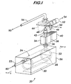
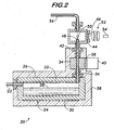
- the present invention includes a gas distribution line (not shown) containing a pressurized gas having a pressure up to about 414 000 Pa over atmospheric pressure (60 psig) and a condensation nucleus counter 20 in fluid communication with the pressurized gas in the gas distribution line.
- the condensation nucleus counter receives a stream 80 of the pressurized gas from the gas distribution line. The stream is at a pressure substantially equal to the pressure of the pressurized gas in the gas distribution line.
- the condensation nucleus counter (CNC) is designed to measure particles substantially smaller than 0.1 micrometer in toxic or reactive gases at elevated pressures.
- the main components of the CNC 20 in the preferred embodiment are:
- the gas inlet tube 22, saturator 24, sintered metal wick 32, condenser 34, aerodynamic focusing nozzle 48, optical detector chamber 44, and gas outlet tube 56 are constructed from Monel alloy, Inconel alloy, or other suitable thermally conducting and corrosion resistant materials, and are properly sized to withstand elevated pressures such as, for example, about 414 000 Pa (60 psig).
- the optical detector chamber windows 46 are constructed from quartz or other suitable corrosion resistant and optically transparent material, and are sized to withstand elevated pressures such as, for example, about 414 000 Pa (60 psig).
- the connectors (36, 42) between the saturator 24 and the condenser 34, and between the condenser and the optical detector chamber 44 are constructed from Teflon plastic, Delrin plastic, or other suitable thermally insulating and corrosion resistant material.
- the thermal insulation provided by these connectors permits the saturator, condenser and optical detector chamber to be thermally isolated from each other and maintained at different operating temperatures.
- the working fluid 28 can consist of any one of the family of non-reactive inert liquids, including but not limited to perfluorotrimethylcyclohexane and other perfluorinated hydrocarbon compounds.
- Such fluids include Multifluor ® fluids, available from Air Products and Chemicals, Inc. of Allentown, PA. (Multifluor ® is a registered trademark of Air Products and Chemicals, Inc.)
- the CNC 20 counts particles in a particle-containing gas using condensation nucleus counting, comprising the following steps: passing a particle-containing gas mixed with a working fluid vapor into a condensation zone defined by condenser 34; condensing working fluid vapor on that portion of the particles of a minimum size corresponding to a minimum temperature of the condensing zone to form droplets; and detecting the droplets and counting the number of droplets by appropriate sensing and tabulation, such as the optical detector chamber 44, photodetector 54 and its associated hardware and a computer capable of tabulation, as well known in the art.
- the saturator 24 and working fluid 28 are maintained at a typical elevated temperature of about 85°F using an electrical resistance heater 30 mounted in thermal contact with the external surface of the reservoir block 26.
- a saturator-mounted temperature sensor (not shown) and power control circuit (not shown) permit the saturator and working fluid to be held at a constant, selected temperature.
- a particle-containing sample gas stream 80 from the pressurized gas distribution line (not shown) is warmed and saturated with working fluid vapor as the sample gas passes through the saturator at a typical flow rate of about 150 standard cubic centimeters per minute.
- the tubular sintered metal wick 32 is partially submerged in the working fluid and provides a wetted surface to surround the sample gas as it flows through the saturator, thus enhancing the saturation process.
- the condenser 34 is maintained at a typical reduced temperature of about 35°F using a thermo-electric cooler 38 mounted in thermal contact with the condenser.
- the condenser has an inside diameter of about 0.189 inch and a length of about 2.16 inches. Persons skilled in the art will recognize, however, that condensers of other sizes may be used.
- a condenser-mounted temperature sensor (not shown) and power control circuit (not shown) permit the condenser to be held at a constant, selected temperature.
- Heat is removed from the condenser by the thermo-electric cooler and released into the externally mounted and convectively cooled heat fins 40.
- the particle-containing and saturated gas becomes super-saturated in working fluid vapor as it passes through the cooled condenser.
- the particles act as nucleation sites for droplets which form from condensing working fluid on the particles. The droplets grow to a size sufficient to be easily detected using light scattering.
- the gas flow containing the droplets then passes through the aerodynamic focusing nozzle 48 and into the optical detection chamber 44.
- the focusing nozzle directs all the droplets into the path of the light source from laser 50.
- the photo-detector provides an electrical reading that is transmitted to a tabulation device (not shown), such as a computer or data processor.
- the resulting gas is then removed through gas outlet tube 56 to a flare, scrubber, or other emission control device 90 (not shown).
- a flow control device (not shown) on gas outlet tube 56 or gas inlet tube 22 may be used to regulate the gas flow to and from the CNC 20.
- the droplet sensing device typically consists of a light source, focusing optics, narrow slit (collectively 50), viewing volume (stream discharge of 48), collecting optics 52 and photo-detector 54.
- Individual droplet detection is typically accomplished through a process of light scattering. A single pulse of scattered light is generated for each droplet traveling through the viewing volume.
- the photo-detector converts the light pulses into electrical pulses which are typically counted in a triggering circuit. Tabulated droplet counts can be converted directly to particle concentration in the gas using the known gas flow rate.
- the combination of the above elements provides a CNC 20 that can detect particles as small as 0.02 micrometer with high efficiency. This performance was demonstrated by introducing particles of a known narrow size range into the CNC and measuring the efficiency with which the CNC counted the particles. The measurement was repeated over a range of particle sizes to obtain the characteristic response curve of the CNC, known as the counting efficiency curve.
- the counting efficiency is approximately 100% (1.0) for large, particles, i.e., particles having diameters well above the minimum detectable size. However, the counting efficiency falls to zero at the minimum detectable particle size.
- Particles were produced by vaporizing sodium chloride in heated nitrogen at approximately 900°C, and then quickly diluting the mixture with cool filtered nitrogen.
- the rapid dilution produced fine sodium chloride particles having a continuous distribution of sizes ranging from 0.004 micrometer to 0.2 micrometer.
- the resulting aerosol was reduced to a narrow size range by flowing it through an electrostatic classifier, or differential mobility analyzer.
- the differential mobility analyzer rejects all particles except those near a selected size.
- the aerosol is charge neutralized by exposing it to radiation from a Krypton-85 source. Nearly all of the neutralized particles contain either a zero or a unit charge.
- the neutralized aerosol is then flowed into a differential mobility analyzer.
- the mobility analyzer is used to extract particles having a selected electrical mobility.
- the differential mobility analyzer flows the aerosol and a filtered sheath gas through two concentric circular electrodes having radii r 1 and r 2 and length L (cm). A dc voltage V is applied to the electrodes to generate an electric field perpendicular to the flow direction. The trajectories of the charged particles are altered by the electric field.
- the paths followed by the diverted particles are determined by their specific electrical mobility. Particles following a selected path are removed through a slit at the end of the electrodes. All other particles are vented or deposited on the electrodes.
- the resulting narrow band sodium chloride aerosol is then split into two streams.
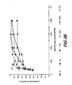
- Measured counting efficiency curves for the CNC are shown in the graphs in Figures 3A and 3B .
- the graphs show that the CNC can detect particles with at least 50% efficiency at particle sizes as small as 0.02 micrometer in thirteen different gases.
- Figure 3A shows the counter efficiency of the CNC for seven gases - - N 2 , CF 4 , C 2 F 6 , CHF 3 , SF 6 , He, and O 2.
- Figure 3B shows the counting efficiency of the CNC for six gases - - Ar, H 2 , NF 3 , N 2 O, NH 3 , and Cl 2 .
- the CNC 20 differs from previous attempts to obtain continuous counting of contaminant particles substantially smaller than 0.1 micrometer in process gases in that it is completely constructed from materials resistant to corrosion as well as reaction with oxidizing or flammable gases. Also, the CNC is designed to contain elevated pressures up to about 414 000 Pa (60 psig) and to prevent leakage of reactive or toxic gases under pressure. Since the CNC can contain sample gases at full gas line pressure, contaminant particles can be detected in the gas without upstream pressure reduction devices and the associated limitations of such devices, as discussed above.
Landscapes
- Chemical & Material Sciences (AREA)
- Health & Medical Sciences (AREA)
- Life Sciences & Earth Sciences (AREA)
- Pathology (AREA)
- General Physics & Mathematics (AREA)
- Immunology (AREA)
- Physics & Mathematics (AREA)
- Analytical Chemistry (AREA)
- Biochemistry (AREA)
- General Health & Medical Sciences (AREA)
- Dispersion Chemistry (AREA)
- Food Science & Technology (AREA)
- Medicinal Chemistry (AREA)
- Engineering & Computer Science (AREA)
- Sampling And Sample Adjustment (AREA)
- Investigating Or Analyzing Non-Biological Materials By The Use Of Chemical Means (AREA)
- Investigating Or Analysing Materials By Optical Means (AREA)
- Investigating Or Analyzing Materials By The Use Of Electric Means (AREA)
- Investigating Or Analyzing Materials By The Use Of Fluid Adsorption Or Reactions (AREA)
Claims (15)
- Dispositif pour la détection de particules dans un gaz contenant des particules dans un système de distribution de gaz contenant ledit gaz, comprenant:une ligne de distribution de gaz pour contenir ledit gaz; etun compteur de noyaux de condensation (20) en communication fluidique avec ladite ligne de distribution de gaz;caractérisé par les caractéristiques suivantes:la ligne de distribution de gaz et le compteur de noyaux de condensation sont adaptés pour supporter un gaz sous pression dont la pression peut être jusqu'à environ 414000 Pa supérieure à la pression atmosphérique (60 psig);le compteur de noyaux de condensation est connecté à ladite ligne de distribution de gaz de manière à recevoir un courant de gaz sous pression à une pression qui est sensiblement égale à la pression du gaz sous pression présent dans la ligne de distribution de gaz; etle compteur de noyaux de condensation est constitué à partir de matières qui résistent à la corrosion et à la réaction avec le gaz sous pression qui est sélectionné dans le groupe comprenant le SiCl4, le PH3, le B2H6, l'AsH3, le SiF4, le Si2H6, le NH3, le BCl3, le BF3, le Cl2, le H2, le HBr, le HCl, le HF, le NF3, le N2O, l'O2, le SiH4, le WF6, le N2, l'Ar, l'He, le CF4, le CHF3, le C2F6 et le SF6, ainsi que des mélanges de ceux-ci.
- Dispositif selon la revendication 1, comprenant en outre un moyen pour déterminer le nombre de particules dans le gaz sous pression.
- Dispositif selon la revendication 2, comprenant en outre un moyen pour tabuler le nombre de particules.
- Dispositif selon la revendication 3, dans lequel le moyen de tabulation est un ordinateur.
- Dispositif selon la revendication 1, dans lequel le compteur de noyaux de condensation (20) comprend:(a) un bloc de réservoir (26);(b) un tube d'entrée (22) adapté pour recevoir le courant du gaz sous pression et pour délivrer ledit courant dans le bloc de réservoir (26);(c) un saturateur (24) disposé à l'intérieur du bloc de réservoir (26), dans lequel le saturateur (24) est chauffé par un radiateur (30) qui est monté en contact thermique avec le bloc de réservoir (26);(d) un fluide de travail (28) disposé à l'intérieur du saturateur (24);(e) une mèche en métal fritté (32) partiellement submergée dans le fluide de travail (28);(f) un condenseur (34) adapté pour recevoir un courant du gaz sous pression en provenance du saturateur (24);(g) une buse de concentration aérodynamique (48) adaptée pour recevoir le courant de gaz sous pression contenant des gouttelettes;(h) une chambre de détection optique (44) comprenant un dispositif de détection de gouttelettes pour compter et identifier les gouttelettes dans le courant de gaz sous pression contenant des gouttelettes; et(i) un tube de sortie (56) adapté pour évacuer le courant de gaz sous pression contenant des gouttelettes hors de la chambre de détection optique (40).
- Procédé pour la détection de particules dans un gaz contenant des particules, comprenant les étapes:installer un dispositif selon l'une quelconque des revendications 1 à 5;introduire dans la ligne de distribution de gaz un gaz contenant des particules qui est pressurisé à une pression qui peut être jusqu'à environ 414000 Pa supérieure à la pression atmosphérique (60 psig); etintroduire un courant de gaz contenant des particules par l'intermédiaire de la ligne de distribution de gaz dans le compteur de noyaux de condensation à une pression qui est sensiblement égale à la pression du gaz sous pression dans la ligne de distribution de gaz.
- Procédé selon la revendication 6, comprenant en outre l'étape de déterminer le nombre de particules dans le gaz sous pression qui est introduit dans le compteur de noyaux de condensation (20).
- Procédé selon la revendication 7, comprenant en outre l'étape de tabuler le nombre de particules.
- Procédé selon la revendication 8, dans lequel on utilise un ordinateur pour réaliser la tabulation.
- Procédé selon la revendication 6, dans lequel les particules sont détectées avec un rendement de comptage d'au moins approximativement 50%.
- Procédé selon la revendication 6, dans lequel la pression est environ 414000 Pa supérieure à la pression atmosphérique (60 psig).
- Procédé selon la revendication 7, dans lequel l'étape de détermination du nombre de particules dans le gaz sous pression comprend les étapes secondaires:(a) faire passer le gaz contenant des particules mélangé avec un fluide de travail dans une zone de condensation;(b) condenser la vapeur de fluide de travail sur au moins une particule dans le gaz contenant des particules qui présente une taille minimum qui correspond à une température minimum d'une zone de condensation de manière à former au moins une gouttelette; et(c) détecter les gouttelettes et compter le nombre de gouttelettes en exécutant une détection et une tabulation appropriées.
- Procédé selon la revendication 12, dans lequel le fluide de travail est le perfluorotriméthylcyclohexane.
- Procédé selon la revendication 12, dans lequel le fluide de travail est un fluide non réactif.
- Procédé selon la revendication 14, dans lequel le fluide de travail non réactif est le fluide Multifluor®.
Applications Claiming Priority (2)
| Application Number | Priority Date | Filing Date | Title |
|---|---|---|---|
| US09/217,113 US6469780B1 (en) | 1998-12-21 | 1998-12-21 | Apparatus and method for detecting particles in reactive and toxic gases |
| US217113 | 1998-12-21 |
Publications (2)
| Publication Number | Publication Date |
|---|---|
| EP1014075A1 EP1014075A1 (fr) | 2000-06-28 |
| EP1014075B1 true EP1014075B1 (fr) | 2008-05-28 |
Family
ID=22809723
Family Applications (1)
| Application Number | Title | Priority Date | Filing Date |
|---|---|---|---|
| EP99124854A Expired - Lifetime EP1014075B1 (fr) | 1998-12-21 | 1999-12-15 | Procédé et dispositif pour la détection de particules dans des gaz réactifs et toxiques |
Country Status (9)
| Country | Link |
|---|---|
| US (1) | US6469780B1 (fr) |
| EP (1) | EP1014075B1 (fr) |
| JP (1) | JP3795718B2 (fr) |
| KR (1) | KR100346933B1 (fr) |
| AT (1) | ATE397205T1 (fr) |
| DE (1) | DE69938813D1 (fr) |
| ES (1) | ES2306496T3 (fr) |
| SG (1) | SG78406A1 (fr) |
| TW (1) | TWI232928B (fr) |
Families Citing this family (33)
| Publication number | Priority date | Publication date | Assignee | Title |
|---|---|---|---|---|
| KR100383547B1 (ko) * | 2000-09-25 | 2003-05-12 | 학교법인 한양학원 | 초미세입자 응축핵계수기 |
| US6639671B1 (en) * | 2002-03-01 | 2003-10-28 | Msp Corporation | Wide-range particle counter |
| US6829044B2 (en) * | 2002-04-24 | 2004-12-07 | Msp Corporation | Compact, high-efficiency condensation nucleus counter |
| US7214274B2 (en) * | 2003-03-17 | 2007-05-08 | Tokyo Electron Limited | Method and apparatus for thermally insulating adjacent temperature controlled processing chambers |
| US7342660B2 (en) * | 2003-09-25 | 2008-03-11 | Deka Products Limited Partnership | Detection system and method for aerosol delivery |
| US7867779B2 (en) * | 2005-02-03 | 2011-01-11 | Air Products And Chemicals, Inc. | System and method comprising same for measurement and/or analysis of particles in gas stream |
| US7537018B1 (en) * | 2005-05-03 | 2009-05-26 | Waters Investments Limited | Method and apparatus for controlling partial vapor pressure in a sorption analyzer |
| EP1924836B1 (fr) * | 2005-06-28 | 2017-11-29 | Koninklijke Philips N.V. | Capteur de particules ultrafines |
| US7777867B2 (en) * | 2006-12-22 | 2010-08-17 | Thermo Fisher Scientific | Devices, methods, and systems for detecting particles in aerosol gas streams |
| KR100895542B1 (ko) * | 2007-07-05 | 2009-05-06 | 안강호 | 응축핵 계수기 |
| WO2009117312A2 (fr) * | 2008-03-19 | 2009-09-24 | Waters Technologies Corporation | Appareil et procédés de fabrication de particules d’une substance à analyser |
| WO2010083513A2 (fr) * | 2009-01-16 | 2010-07-22 | University Of Cincinnati | Dispositifs de génération de gouttelettes en continu et procédés |
| DE102009001860A1 (de) * | 2009-03-25 | 2010-09-30 | Endress + Hauser Conducta Gesellschaft für Mess- und Regeltechnik mbH + Co. KG | Verfahren zum Bestimmen einer Anzahl von Tropfen |
| US8801838B2 (en) * | 2010-08-27 | 2014-08-12 | Aerosol Dynamics Inc. | Advanced laminar flow water condensation technology for ultrafine particles |
| US9579662B2 (en) | 2010-08-27 | 2017-02-28 | Aerosol Dynamics Inc. | Condensation-evaporator nanoparticle charger |
| US9610531B2 (en) | 2010-08-27 | 2017-04-04 | Aerosol Dynamics Inc. | Wick wetting for water condensation systems |
| RU2475721C2 (ru) * | 2011-04-27 | 2013-02-20 | Открытое акционерное общество "Электростальское научно-производственное объединение "Неорганика" (ОАО "ЭНПО "Неорганика") | Установка для измерения микропримесей в потоке газа |
| CN104678112A (zh) * | 2015-02-05 | 2015-06-03 | 中国科学院合肥物质科学研究院 | 一种串联差分电迁移率分析仪控制系统及控制方法 |
| TWI584344B (zh) * | 2015-08-12 | 2017-05-21 | 國立中山大學 | 可調式氣動聚焦構造 |
| JP6918806B2 (ja) * | 2016-01-08 | 2021-08-11 | ティーエスアイ インコーポレイテッド | ウェアラブル・マスク・フィット・モニタ |
| CN105865856B (zh) * | 2016-06-20 | 2018-07-27 | 国家电网公司 | 电气设备中sf6固体分解产物采集分析系统 |
| CN105954069B (zh) * | 2016-06-20 | 2018-07-27 | 国家电网公司 | 电气设备中sf6固体分解产物采样器 |
| AT519913B1 (de) * | 2017-05-03 | 2019-11-15 | Avl List Gmbh | Kondensationspartikelzähler mit Lichtleiter |
| AT519912B1 (de) * | 2017-05-03 | 2019-11-15 | Avl List Gmbh | Kondensationspartikelzähler mit Trennelement |
| US11029240B2 (en) | 2018-10-12 | 2021-06-08 | Aerosol Dynamics Inc. | Wick moisture sensor for airborne particle condensational growth systems |
| CN108535168B (zh) * | 2018-03-12 | 2023-11-28 | 清华大学 | 一种小型颗粒物冷凝生长计数器 |
| JP2021527198A (ja) | 2018-06-07 | 2021-10-11 | センサーズ インコーポレイテッド | 粒子濃度分析システム及び方法 |
| CN109116008A (zh) * | 2018-06-29 | 2019-01-01 | 南方电网科学研究院有限责任公司 | 一种c4f7n气体的毒性试验装置 |
| US11237091B2 (en) | 2018-11-01 | 2022-02-01 | Aerosol Dynamics Inc. | Humidity conditioning for water-based condensational growth of ultrafine particles |
| EP3835754A1 (fr) * | 2019-12-09 | 2021-06-16 | ETH Zurich | Procédé et dispositif de détermination de surface de particules |
| FR3123725A1 (fr) * | 2021-06-04 | 2022-12-09 | Valérie COMPAN | Dispositif mobile et autonome et procédé de detection d’analytes dans l’air |
| CN113720749B (zh) * | 2021-08-31 | 2023-01-17 | 北京航空航天大学 | 一种宽温纳米颗粒计数器 |
| CN114646578B (zh) * | 2022-03-17 | 2025-05-30 | 北京纳颗环境科技有限公司 | 一种便携式冷凝生长计数器 |
Family Cites Families (11)
| Publication number | Priority date | Publication date | Assignee | Title |
|---|---|---|---|---|
| US3632210A (en) | 1969-06-19 | 1972-01-04 | Environment One Corp | Variable rate continuous flow condensation nuclei meter having adjustable expansion period and improved gain |
| US3806248A (en) | 1973-02-21 | 1974-04-23 | Atomic Energy Commission | Continuous flow condensation nuclei counter |
| US4293217A (en) | 1980-02-06 | 1981-10-06 | The United States Of America As Represented By The Secretary Of The Army | Continuous-flow condensation nuclei counter and process |
| US4790650A (en) | 1987-04-17 | 1988-12-13 | Tsi Incorporated | Condensation nucleus counter |
| US5026155A (en) | 1989-09-06 | 1991-06-25 | Air Products And Chemicals, Inc. | Process for sizing particles using condensation nucleus counting |
| US5239356A (en) * | 1990-06-20 | 1993-08-24 | Fraunhofer-Gesellschaft Zur Forderung Der Angewandten Forschung Ev | Condensation nucleus counter |
| US5231865A (en) | 1992-01-02 | 1993-08-03 | Air Products And Chemicals, Inc. | Diffusion gas diluter |
| US5675405A (en) * | 1996-08-12 | 1997-10-07 | Met One, Inc. | Condensation nucleus counter employing supersaturation by thermal differentiation |
| US5872622A (en) * | 1996-08-12 | 1999-02-16 | Met One, Inc. | Condensation nucleus counter having vapor stabilization and working fluid recovery |
| US5659388A (en) * | 1996-09-11 | 1997-08-19 | Vlsi Standards, Inc. | Method and apparatus for operating a condensation nucleus counter with improved counting stability and accuracy over a variable detection threshold |
| US5903338A (en) * | 1998-02-11 | 1999-05-11 | Particle Measuring Systems, Inc. | Condensation nucleus counter using mixing and cooling |
-
1998
- 1998-12-21 US US09/217,113 patent/US6469780B1/en not_active Expired - Fee Related
-
1999
- 1999-12-14 KR KR1019990057455A patent/KR100346933B1/ko not_active Expired - Fee Related
- 1999-12-14 SG SG1999006360A patent/SG78406A1/en unknown
- 1999-12-15 DE DE69938813T patent/DE69938813D1/de not_active Expired - Fee Related
- 1999-12-15 EP EP99124854A patent/EP1014075B1/fr not_active Expired - Lifetime
- 1999-12-15 ES ES99124854T patent/ES2306496T3/es not_active Expired - Lifetime
- 1999-12-15 AT AT99124854T patent/ATE397205T1/de not_active IP Right Cessation
- 1999-12-16 TW TW088122177A patent/TWI232928B/zh not_active IP Right Cessation
- 1999-12-17 JP JP35899899A patent/JP3795718B2/ja not_active Expired - Fee Related
Also Published As
| Publication number | Publication date |
|---|---|
| ES2306496T3 (es) | 2008-11-01 |
| ATE397205T1 (de) | 2008-06-15 |
| TWI232928B (en) | 2005-05-21 |
| EP1014075A1 (fr) | 2000-06-28 |
| US6469780B1 (en) | 2002-10-22 |
| JP3795718B2 (ja) | 2006-07-12 |
| KR100346933B1 (ko) | 2002-07-31 |
| JP2000186994A (ja) | 2000-07-04 |
| KR20000052469A (ko) | 2000-08-25 |
| DE69938813D1 (de) | 2008-07-10 |
| SG78406A1 (en) | 2001-02-20 |
Similar Documents
| Publication | Publication Date | Title |
|---|---|---|
| EP1014075B1 (fr) | Procédé et dispositif pour la détection de particules dans des gaz réactifs et toxiques | |
| US5026155A (en) | Process for sizing particles using condensation nucleus counting | |
| US6686594B2 (en) | On-line UV-Visible light halogen gas analyzer for semiconductor processing effluent monitoring | |
| US20080137065A1 (en) | Measuring Analyte Concentrations in Liquids | |
| US5231865A (en) | Diffusion gas diluter | |
| WO2010139861A1 (fr) | Procédé et dispositif pour détecter des particules d'aérosol method and device for detecting aerosol particles | |
| US20070043520A1 (en) | Method for online measurement of ultrafine aggregate surface area and volume distributions | |
| US6892142B2 (en) | Method of analyzing particles suspended in liquid and liquid-suspended particle analyzer for carrying out the method | |
| JP3280464B2 (ja) | 被験液中の不揮発性残留物濃度監視装置及び同濃度測定方法 | |
| Wilson et al. | Investigation of volatile liquid surfaces by synchrotron x-ray spectroscopy of liquid microjets | |
| Wiederin et al. | Measurements of aerosol particle sizes from a direct injection nebulizer | |
| Chen et al. | Design and testing of an aerosol/sheath inlet for high resolution measurements with a DMA | |
| US4792199A (en) | System for detection of extremely small particles in a low pressure environment | |
| McMurry et al. | Particle beam mass spectrometer measurements of particle formation during low pressure chemical vapor deposition of polysilicon and SiO2 films | |
| JP2026501443A (ja) | エアロゾル粒子を肥大化するための方法、使用、デバイス、及びカートリッジ | |
| Takahara et al. | Particle analyzer system based on microwave-induced plasma technology | |
| McDermott et al. | A condensation nucleus counter for chemically reactive gases | |
| Tarik et al. | A practical guide on coupling a scanning mobility sizer and inductively coupled plasma mass spectrometer (smps-icpms) | |
| WO2001031312A2 (fr) | Procede de detection de nanoparticules | |
| Sem | Ultrafine (< 0.1− µm Diameter) Particles | |
| Poruthoor et al. | Automated particle collection and analysis. Near-real time measurement of aerosol cerium (III) | |
| Donovan | Off-Wafer Measurement of Contaminants | |
| Wang et al. | Counting particles in high-pressure electronic specialty gases | |
| Wicklund | Design and Fabrication of a Nanoelectrofluidic Experimental Cell | |
| Nijhawan | Experimental and computational study of particle nucleation, growth, and transport during low-pressure thermal decomposition of silane |
Legal Events
| Date | Code | Title | Description |
|---|---|---|---|
| PUAI | Public reference made under article 153(3) epc to a published international application that has entered the european phase |
Free format text: ORIGINAL CODE: 0009012 |
|
| AK | Designated contracting states |
Kind code of ref document: A1 Designated state(s): AT BE CH CY DE DK ES FI FR GB GR IE IT LI LU MC NL PT SE |
|
| AX | Request for extension of the european patent |
Free format text: AL;LT;LV;MK;RO;SI |
|
| 17P | Request for examination filed |
Effective date: 20000619 |
|
| AKX | Designation fees paid |
Free format text: AT BE CH CY DE DK ES FI FR GB GR IE IT LI LU MC NL PT SE |
|
| 17Q | First examination report despatched |
Effective date: 20050302 |
|
| GRAP | Despatch of communication of intention to grant a patent |
Free format text: ORIGINAL CODE: EPIDOSNIGR1 |
|
| GRAS | Grant fee paid |
Free format text: ORIGINAL CODE: EPIDOSNIGR3 |
|
| GRAA | (expected) grant |
Free format text: ORIGINAL CODE: 0009210 |
|
| AK | Designated contracting states |
Kind code of ref document: B1 Designated state(s): AT BE CH CY DE DK ES FI FR GB GR IE IT LI LU MC NL PT SE |
|
| REG | Reference to a national code |
Ref country code: GB Ref legal event code: FG4D |
|
| REG | Reference to a national code |
Ref country code: CH Ref legal event code: EP |
|
| REF | Corresponds to: |
Ref document number: 69938813 Country of ref document: DE Date of ref document: 20080710 Kind code of ref document: P |
|
| REG | Reference to a national code |
Ref country code: IE Ref legal event code: FG4D |
|
| PG25 | Lapsed in a contracting state [announced via postgrant information from national office to epo] |
Ref country code: FI Free format text: LAPSE BECAUSE OF FAILURE TO SUBMIT A TRANSLATION OF THE DESCRIPTION OR TO PAY THE FEE WITHIN THE PRESCRIBED TIME-LIMIT Effective date: 20080528 |
|
| REG | Reference to a national code |
Ref country code: ES Ref legal event code: FG2A Ref document number: 2306496 Country of ref document: ES Kind code of ref document: T3 |
|
| PG25 | Lapsed in a contracting state [announced via postgrant information from national office to epo] |
Ref country code: AT Free format text: LAPSE BECAUSE OF FAILURE TO SUBMIT A TRANSLATION OF THE DESCRIPTION OR TO PAY THE FEE WITHIN THE PRESCRIBED TIME-LIMIT Effective date: 20080528 |
|
| PG25 | Lapsed in a contracting state [announced via postgrant information from national office to epo] |
Ref country code: SE Free format text: LAPSE BECAUSE OF FAILURE TO SUBMIT A TRANSLATION OF THE DESCRIPTION OR TO PAY THE FEE WITHIN THE PRESCRIBED TIME-LIMIT Effective date: 20080828 Ref country code: PT Free format text: LAPSE BECAUSE OF FAILURE TO SUBMIT A TRANSLATION OF THE DESCRIPTION OR TO PAY THE FEE WITHIN THE PRESCRIBED TIME-LIMIT Effective date: 20081028 Ref country code: DK Free format text: LAPSE BECAUSE OF FAILURE TO SUBMIT A TRANSLATION OF THE DESCRIPTION OR TO PAY THE FEE WITHIN THE PRESCRIBED TIME-LIMIT Effective date: 20080528 |
|
| PGFP | Annual fee paid to national office [announced via postgrant information from national office to epo] |
Ref country code: NL Payment date: 20081111 Year of fee payment: 10 |
|
| PGFP | Annual fee paid to national office [announced via postgrant information from national office to epo] |
Ref country code: ES Payment date: 20081217 Year of fee payment: 10 |
|
| PGFP | Annual fee paid to national office [announced via postgrant information from national office to epo] |
Ref country code: IT Payment date: 20081216 Year of fee payment: 10 |
|
| PLBE | No opposition filed within time limit |
Free format text: ORIGINAL CODE: 0009261 |
|
| STAA | Information on the status of an ep patent application or granted ep patent |
Free format text: STATUS: NO OPPOSITION FILED WITHIN TIME LIMIT |
|
| PGFP | Annual fee paid to national office [announced via postgrant information from national office to epo] |
Ref country code: FR Payment date: 20081205 Year of fee payment: 10 |
|
| 26N | No opposition filed |
Effective date: 20090303 |
|
| PGFP | Annual fee paid to national office [announced via postgrant information from national office to epo] |
Ref country code: DE Payment date: 20081230 Year of fee payment: 10 |
|
| PGFP | Annual fee paid to national office [announced via postgrant information from national office to epo] |
Ref country code: GB Payment date: 20081110 Year of fee payment: 10 |
|
| PG25 | Lapsed in a contracting state [announced via postgrant information from national office to epo] |
Ref country code: MC Free format text: LAPSE BECAUSE OF NON-PAYMENT OF DUE FEES Effective date: 20081231 |
|
| PGFP | Annual fee paid to national office [announced via postgrant information from national office to epo] |
Ref country code: BE Payment date: 20090112 Year of fee payment: 10 |
|
| REG | Reference to a national code |
Ref country code: CH Ref legal event code: PL |
|
| PG25 | Lapsed in a contracting state [announced via postgrant information from national office to epo] |
Ref country code: LI Free format text: LAPSE BECAUSE OF NON-PAYMENT OF DUE FEES Effective date: 20081231 Ref country code: IE Free format text: LAPSE BECAUSE OF NON-PAYMENT OF DUE FEES Effective date: 20081215 Ref country code: CH Free format text: LAPSE BECAUSE OF NON-PAYMENT OF DUE FEES Effective date: 20081231 |
|
| BERE | Be: lapsed |
Owner name: AIR PRODUCTS AND CHEMICALS, INC. Effective date: 20091231 |
|
| PG25 | Lapsed in a contracting state [announced via postgrant information from national office to epo] |
Ref country code: LU Free format text: LAPSE BECAUSE OF NON-PAYMENT OF DUE FEES Effective date: 20081215 |
|
| REG | Reference to a national code |
Ref country code: NL Ref legal event code: V1 Effective date: 20100701 |
|
| PG25 | Lapsed in a contracting state [announced via postgrant information from national office to epo] |
Ref country code: CY Free format text: LAPSE BECAUSE OF FAILURE TO SUBMIT A TRANSLATION OF THE DESCRIPTION OR TO PAY THE FEE WITHIN THE PRESCRIBED TIME-LIMIT Effective date: 20080528 |
|
| GBPC | Gb: european patent ceased through non-payment of renewal fee |
Effective date: 20091215 |
|
| REG | Reference to a national code |
Ref country code: FR Ref legal event code: ST Effective date: 20100831 |
|
| PG25 | Lapsed in a contracting state [announced via postgrant information from national office to epo] |
Ref country code: NL Free format text: LAPSE BECAUSE OF NON-PAYMENT OF DUE FEES Effective date: 20100701 Ref country code: GR Free format text: LAPSE BECAUSE OF FAILURE TO SUBMIT A TRANSLATION OF THE DESCRIPTION OR TO PAY THE FEE WITHIN THE PRESCRIBED TIME-LIMIT Effective date: 20080829 Ref country code: FR Free format text: LAPSE BECAUSE OF NON-PAYMENT OF DUE FEES Effective date: 20091231 Ref country code: BE Free format text: LAPSE BECAUSE OF NON-PAYMENT OF DUE FEES Effective date: 20091231 |
|
| PG25 | Lapsed in a contracting state [announced via postgrant information from national office to epo] |
Ref country code: DE Free format text: LAPSE BECAUSE OF NON-PAYMENT OF DUE FEES Effective date: 20100701 |
|
| PG25 | Lapsed in a contracting state [announced via postgrant information from national office to epo] |
Ref country code: GB Free format text: LAPSE BECAUSE OF NON-PAYMENT OF DUE FEES Effective date: 20091215 |
|
| PG25 | Lapsed in a contracting state [announced via postgrant information from national office to epo] |
Ref country code: IT Free format text: LAPSE BECAUSE OF NON-PAYMENT OF DUE FEES Effective date: 20091215 |
|
| REG | Reference to a national code |
Ref country code: ES Ref legal event code: FD2A Effective date: 20110714 |
|
| PG25 | Lapsed in a contracting state [announced via postgrant information from national office to epo] |
Ref country code: ES Free format text: LAPSE BECAUSE OF NON-PAYMENT OF DUE FEES Effective date: 20110704 |
|
| PG25 | Lapsed in a contracting state [announced via postgrant information from national office to epo] |
Ref country code: ES Free format text: LAPSE BECAUSE OF NON-PAYMENT OF DUE FEES Effective date: 20091216 |