EP1014085A1 - Sonde de focalisation ultrasonique a ondes longitudinales destinee a l'inspection d'une matiere polymere, et systeme d'evaluation de defauts - Google Patents
Sonde de focalisation ultrasonique a ondes longitudinales destinee a l'inspection d'une matiere polymere, et systeme d'evaluation de defauts Download PDFInfo
- Publication number
- EP1014085A1 EP1014085A1 EP98941709A EP98941709A EP1014085A1 EP 1014085 A1 EP1014085 A1 EP 1014085A1 EP 98941709 A EP98941709 A EP 98941709A EP 98941709 A EP98941709 A EP 98941709A EP 1014085 A1 EP1014085 A1 EP 1014085A1
- Authority
- EP
- European Patent Office
- Prior art keywords
- end surface
- acoustic impedance
- test object
- flaw
- piezoelectric element
- Prior art date
- Legal status (The legal status is an assumption and is not a legal conclusion. Google has not performed a legal analysis and makes no representation as to the accuracy of the status listed.)
- Withdrawn
Links
- 239000000523 sample Substances 0.000 title claims abstract description 73
- 239000002861 polymer material Substances 0.000 title claims abstract description 26
- 238000011156 evaluation Methods 0.000 title description 3
- 230000007547 defect Effects 0.000 title 1
- 239000000463 material Substances 0.000 claims abstract description 108
- 238000012360 testing method Methods 0.000 claims abstract description 76
- 238000002592 echocardiography Methods 0.000 claims abstract description 50
- 238000007689 inspection Methods 0.000 claims abstract description 42
- 238000001514 detection method Methods 0.000 claims abstract description 36
- 229920000642 polymer Polymers 0.000 claims description 12
- 230000007704 transition Effects 0.000 claims description 12
- -1 polyethylene Polymers 0.000 description 59
- 239000004698 Polyethylene Substances 0.000 description 56
- 229920000573 polyethylene Polymers 0.000 description 56
- 230000004927 fusion Effects 0.000 description 9
- 229920005672 polyolefin resin Polymers 0.000 description 9
- XLYOFNOQVPJJNP-UHFFFAOYSA-N water Substances O XLYOFNOQVPJJNP-UHFFFAOYSA-N 0.000 description 9
- 229910044991 metal oxide Inorganic materials 0.000 description 7
- 230000002093 peripheral effect Effects 0.000 description 6
- 238000010276 construction Methods 0.000 description 4
- 229910052751 metal Inorganic materials 0.000 description 4
- 239000002184 metal Substances 0.000 description 4
- 230000001360 synchronised effect Effects 0.000 description 4
- 239000007822 coupling agent Substances 0.000 description 3
- 229920003020 cross-linked polyethylene Polymers 0.000 description 3
- 239000004703 cross-linked polyethylene Substances 0.000 description 3
- 238000002474 experimental method Methods 0.000 description 3
- 238000005259 measurement Methods 0.000 description 3
- 238000000034 method Methods 0.000 description 3
- 239000010409 thin film Substances 0.000 description 3
- 239000011800 void material Substances 0.000 description 3
- BQCIDUSAKPWEOX-UHFFFAOYSA-N 1,1-Difluoroethene Chemical compound FC(F)=C BQCIDUSAKPWEOX-UHFFFAOYSA-N 0.000 description 2
- PEDCQBHIVMGVHV-UHFFFAOYSA-N Glycerine Chemical compound OCC(O)CO PEDCQBHIVMGVHV-UHFFFAOYSA-N 0.000 description 2
- 239000002033 PVDF binder Substances 0.000 description 2
- 229910000831 Steel Inorganic materials 0.000 description 2
- 230000004323 axial length Effects 0.000 description 2
- 229920001577 copolymer Polymers 0.000 description 2
- 238000012937 correction Methods 0.000 description 2
- 230000002950 deficient Effects 0.000 description 2
- 238000010586 diagram Methods 0.000 description 2
- 239000000428 dust Substances 0.000 description 2
- 230000005284 excitation Effects 0.000 description 2
- 239000010408 film Substances 0.000 description 2
- 238000010438 heat treatment Methods 0.000 description 2
- HFGPZNIAWCZYJU-UHFFFAOYSA-N lead zirconate titanate Chemical compound [O-2].[O-2].[O-2].[O-2].[O-2].[Ti+4].[Zr+4].[Pb+2] HFGPZNIAWCZYJU-UHFFFAOYSA-N 0.000 description 2
- 229910052451 lead zirconate titanate Inorganic materials 0.000 description 2
- GQYHUHYESMUTHG-UHFFFAOYSA-N lithium niobate Chemical compound [Li+].[O-][Nb](=O)=O GQYHUHYESMUTHG-UHFFFAOYSA-N 0.000 description 2
- 238000004519 manufacturing process Methods 0.000 description 2
- 238000000465 moulding Methods 0.000 description 2
- 229920003023 plastic Polymers 0.000 description 2
- 239000004033 plastic Substances 0.000 description 2
- 229920001083 polybutene Polymers 0.000 description 2
- 229920002981 polyvinylidene fluoride Polymers 0.000 description 2
- 239000000843 powder Substances 0.000 description 2
- 239000004576 sand Substances 0.000 description 2
- 239000010959 steel Substances 0.000 description 2
- 238000013459 approach Methods 0.000 description 1
- 230000005540 biological transmission Effects 0.000 description 1
- UUAGAQFQZIEFAH-UHFFFAOYSA-N chlorotrifluoroethylene Chemical group FC(F)=C(F)Cl UUAGAQFQZIEFAH-UHFFFAOYSA-N 0.000 description 1
- 230000003111 delayed effect Effects 0.000 description 1
- 230000006866 deterioration Effects 0.000 description 1
- 230000000694 effects Effects 0.000 description 1
- 235000011187 glycerol Nutrition 0.000 description 1
- 238000007654 immersion Methods 0.000 description 1
- 239000003973 paint Substances 0.000 description 1
- 230000001902 propagating effect Effects 0.000 description 1
- 229920005989 resin Polymers 0.000 description 1
- 239000011347 resin Substances 0.000 description 1
- BFKJFAAPBSQJPD-UHFFFAOYSA-N tetrafluoroethene Chemical group FC(F)=C(F)F BFKJFAAPBSQJPD-UHFFFAOYSA-N 0.000 description 1
Images




Classifications
-
- G—PHYSICS
- G01—MEASURING; TESTING
- G01N—INVESTIGATING OR ANALYSING MATERIALS BY DETERMINING THEIR CHEMICAL OR PHYSICAL PROPERTIES
- G01N29/00—Investigating or analysing materials by the use of ultrasonic, sonic or infrasonic waves; Visualisation of the interior of objects by transmitting ultrasonic or sonic waves through the object
- G01N29/22—Details, e.g. general constructional or apparatus details
- G01N29/24—Probes
- G01N29/2437—Piezoelectric probes
-
- G—PHYSICS
- G01—MEASURING; TESTING
- G01N—INVESTIGATING OR ANALYSING MATERIALS BY DETERMINING THEIR CHEMICAL OR PHYSICAL PROPERTIES
- G01N29/00—Investigating or analysing materials by the use of ultrasonic, sonic or infrasonic waves; Visualisation of the interior of objects by transmitting ultrasonic or sonic waves through the object
- G01N29/22—Details, e.g. general constructional or apparatus details
- G01N29/24—Probes
- G01N29/2456—Focusing probes
-
- G—PHYSICS
- G01—MEASURING; TESTING
- G01N—INVESTIGATING OR ANALYSING MATERIALS BY DETERMINING THEIR CHEMICAL OR PHYSICAL PROPERTIES
- G01N29/00—Investigating or analysing materials by the use of ultrasonic, sonic or infrasonic waves; Visualisation of the interior of objects by transmitting ultrasonic or sonic waves through the object
- G01N29/22—Details, e.g. general constructional or apparatus details
- G01N29/24—Probes
- G01N29/2468—Probes with delay lines
-
- G—PHYSICS
- G01—MEASURING; TESTING
- G01N—INVESTIGATING OR ANALYSING MATERIALS BY DETERMINING THEIR CHEMICAL OR PHYSICAL PROPERTIES
- G01N29/00—Investigating or analysing materials by the use of ultrasonic, sonic or infrasonic waves; Visualisation of the interior of objects by transmitting ultrasonic or sonic waves through the object
- G01N29/22—Details, e.g. general constructional or apparatus details
- G01N29/28—Details, e.g. general constructional or apparatus details providing acoustic coupling, e.g. water
-
- G—PHYSICS
- G01—MEASURING; TESTING
- G01N—INVESTIGATING OR ANALYSING MATERIALS BY DETERMINING THEIR CHEMICAL OR PHYSICAL PROPERTIES
- G01N29/00—Investigating or analysing materials by the use of ultrasonic, sonic or infrasonic waves; Visualisation of the interior of objects by transmitting ultrasonic or sonic waves through the object
- G01N29/36—Detecting the response signal, e.g. electronic circuits specially adapted therefor
- G01N29/38—Detecting the response signal, e.g. electronic circuits specially adapted therefor by time filtering, e.g. using time gates
-
- G—PHYSICS
- G01—MEASURING; TESTING
- G01N—INVESTIGATING OR ANALYSING MATERIALS BY DETERMINING THEIR CHEMICAL OR PHYSICAL PROPERTIES
- G01N2291/00—Indexing codes associated with group G01N29/00
- G01N2291/02—Indexing codes associated with the analysed material
- G01N2291/023—Solids
- G01N2291/0231—Composite or layered materials
-
- G—PHYSICS
- G01—MEASURING; TESTING
- G01N—INVESTIGATING OR ANALYSING MATERIALS BY DETERMINING THEIR CHEMICAL OR PHYSICAL PROPERTIES
- G01N2291/00—Indexing codes associated with group G01N29/00
- G01N2291/02—Indexing codes associated with the analysed material
- G01N2291/023—Solids
- G01N2291/0235—Plastics; polymers; soft materials, e.g. rubber
-
- G—PHYSICS
- G01—MEASURING; TESTING
- G01N—INVESTIGATING OR ANALYSING MATERIALS BY DETERMINING THEIR CHEMICAL OR PHYSICAL PROPERTIES
- G01N2291/00—Indexing codes associated with group G01N29/00
- G01N2291/04—Wave modes and trajectories
- G01N2291/042—Wave modes
- G01N2291/0421—Longitudinal waves
-
- G—PHYSICS
- G01—MEASURING; TESTING
- G01N—INVESTIGATING OR ANALYSING MATERIALS BY DETERMINING THEIR CHEMICAL OR PHYSICAL PROPERTIES
- G01N2291/00—Indexing codes associated with group G01N29/00
- G01N2291/04—Wave modes and trajectories
- G01N2291/042—Wave modes
- G01N2291/0422—Shear waves, transverse waves, horizontally polarised waves
Definitions
- This invention relates to a focus type longitudinal wave ultrasonic probe and an ultrasonic flaw evaluating apparatus for use in an ultrasonic flaw detection to perform a nondestructive inspection by transmitting ultrasonic wave to a test object such as a polymer material, and evaluating echoes reflected from flaws and the like.
- a polymer material and the like generally, have a greater factor of sound wave attenuation than metal such as steel, and provide only detection signals of low S/N ratio when an ordinary ultrasonic probe is used. Lowering the frequency of ultrasonic beams to reduce a loss due to attenuation results in a deterioration in flaw resolution.
- the focus type longitudinal wave ultrasonic probe includes a fixed focus type having a curved piezoelectric element acting as an ultrasonic transducer (or a plurality of piezoelectric element pieces arranged in a curve to form a curved piezoelectric element) to focus ultrasonic beams at a predetermined propagation distance, and an electronic focus type having a plurality of piezoelectric elements arranged in a scanning direction, each of which is oscillated with a slight delay to give directivity to ultrasonic beams to focus an ultrasonic beam composed thereof at a desired propagation distance.
- the electronic focus type has a complicated control circuit, and the probe itself is very precise and must be handled with care. This type is used chiefly for ultrasonic diagnostic apparatus in sites of medical treatment.
- the fixed focus type is used in material inspection and the like.
- the fixed focus type probe has a matching material formed on a front surface of the curved piezoelectric element with a forward end surface of the matching material placed in contact with the surface of a test object.
- Ultrasonic waves excited by the curved piezoelectric element are transmitted through the matching material into the test object.
- a reflection of the ultrasonic waves occurs between the curved piezoelectric element and the matching material and between the matching material and the surface of the test object. Not only does this reflection bring about a loss of sound wave energy but a repetition of reflection echo obstructs a flaw detection.
- One object of this invention is to reduce such a disadvantage from a focus type longitudinal wave ultrasonic probe which uses a curved piezoelectric element.
- Another object of this invention is to provide an improved flaw evaluating apparatus for an ultrasonic flaw detecting apparatus used in an ultrasonic flaw detection of joints of polymer pipes as noted hereinbefore. That is, in order to evaluate a flaw existing in a test object, a conventional ultrasonic flaw detecting apparatus is constructed to select only an echo from the flaw by gating a region excluding a time base region with echoes occurring due to shapes of a test object such as a surface echo and a bottom echo. That is, a position and width of a flaw detecting gate are determined to satisfy a range of flaw detection, in time of scanning the test object with the ultrasonic probe, by a geometrical calculation based on positions of the ultrasonic probe.
- a gate circuit employs a surface echo synchronized gate mode to synchronize to the surface echo of the test object and to set a flaw detecting gate based thereon, or an excitation pulse synchronized gate mode to set a flaw detecting gate based on a synchronization signal the pulses for exciting ultrasonic waves, thereby to evaluate echoes returning from inside the test object constantly as flaw echoes.
- a flaw evaluating apparatus for an ultrasonic flaw detecting apparatus where reflection sources which are not flaws exist in the test object an ultrasonic propagation time region of the reflection sources is removed from the flaw gate to exclude the echoes from the reflection sources from the flow echoes. In this case, it is impossible to detect flaws existing in the same ultrasonic propagation time region as the reflection sources.
- Another object of this invention here is to provide a flaw evaluating apparatus for covering a desired range of flaw detection even where reflection sources which are not flaws exist in a test object inspected by an ultrasonic flaw detecting apparatus.
- a focus type longitudinal wave ultrasonic probe for polymer material inspection comprising a curved piezoelectric element and a matching material having an input end surface in close contact with a concave surface of said curved piezoelectric element and an output end surface for fitting to a surface of a polymer material acting as a test object wherein said matching material has an acoustic impedance matched to an acoustic impedance of said test object.
- the reflection of ultrasonic wave at the boundary between the matching material and the surface of the test object may be suppressed. That is, an energy loss of the ultrasonic wave entering the test object from the matching material may be reduced.
- the flaw detection is carried out with a reduced chance of obstruction by repetition of reflection echoes. A flaw detection signal of excellent S/N ratio is obtained even in an inspection of a material with a high degree of ultrasonic attenuation.
- a focus type longitudinal wave ultrasonic probe for polymer material inspection comprising a curved piezoelectric element, and a matching material having an input end surface in dose contact with a concave surface of said curved piezoelectric element and an output end surface for fitting to a surface of a polymer material acting as a test object, wherein said matching material has an acoustic impedance matched to an acoustic impedance of said curved piezoelectric element.
- the characteristics of ultrasonic propagation from the curved piezoelectric element to the matching material are improved by matching the acoustic impedance of the matching material to the acoustic impedance of the curved piezoelectric element, As in the case of the foregoing ultrasonic probe, a flaw detection signal of excellent S/N ratio is obtained even in an inspection of a material with a high degree of ultrasonic attenuation.
- a focus type longitudinal wave ultrasonic probe having the above two characterizing features i.e. an ultrasonic probe in which the matching material has an acoustic impedance matched to the acoustic impedance of the test object, and the matching material has an acoustic impedance matched to the acoustic impedance of the curved piezoelectric element of course provides still more excellent inspection results.
- a piezoelectric element used in the field of ultrasonic flaw detection usually, is formed of a piezoelectric metallic oxide such as lead zirconate titanate, lead niobate or lithium niobate.
- a high level of skill is required to make a curved piezoelectric element for a fixed focus type probe.
- a piezoelectric metallic oxide has a relatively large acoustic impedance.
- the curved piezoelectric element is formed of a polymer piezoelectric material.
- the focus type longitudinal wave ultrasonic probe is made only by putting a sheet-like polymer material, with thin film electrodes applied thereto, in close contact with a convex end of the matching material acting as an ultrasonic propagation member.
- the acoustic impedance of the matching material may easily be assimilated to the acoustic impedance of the polymer piezoelectric element. Consequently sound wave reflection and sound field disturbance at the boundary surface are remarkably suppressed, compared with a metallic oxide and plastic.
- a range of similarity in acoustic impedance between the matching material and polymer piezoelectric element is, herein, a range including differences in acoustic impedance therebetween which satisfy a condition that sound wave reflection and sound field disturbance occurring at the boundary therebetween do not affect a flaw detection requiring high resolution. It has been found through experiment that differences in acoustic impedance of about 1 - 3 times are adequate. Such differences in acoustic impedance are regarded as falling within the range of similarity between the acoustic impedance of the matching material and the acoustic impedance of said curved piezoelectric element in this invention. These differences may be said extremely small compared with the difference between a piezoelectric metallic oxide and plastic which generally is ten times or more.
- the acoustic impedance of the matching material varies from a value matching the acoustic impedance of said curved piezoelectric element toward a value matching the acoustic impedance of said test object, with respect to a direction of propagation from said input end surface to the output end surface of a longitudinal ultrasonic wave launched by the curved piezoelectric element.
- the characteristics of ultrasonic propagation from the piezoelectric element to the matching material are improved.
- the acoustic impedance of the matching material is similar to the acoustic impedance of the test object.
- the matching material having acoustic impedance variations may be realized by a centrifugal molding carried out while adding a metal powder of high acoustic impedance to a polymer material, or by stacking a plurality of polymer sheets different in acoustic impedance.
- a length of the matching material such that a longitudinal ultrasonic wave launched from the curved piezoelectric element converges at predetermined inspection point in the test object.
- the fixed focus type probe has a fixed focal length determined by the curved shape of the piezoelectric element, a range for providing clear echoes of high resolution is limited. It is therefore necessary to manufacture a probe for each distance from the material surface to a flaw detection region.
- a probe must be manufactured which defines a contact surface matched to a surface curvature in order to secure an excellent contact between the probe and the test object.
- a considerable number of focus type probes are usually needed.
- the matching material is divided into a first matching material and a second matching material, the first matching material having one end surface thereof formed as the input end surface, and the other end surface formed as a first transition end surface, the second matching material having one end surface thereof formed as the output end surface, and the other end surface formed as a second transition end surface for close contact with the first transition end surface, the first transition end surface having an acoustic impedance matched to an acoustic impedance of the second transition end surface.
- the matching material lying between the curved piezoelectric element and the test object is formed of two parts, i.e. the first matching material and second matching material.
- a focal paint formed in the test object is adjusted by the length of the second matching material.
- the acoustic impedances of the first transition end surface and second transition end surface, i.e. the acoustic impedances of the boundary region between the first matching material and second matching material are assimilated, thereby to suppress also echoes occurring from the interface between the first matching material and second matching material.
- the statement that the first matching material and second matching material have an equal acoustic impedance should include a range for causing echoes to occur from the interface therebetween only to the extent of not affecting evaluation of a flaw echo.
- the focus type longitudinal wave ultrasonic probe of this invention requires only a different second matching material for each test object even where various test objects are inspected.
- the second matching material is attachable to and detachable from the first matching material. Then, an optimal focus type longitudinal wave ultrasonic probe is completed only by selecting a best suited one from among a plurality of second matching materials made to suit various test objects, and attaching it to a single sub-assembly consisting of the curved piezoelectric element and the first matching material.
- the cost of inspection may be reduced dramatically compared with the prior art.
- An important inspection using the focus type longitudinal wave ultrasonic probe of this invention is an ultrasonic inspection of a fused location of a polyolefin resin pipe EF (heat fused) joint.
- a fused part formed between an inner peripheral surface of the joint having a fusing wire mounted in the joint and wound helically in the axial direction, and outer peripheral surfaces of pipes fused to the fusion joint is inspected by propagating ultrasonic beams to pass through gaps formed by the wire.
- the curved shape of the surface with which the probe is placed in contact and the depth to the wire are different depending on the type of pipe.
- the first matching material and second matching material are formed of a polyolefin resin.
- polyolefin resins are polyethylene and crosslinked polyethylene, and polybutene may also be used.
- a flaw evaluating apparatus comprising a first gate circuit for generating a first gate for an echo from a predetermined reflection source in said test object, a second gate circuit for generating a second gate for flaw detection in a position of a predetermined time delay from said first echo, a first evaluating circuit for determining that a flaw has been detected when an amplitude of said first echo exceeds a predetermined level, and a second evaluating circuit for determining that a flaw has been detected when an echo occurs at said second gate.
- the first gate is set to an ultrasonic propagation time region of echoes occurring from a reflection source which is not a flaw
- the second gate is set to other flaw detection regions.
- a signal of a level exceeding the strength of an echo usually occurring from a reflection source which is not a flaw is evaluated as indicating a flaw.
- An echo occurring to the second gate is evaluated as indicating a flaw.
- a desired range of flaw detection may be covered, including regions having reflection sources which are not flaws.
- said second gate circuit is operable to vary an interval time between said first echo and said second gate following a variation in sound velocity in said test object.
- This embodiment provides an advantage of no longer requiring an imperative that sound velocity in the test object is fixed when gates are generated in the surface echo synchronized gate mode or excitation pulse synchronized gate mode noted hereinbefore. This is a great advantage in a flaw detection carried out after a heat process, such as fusion joining, of materials having a sound velocity greatly variable with heat.
- a gate may be generated to correspond accurately to a desired region in the test object.
- the first gate circuit is operable to vary an interval time between a surface echo and the first gate following a variation in sound velocity in the test object
- the second gate circuit is operable to vary an interval time between the first echo and second gate following the variation in sound velocity in the test object.
- a sound velocity at that point of time must be grasped.
- a variation in sound velocity in the test object is determined by measuring an interval time between echoes from two predetermined reflection sources in the test object e.g. a surface echo and a bottom echo. Take an ultrasonic inspection of a fused location of a polyolefin resin pipe EF (heat fused) joint, as a typical example of application of an ultrasonic flaw detecting apparatus having the flaw evaluating apparatus according to this invention.
- EF heat fused
- a fused part formed between an inner peripheral surface of the joint having a fusing wire mounted in the joint and wound helically in the axial direction, and outer peripheral surfaces of pipes fused to the fusing joint is inspected.
- the first gate may be set to a wire region, and the second gate to a fused surface region, to use an echo from the wire and an echo from an inner surface of the pipe as echoes from the predetermined reflection sources.
- a focus type longitudinal wave ultrasonic probe 1 is used in an ultrasonic inspection of a connecting state of a polyethylene pipe EF joint 3 butt-joining two polyethylene pipes 2.
- Polyethylene is employed here as one material included in polyolefin resins.
- power is fed to a fusing wire 4 wound axially and helically in an inner wall to heat it and fuse adjacent regions, thereby fusing together inner wall surfaces 3b of polyethylene pipe EF joint 3 and outer wall surfaces 2a of polyethylene pipes 2, to achieve a strong sealed connection.
- an unfused part 5 occurs when, for example, sand, dust, dirt, water, muddy water or the like enters between the inner wall surfaces 3b of polyethylene pipe EF joint 3 and outer wall surfaces 2a of polyethylene pipes 2,
- the focus type longitudinal wave ultrasonic probe 1 is used to find such unfused part 5 from an outer wall surface 3a of polyethylene pipe EF joint 3.
- the fusing wire 4 is wound helically in the direction of a pipe axis, it is important to inspect a fused region with ultrasonic beams having sound axis lines passing through gaps of fusing wire 4, so that echoes from the fusing wire 4 would not obstruct detection of an echo from the unfused part 5. That is, the inspection needs to be carried out with ultrasonic beams of high resolution.
- the focus type longitudinal wave ultrasonic probe 1 must focus from the fusing wire 4 between the fused region.
- This focus type longitudinal wave ultrasonic probe 1 includes a curved piezoelectric element 11 backed by a damper material 13, a matching material 12 in close contact with a front surface or concave surface of piezoelectric element 11, and a cup-like main case 14 housing these integrated components.
- a material of piezoelectric element 11 a polymer piezoelectric film is selected according to specifications, typical examples of which include polydifluoroethylene (polyvinylidene fluoride: PVDF), P (VDF-TrFE) (copolymer of vinylidene fluoride and trifluorochloroethylene) and P (VDF-TeFE) (copolymer of vinylidene fluoride and tetrafluoroethylene).
- the focus type longitudinal wave ultrasonic probe 1 acts as an ultrasonic transmitter/receiver for ultrasonic flaw detection.
- the matching material 12 is formed of polyethylene which is the same material as the test object, and a surface thereof remote from the piezoelectric element 11 is recessed to fit to the outer wall surface 3a of polyethylene pipe EF joint 3. Consequently, excellent adhesion is secured only by applying a thin coupling agent 6 between the matching material 12 and the outer wall surface 3a.
- This focus type longitudinal wave ultrasonic probe 1 has a focal length variable as desired by varying the length of matching material 12.
- the piezoelectric element 11 used here has an acoustic impedance of 2.1 ⁇ 10 6 kg/s ⁇ m 2 .
- the matching material 12 formed of polyethylene has an acoustic impedance of 4.5 ⁇ 10 6 kg/s ⁇ m 2 .
- Fig. 3 shows a sound pressure state of this focus type longitudinal wave ultrasonic probe 1 measured by immersion testing (aiming at a blade of 0.34mm in thickness), which proves that an excellent focus level is secured. Further, Fig.
- FIG. 4 shows positions of probe 1 relative to a test piece for inspecting a connecting state of the above-mentioned polyethylene pipe EF joint 3, and echoes displayed on a monitor.
- This test piece has an unfused part artificially formed in a joining portion disposed inwardly of the wire 4 of polyethylene pipe EF joint 3.
- echoes from the wire 4 should occur with rises and falls adjacent a position of 16 ⁇ sec propagation time, and echoes of the artificial flaw (location of defective joint) adjacent a position of 18 ⁇ sec propagation time.
- the vertical axis represents ultrasonic amplitude (voltage) while the horizontal axis represents ultrasonic propagation time.
- the propagation time is shown covering only a region of 7 ⁇ sec to 27 ⁇ sec, with a substantial region for flaw detection located in the center.
- the matching material 12 may be formed of a material with gradient acoustic impedance characteristics to approach the acoustic impedance of the test object from the acoustic impedance of polymer piezoelectric element 11, which is advantageous for flaw inspection since boundary echoes are reduced at the boundary with the test object.
- Manufacture of the matching material having acoustic impedance variations is selected based on a material used.
- What is proposed is a method of centrifugal molding carried out while adding a metal powder of high acoustic impedance to a polymer material, or a method of stacking a plurality of polymer sheets different in acoustic impedance.
- This focus type longitudinal wave ultrasonic probe 1 includes a main body 10, and a sub-body 20 selectively changeably connected to the main body 10. That is, the sub-body 20 is detachably attached to a lower portion of the probe in the preceding embodiment.
- a matching material 12 here is divided into a first member 12 mounted in the main body 10 and a second member 21 mounted in the sub-body 20.
- the main body 10 includes a curved piezoelectric element 11 backed by a damper material 13, a first matching material 12 in close contact with a front surface or concave surface of piezoelectric element 11, and a cup-like main case 14 housing these integrated components.
- Thin film electrodes, not shown, formed on the piezoelectric element 11 are connected through electric wires 15 to a connector 16 attached to the main case 14.
- the first member 12, also here, is formed of polyethylene which is the same material as the test object, and a surface thereof remote from the piezoelectric element 11 is finished precisely flat and slightly protrudes from an end surface of the main case 14.
- the sub-body 20 includes the second member 21, and a sub-case 22 surrounding the second member 21.
- the second member 21 also is formed of polyethylene which is the same as the first member 12, and a surface thereof in close contact with the first member 12 is finished precisely flat while the other surface is recessed to fit to the outer wall surface 3a of polyethylene pipe EF joint 3 acting as a scan surface.
- a female screw 22a formed on an inner wall surface of sub-case 22 is meshed with a male screw 14a formed on an outer wall surface of main case 14, to integrate the main case 14 and sub-case 22, with the first member 12 and second member 21 placed in end-to-end contact with each other.
- a coupling agent such as glycerin
- the focus type longitudinal wave ultrasonic probe 1 is completed by assembling the sub-case 22 to the main case 14, and has a focal length variable as desired by varying the length of the second member 21 in the sub-body 20. That is, as seen from Fig. 5, the first matching material 12 has a fixed axial length: L1, the second matching material 21 has an axial length: L2 variable with the sub-body 20 to be selected, and the piezoelectric element 11 has a focal length: L determined by the shape of the curved surface. Consequently, a focal point may be set to a fused region of the polyethylene pipe EF joint 3 by selecting a sub-body 20 with a second matching material 21 having an appropriate length: L2.
- the sub-body 20 it is also important to select one that has the surface, opposed to the test object, of the second member 21 fitting to the outer wall surface 3a of polyethylene pipe EF joint 3. Consequently, excellent adhesion is secured only by applying a thin coupling agent 6 between the second member 21 and the outer wall surface 3a.
- the focus type longitudinal wave ultrasonic probe 1 shown in Fig. 6 has a short sub-body 20 attached.
- the focus type longitudinal wave ultrasonic probe 1 in this embodiment it is important that the first member 12 and second member 21 act for matching of the focal length, and also for matching of the acoustic impedance to avoid boundary echoes occurring at the boundary therebetween which would obstruct determination of a flaw.
- a polymer piezoelectric film is used as the piezoelectric element 11.
- a piezoelectric metallic oxide such as lead zirconate titanate, lead niobate or lithium niobate may be employed.
- the first important point of this invention is that, in the focus type longitudinal wave ultrasonic probe 1, the piezoelectric element 11, matching material and test object 3 have appropriately selected acoustic impendances.
- the above piezoelectric element 11 has a spherical, curved shape, which is known as the point focus type. This may be replaced with the line focus type having a cylindrical, curved shape which also falls within the scope of this invention.
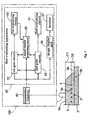
- Fig. 7 is a block diagram of an ultrasonic flaw detecting apparatus 100 having a flaw evaluating apparatus 50 according to this invention.
- the ultrasonic flaw detecting apparatus 100 transmits ultrasonic waves to a test object through the ultrasonic probe 1, and evaluates returning echoes.
- the apparatus is used in an ultrasonic inspection of a connecting state of a polyethylene pipe EF (heat fused) joint 3 butt-joining two polyethylene pipes 2.
- echoes occur from the fusing wire 4 when the fusing wire 4 lies on ultrasonic beams from the ultrasonic probe 1.
- echoes from the unfused part 5 are of course detected as flaw echoes.
- echoes from a void 5a formed adjacent the fusing wire 4 as a result for example, of heating of water or muddy water having entered between the inner wall surface 3b and outer wall surface 2a as noted above occur as overlapping the echoes from the fusing wire 4.
- the flaw evaluating apparatus 50 includes a first gate circuit 51 and second gate circuit 52, a first evaluating circuit 53 and second evaluating circuit 54, and further a sound velocity evaluating circuit 55 for evaluating a sound velocity of polyethylene pipe EF joint 3 which is the test object.
- a first gate 31 generated by the first gate circuit 51 and a second gate 32 generated by the second gate circuit 52 are displayed by an image display unit 56 on a monitor 57 along with echoes occurring as the case may be. Echoes from the fusing wire 4 and echoes from the void 5a are detected by the first gate 31, and echoes from the unfused part 5 by the second gate 32.
- the echoes detected by the first gate 31 are transmitted as electric signals to the first evaluating circuit 53, and compared with a predetermined threshold to determine whether they are flaw echoes from the void 5a formed adjacent the fusing wire 4 as a result, for example; of heating of water or muddy water having entered between the inner wall surface 3b and outer wall surface 2a. That is, since the echoes returning after being directly reflected from the fusing wire 4 have an amplitude that can be guessed beforehand, echoes exceeding it are determined to be flaw echoes.
- the echoes detected by the second gate 32 are transmitted as electric signals to the second evaluating circuit 54.
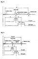
- Fig. 8 shows a monitor screen displaying the flaw echoes detected by the first gate 31, and a scanning position of ultrasonic probe 1 at this time.
- Fig. 9 shows a monitor screen displaying the flaw echoes detected by the second gate 32, and a scanning position of ultrasonic probe 1 at this time.
- point 0 on the horizontal axis or ultrasonic propagation time axis does not correspond to a transmission pulse position, but to an appropriate position selected for easiness in viewing the monitor screen.
- the gates are set to a time axis region corresponding to a flaw occurring region in a test object. This is done on the condition that sound velocity in the test object is constant.
- the inspection is performed immediately after thermal fusion takes place. Material temperature varies every moment throughout an inspecting operation, resulting in variations in the sound velocity. It is therefore necessary to vary gate positions following the variations in the sound velocity in order to obtain accurate gate positions.
- the ultrasonic probe 1 scans the outer wall surface 3a of polyethylene pipe EF joint 3 and injects an ultrasonic wave
- an echo from the fusing wire 4 present at a distance: D1 from the outer wall surface 3a occurs in a position at a time: t1 from a surface echo.
- the first gate 31 is set with a duration 2 ⁇ from t1- ⁇ to t1+ ⁇ .
- an unfused flaw region is present between the inner wall surface 3b of polyethylene pipe EF joint 3 and the outer wall surface 2a of polyethylene pipe 2, at a distance: D2 from the fusing wire 4.
- the second gate 32 is set with a duration 2 ⁇ from t1+t2- ⁇ to t1+t2+ ⁇ .
- a dummy surface echo position may be determined from a transmitted pulse to serve as a reference for the gate setting.
- Fig 10 schematically shows a way in which these gates are set.
- the sound velocity evaluating circuit 52 detects the surface echo reflected from the outer wall surface 3a of polyethylene pipe EF joint 3, and a so-called bottom echo reflected from the inner wall surface 2b of polyethylene pipe 2, and measures time t3 therebetween.
- This time is in inverse proportion to a variation in sound velocity in the test object which enables an immediate evaluation of the sound velocity variation. Temperature falls several tens of minutes after thermal fusion, and the sound velocity in the polyethylene pipe 2 and polyethylene pipe EF joint 3 increases again.
- Fig. 11 schematically shows a way in which the first gate 31 and second gate 32 are changed following the above. It has been confirmed through experiment that, in the case of the test object discussed herein, i.e. the polyethylene pipes 2 and polyethylene pipe EF joint 3, a wire echo occuring at a temperature immediately after the fusion is delayed by approximately 5 ⁇ s from a wire echo occurring at normal temperature.
- the positions of the first gate 31 and second gate 32 are changed according to the variation (t3-T3 )/t3, to positions at time intervals T1 and T2, respectively, following the sound velocity variation.
- the gate widths: 2 ⁇ and 2 ⁇ are fixed. In the event of a large sound velocity difference due to a temperature variation and where setting of the gate widths with increased precision is required, the gate widths may also be varied following a sound velocity variation.
- the gates may be set based on results of average sound velocity measurement based on the wire echo and bottom echo.
- the position of second gate 32 and, where necessary, the gate width may be further corrected with a correction factor derived empirically.
- an ultrasonic inspection of a connecting state of polyethylene pipe EF (heat fused) joint 3 butt-joining polyethylene pipes 2 has been discussed, where sound velocity in the test object is variable during the ultrasonic flaw detection.
- the flaw evaluating apparatus for an ultrasonic flaw detecting apparatus according to this invention of course has wide application including an ultrasonic inspection of a connecting state of a thermally fusible joint of similar pipes formed of a polyolefin resin other than polyethylene, and an ultrasonic flaw detection of different test objects where sound velocity variations take place during an inspection.
- a focus type longitudinal wave ultrasonic probe according to this invention is suited for use in an inspection of a connecting state of a thermally fusible joint of polyolefin resin pipes or the like which generally have a higher sound wave attenuation rate than metal such as steel, and from which only detection signals of low S/N ratio can be obtained by use of an ordinary ultrasonic probe.
- a flaw evaluating apparatus for an ultrasonic flaw detecting apparatus according to this invention is particularly suited for use in an inspection of a connecting state of a thermally fusible joint which requires complicated reflection echoes and sound velocity variations to be taken into account.
Landscapes
- Physics & Mathematics (AREA)
- Health & Medical Sciences (AREA)
- Life Sciences & Earth Sciences (AREA)
- Chemical & Material Sciences (AREA)
- Analytical Chemistry (AREA)
- Biochemistry (AREA)
- General Health & Medical Sciences (AREA)
- General Physics & Mathematics (AREA)
- Immunology (AREA)
- Pathology (AREA)
- Investigating Or Analyzing Materials By The Use Of Ultrasonic Waves (AREA)
Applications Claiming Priority (9)
| Application Number | Priority Date | Filing Date | Title |
|---|---|---|---|
| JP24229097 | 1997-09-08 | ||
| JP24229097 | 1997-09-08 | ||
| JP30034897 | 1997-10-31 | ||
| JP30034997 | 1997-10-31 | ||
| JP30034997 | 1997-10-31 | ||
| JP30034897 | 1997-10-31 | ||
| JP35673697 | 1997-12-25 | ||
| JP35673697 | 1997-12-25 | ||
| PCT/JP1998/003962 WO1999013327A1 (fr) | 1997-09-08 | 1998-09-03 | Sonde de focalisation ultrasonique a ondes longitudinales destinee a l'inspection d'une matiere polymere, et systeme d'evaluation de defauts |
Publications (1)
| Publication Number | Publication Date |
|---|---|
| EP1014085A1 true EP1014085A1 (fr) | 2000-06-28 |
Family
ID=27477878
Family Applications (1)
| Application Number | Title | Priority Date | Filing Date |
|---|---|---|---|
| EP98941709A Withdrawn EP1014085A1 (fr) | 1997-09-08 | 1998-09-03 | Sonde de focalisation ultrasonique a ondes longitudinales destinee a l'inspection d'une matiere polymere, et systeme d'evaluation de defauts |
Country Status (3)
| Country | Link |
|---|---|
| EP (1) | EP1014085A1 (fr) |
| JP (1) | JP3747266B2 (fr) |
| WO (1) | WO1999013327A1 (fr) |
Cited By (4)
| Publication number | Priority date | Publication date | Assignee | Title |
|---|---|---|---|---|
| EP1077376A4 (fr) * | 1999-03-03 | 2006-05-31 | Jfe Steel Corp | Procede et appareil de detection de failles par ultrasons |
| FR2979018A1 (fr) * | 2011-08-12 | 2013-02-15 | Snecma | Dispositif de controle par ultrasons d'une piece |
| JP2019049503A (ja) * | 2017-09-12 | 2019-03-28 | 株式会社Kjtd | 車軸の超音波探傷方法及びそのシステム |
| WO2021202196A1 (fr) * | 2020-04-03 | 2021-10-07 | Baker Hughes Oilfield Operations Llc | Courbes de détection de défauts colorés |
Families Citing this family (11)
| Publication number | Priority date | Publication date | Assignee | Title |
|---|---|---|---|---|
| JP3703129B2 (ja) * | 2000-02-07 | 2005-10-05 | 三井化学株式会社 | 融着不良の検出方法及び装置と樹脂管 |
| JP4502257B2 (ja) * | 2004-09-22 | 2010-07-14 | 株式会社Ihi検査計測 | 2振動子型高温用超音波探触子 |
| JP5420525B2 (ja) * | 2010-11-30 | 2014-02-19 | 株式会社神戸製鋼所 | 小径管の超音波探傷装置及び方法 |
| US8746070B2 (en) | 2011-04-08 | 2014-06-10 | Tejas Testing & Inspection, Inc. | Phased array ultrasonic examination system and method |
| RU2461820C1 (ru) * | 2011-05-11 | 2012-09-20 | Российская Федерация, от имени которой выступает Министерство промышленности и торговли Российской Федерации (Минпромторг России) | Способ определения прочностных характеристик полимерных композиционных материалов |
| CN104990978A (zh) * | 2015-06-23 | 2015-10-21 | 上海理工大学 | 超声换能器以及管内流动成像装置 |
| RU2611709C1 (ru) * | 2015-10-02 | 2017-02-28 | Федеральное государственное унитарное предприятие "Всероссийский научно-исследовательский институт авиационных материалов" | Способ ультразвукового контроля изделий из полимерных композиционных материалов |
| JP2019152598A (ja) * | 2018-03-06 | 2019-09-12 | 株式会社神戸製鋼所 | 超音波探傷用探触子 |
| RU2686488C1 (ru) * | 2018-06-25 | 2019-04-29 | Акционерное общество "Военно-промышленная корпорация "Научно-производственное объединение машиностроения" | Способ ультразвукового контроля изделий из композиционных материалов |
| KR102654746B1 (ko) * | 2021-07-20 | 2024-04-04 | 한국전력공사 | 가스터빈의 블레이드 검사장치 |
| KR102402891B1 (ko) * | 2021-12-27 | 2022-05-30 | 주식회사 아이디케이 | 탄성파 다중 측정 시스템 |
Family Cites Families (4)
| Publication number | Priority date | Publication date | Assignee | Title |
|---|---|---|---|---|
| JPS57162591A (en) * | 1981-03-30 | 1982-10-06 | Yokogawa Hokushin Electric Corp | Ultrasonic wave transducer |
| JP2971174B2 (ja) * | 1991-05-17 | 1999-11-02 | 日産自動車株式会社 | 多層樹脂成形品の非破壊検査方法 |
| JPH08275944A (ja) * | 1995-04-07 | 1996-10-22 | Nippon Dempa Kogyo Co Ltd | 配列型の超音波探触子 |
| JP3283415B2 (ja) * | 1996-01-31 | 2002-05-20 | 株式会社クボタ | ろう付け部の欠陥判別方法 |
-
1998
- 1998-09-03 WO PCT/JP1998/003962 patent/WO1999013327A1/fr not_active Ceased
- 1998-09-03 JP JP51533099A patent/JP3747266B2/ja not_active Expired - Lifetime
- 1998-09-03 EP EP98941709A patent/EP1014085A1/fr not_active Withdrawn
Non-Patent Citations (1)
| Title |
|---|
| See references of WO9913327A1 * |
Cited By (6)
| Publication number | Priority date | Publication date | Assignee | Title |
|---|---|---|---|---|
| EP1077376A4 (fr) * | 1999-03-03 | 2006-05-31 | Jfe Steel Corp | Procede et appareil de detection de failles par ultrasons |
| FR2979018A1 (fr) * | 2011-08-12 | 2013-02-15 | Snecma | Dispositif de controle par ultrasons d'une piece |
| JP2019049503A (ja) * | 2017-09-12 | 2019-03-28 | 株式会社Kjtd | 車軸の超音波探傷方法及びそのシステム |
| WO2021202196A1 (fr) * | 2020-04-03 | 2021-10-07 | Baker Hughes Oilfield Operations Llc | Courbes de détection de défauts colorés |
| CN115362366A (zh) * | 2020-04-03 | 2022-11-18 | 贝克休斯油田作业有限责任公司 | 彩色缺陷检测曲线 |
| EP4127693A4 (fr) * | 2020-04-03 | 2024-05-08 | Baker Hughes Oilfield Operations, LLC | Courbes de détection de défauts colorés |
Also Published As
| Publication number | Publication date |
|---|---|
| WO1999013327A1 (fr) | 1999-03-18 |
| JP3747266B2 (ja) | 2006-02-22 |
Similar Documents
| Publication | Publication Date | Title |
|---|---|---|
| EP3596456B1 (fr) | Procédé de test d'une soudure par points avec une sonde à réseau à commande de phase | |
| KR101163549B1 (ko) | 위상배열 초음파 탐상용 기본 보정시험편 | |
| CN101300484B (zh) | 管体的超声波探伤装置和超声波探伤方法 | |
| US4685334A (en) | Method for ultrasonic detection of hydrogen damage in boiler tubes | |
| JP3747266B2 (ja) | ポリマー材料検査用フォーカス型縦波超音波探触子 | |
| US8104347B2 (en) | Ultrasonic inspection method and device for plastics walls | |
| JP5003275B2 (ja) | 管体の超音波探傷装置及び超音波探傷方法 | |
| US7938007B2 (en) | Method for inspecting joined material interfaces | |
| KR101163554B1 (ko) | 위상배열 초음파 탐상용 검증용 시험편 | |
| JPWO1999013327A1 (ja) | ポリマー材料検査用フォーカス型縦波超音波探触子及び超音波欠陥評価装置 | |
| CN109564197A (zh) | 超声波探伤装置、超声波探伤方法、焊接钢管的制造方法、及焊接钢管的品质管理方法 | |
| KR101299517B1 (ko) | 굴곡면을 가지는 재료의 초음파 비파괴검사가 가능한 고분자재료 기반 유연한 위상배열 초음파 탐촉자 | |
| KR101163551B1 (ko) | 위상배열 초음파 탐상용 감도보정 대비시험편 | |
| HK1245403B (zh) | 层叠体的剥离检查方法和剥离检查装置 | |
| JPWO2007024001A1 (ja) | 超音波探傷方法及び継目無管の製造方法 | |
| WO2016172178A1 (fr) | Procédés de déclenchement devant être utilisés dans des systèmes d'inspection de soudure | |
| CN104471386B (zh) | 超声波计测方法以及超声波计测装置 | |
| JP2003262621A (ja) | 超音波探傷方法 | |
| US6651502B1 (en) | Method for acoustic imaging of a tubular shape | |
| JP2003262622A (ja) | 超音波探傷方法 | |
| KR101163552B1 (ko) | 위상배열 초음파 탐상용 스텐레스강/듀플렉스강용 감도보정 대비시험편 | |
| CN114487102B (zh) | 具有余高的焊缝相控阵超声检测方法 | |
| JP2001147219A (ja) | 超音波探触子 | |
| US6543287B1 (en) | Method for acoustic imaging by angle beam | |
| JPH11142376A (ja) | 融着継手の融着状態診断方法及びその装置 |
Legal Events
| Date | Code | Title | Description |
|---|---|---|---|
| PUAI | Public reference made under article 153(3) epc to a published international application that has entered the european phase |
Free format text: ORIGINAL CODE: 0009012 |
|
| 17P | Request for examination filed |
Effective date: 19990811 |
|
| AK | Designated contracting states |
Kind code of ref document: A1 Designated state(s): DE FR GB IT NL |
|
| STAA | Information on the status of an ep patent application or granted ep patent |
Free format text: STATUS: THE APPLICATION IS DEEMED TO BE WITHDRAWN |
|
| 18D | Application deemed to be withdrawn |
Effective date: 20070403 |