EP1014223B1 - Blattoberflächenwendevorrichtung und Bilderzeugungsgerät mit einem solchen - Google Patents
Blattoberflächenwendevorrichtung und Bilderzeugungsgerät mit einem solchen Download PDFInfo
- Publication number
- EP1014223B1 EP1014223B1 EP99125097A EP99125097A EP1014223B1 EP 1014223 B1 EP1014223 B1 EP 1014223B1 EP 99125097 A EP99125097 A EP 99125097A EP 99125097 A EP99125097 A EP 99125097A EP 1014223 B1 EP1014223 B1 EP 1014223B1
- Authority
- EP
- European Patent Office
- Prior art keywords
- sheet
- conveying path
- changing member
- reversing device
- wall
- Prior art date
- Legal status (The legal status is an assumption and is not a legal conclusion. Google has not performed a legal analysis and makes no representation as to the accuracy of the status listed.)
- Expired - Lifetime
Links
- 230000003405 preventing effect Effects 0.000 claims description 7
- 238000011144 upstream manufacturing Methods 0.000 claims description 4
- 239000005020 polyethylene terephthalate Substances 0.000 description 22
- 229920000139 polyethylene terephthalate Polymers 0.000 description 22
- 238000007599 discharging Methods 0.000 description 8
- 238000000034 method Methods 0.000 description 4
- 230000000694 effects Effects 0.000 description 3
- 239000000123 paper Substances 0.000 description 3
- 229920002799 BoPET Polymers 0.000 description 2
- 239000005041 Mylar™ Substances 0.000 description 2
- 238000001514 detection method Methods 0.000 description 2
- 230000002265 prevention Effects 0.000 description 2
- 230000002457 bidirectional effect Effects 0.000 description 1
- 230000000903 blocking effect Effects 0.000 description 1
- 230000002708 enhancing effect Effects 0.000 description 1
- 239000011521 glass Substances 0.000 description 1
- 238000005286 illumination Methods 0.000 description 1
- 239000000463 material Substances 0.000 description 1
- 230000003287 optical effect Effects 0.000 description 1
- 239000011087 paperboard Substances 0.000 description 1
- 239000004033 plastic Substances 0.000 description 1
- 239000011347 resin Substances 0.000 description 1
- 229920005989 resin Polymers 0.000 description 1
- 239000010409 thin film Substances 0.000 description 1
- 230000007704 transition Effects 0.000 description 1
Images




Classifications
-
- G—PHYSICS
- G03—PHOTOGRAPHY; CINEMATOGRAPHY; ANALOGOUS TECHNIQUES USING WAVES OTHER THAN OPTICAL WAVES; ELECTROGRAPHY; HOLOGRAPHY
- G03G—ELECTROGRAPHY; ELECTROPHOTOGRAPHY; MAGNETOGRAPHY
- G03G15/00—Apparatus for electrographic processes using a charge pattern
- G03G15/22—Apparatus for electrographic processes using a charge pattern involving the combination of more than one step according to groups G03G13/02 - G03G13/20
- G03G15/23—Apparatus for electrographic processes using a charge pattern involving the combination of more than one step according to groups G03G13/02 - G03G13/20 specially adapted for copying both sides of an original or for copying on both sides of a recording or image-receiving material
- G03G15/231—Arrangements for copying on both sides of a recording or image-receiving material
-
- G—PHYSICS
- G03—PHOTOGRAPHY; CINEMATOGRAPHY; ANALOGOUS TECHNIQUES USING WAVES OTHER THAN OPTICAL WAVES; ELECTROGRAPHY; HOLOGRAPHY
- G03G—ELECTROGRAPHY; ELECTROPHOTOGRAPHY; MAGNETOGRAPHY
- G03G2215/00—Apparatus for electrophotographic processes
- G03G2215/00362—Apparatus for electrophotographic processes relating to the copy medium handling
- G03G2215/00367—The feeding path segment where particular handling of the copy medium occurs, segments being adjacent and non-overlapping. Each segment is identified by the most downstream point in the segment, so that for instance the segment labelled "Fixing device" is referring to the path between the "Transfer device" and the "Fixing device"
- G03G2215/00417—Post-fixing device
- G03G2215/0043—Refeeding path
- G03G2215/00438—Inverter of refeeding path
Definitions
- the present invention relates to a sheet surface reversing device for reversing a front surface and a back surface of a sheet by feeding the sheet reversely on the way of conveyance of the sheet along a conveying direction, and an image forming apparatus having such a sheet surface reversing device, such as a copying machine, a facsimile, a printer or combination thereof.
- a rotary member generally called as a flapper has been rotated by a solenoid to switch a sheet conveying direction.
- a technique in which an elastic member is provided on a distal end of the flapper is also well-known.
- the sheet may include a normal paper (plain paper), a resin sheet having a small thickness (as a substitute article for the normal paper), a post card, a paper board, an envelope, a plastic thin film or the like.
- a normal paper plain paper
- a resin sheet having a small thickness as a substitute article for the normal paper
- a post card for the normal paper
- a paper board for the normal paper
- an envelope for the normal paper
- plastic thin film or the like.
- Fig. 8 shows an example of a sheet surface reversing device, in which an elastic member made of Mylar (trade name), for example, is used for a guide piece (conveying path switching member) 101 of a rotary member 100.
- a sheet enters from a direction B1, and the sheet can be switched toward a direction C1 by rotating forwardly and reversely surface reverse rollers 104 and by abutting the guide piece 101 serving as a valve against a wall of the convey path.
- Fig. 8 shows an example of a sheet surface reversing device, in which an elastic member made of Mylar (trade name), for example, is used for a guide piece (conveying path switching member) 101 of a rotary member 100.
- a sheet enters from a direction B1, and the sheet can be switched toward a direction C1 by rotating forwardly and reversely surface reverse rollers 104 and by abutting the guide piece 101 serving as a valve against a wall of the convey path.
- Fig. 8 shows an example of
- FIG. 10 shows a characteristic portion of such another example, in which a distal end of an elastic guide piece 101 is protruded outwardly through a hole 105 formed in a guide plate 103.
- a further conventional example is disclosed in Japanese Patent Application Laid-Open No. 59-118482.
- Fig. 11 shows a characteristic portion of such an example. After a sheet passed between guide portions 112 and 113 is conveyed in a direction indicated by the arrow a, the sheet is conveyed by a surface reverse roller (not shown) in a direction indicated by the arrow b. Above the guide portion 112, there are disposed a guide portion 110 and an elastic guide piece 111 attached to the guide portion 110.
- the guide piece 111 has a pectination (comb) shape and comprises protruded portions 111a and recessed portions 111b, and distal ends of the protruded portions 111a block or close a conveying path defined between the guide portions 112 and 113 and are located at a sunken position lower than a plane of the guide portion 113 extending along the arrow b.
- the sheet when the sheet is conveyed in the direction indicated by the arrow a, the sheet can easily advance while pushing out the protruded portions 111a; whereas, when the sheet is conveyed in the direction indicated by the arrow b, the sheet is offered to be prevented from entering into the conveying path between the guide portions 112 and 113 and the leading end of the sheet is offered to be prevented from being caught.
- the elastic guide piece 101 has a uniform shape (for example, rectangular shape) over the entire length in the longitudinal direction, the corresponding hole 105 also extends continuously along the length of the guide piece 101.
- the leading end of the sheet being conveyed may be caught by the hole 105 or the sheet may escape out of the guide portion.
- an arrangement as shown in Fig. 12 can be considered.
- a guide piece 101 has a pectination (comb) shape and comprises protruded portions 101b and recessed portions 101a, and a guide plate 103 opposed to the protruded portions 101b is provided with holes 105 which is associated with the protruded portions 101b and into which free ends of the corresponding protruded portions 101b are inserted.
- holes 105 divided along the longitudinal direction, even when a sheet S is advanced from a direction indicated by the arrow B1, the sheet S can be prevented from escaping outside through the holes.
- side edges of a sheet S which is apt to be caught are passed positions off the holes 105 (over the recessed portions 101a).
- the sheet may be caught by the recessed portion 101a or the hole 105, and, thus, adequate reliability is not ensured.
- An object of the present invention is to provide a sheet surface reversing device in which a sheet is prevented from being jammed due to interference between a leading end of the sheet conveyed reversely and a distal end of a conveying path changing member, and stable sheet conveyance can be achieved, and an image forming apparatus having such a sheet surface reversing device.
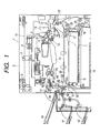
- a copying machine (image forming apparatus) 1 is a both-face copying machine capable of forming images on both surfaces of a single sheet.
- the copying machine 1 includes cassettes 15, 16 in which a plurality of sheets are stacked.
- the sheets having different sizes and stacked in the cassettes 15, 16 are selectively fed to a transfer portion.
- the sheets stacked in the cassettes 15, 16 are sequentially picked up from uppermost ones by pick-up rollers 17, 18 rotated in directions indicated by the arrows.
- the sheets S fed out by the pick-up roller 17 or 18 are separated one by one by a pair of separating rollers 20, 21 rotated in directions indicated by the arrows, and the separated sheet is fed to a second pair of registration rollers 22 and a pair of registration rollers 23 which are now stopped.
- the sheet S of which the skew-feed is corrected is sent to a transfer portion between a photosensitive drum 4 and a transfer charger 12 by the pair of registration rollers 23 which start to be rotated in directions indicated by the arrows at a timing for registering the sheet with a toner image formed on the photosensitive drum 4 rotated in a direction indicated by the arrow.
- the toner image formed on the photosensitive drum 4 is transferred onto the sheet S by the transfer charger 12.
- the photosensitive drum 4, the transfer charger 12 and the developing device 14 constitute image forming means 2 forming an image on the sheet.
- an image on an original (not shown) rested on a platen glass 5 is read by a CCD 10 through an optical system comprising an illumination lamp 6, reflection mirrors 7, 8 and a zoom lens 9, and read data is subjected to predetermined image processing so that a laser beam from a laser scanner is illuminated onto the photosensitive drum 4 rotated in the direction indicated by the arrow.
- An electrostatic latent image formed on the photosensitive drum 4 in this way is visualized by toner supplied from the developing device 14 to form a toner image.
- the sheet S to which the toner image is transferred at the transfer portion is sent, by a conveying belt 13, to a fixing device 24, by which the toner image is fixed onto the sheet.
- the sheet S from the fixing device is sent to a pair of sheet discharge outer rollers 27 by a sheet discharge inner roller 25 and then is discharged by the pair of sheet discharge outer rollers 27 onto a discharge sheet tray 40 out of the machine in a state that the imaged surface of the sheet faces upwardly.
- a flapper 26 disposed at a branched portion has been switched or changed to a position 26a shown by the two dot and dash line in Fig. 2.
- the characteristic of the present invention is a surface reverse method for reversing a front surface and a back surface of the sheet during the conveyance of the face-down discharge sheet onto the three bin trays 40, 41, 42 and during the conveyance of the sheet onto a both-face tray 50.
- Three surface reverse positions are used.
- two pairs of rollers i.e., a pair of first surface reverse rollers 59 and a pair of second surface reverse rollers 60 are provided in a sheet conveying path 80.
- the pairs of rollers are controlled by discrete stepping motors.
- the sheet conveying path 80 is provided with a fixing discharge sheet sensor 62 as a sensor for sheet detection and control.
- the sheet conveying path 80 serves to guide the sheet fed from the image forming means 2 to the pair of second surface reverse rollers 60 through the fixing discharge sheet sensor 62 (described later) and the pair of first surface reverse rollers 59.
- a discharging portion is constituted by a normal discharge path 64, a second discharge path 65 disposed between the pair of first surface reverse rollers 59 and the pair of second surface reverse rollers 60, three bin trays 40, 41, 42 (as discharge ports), and flappers (as rotary members of conveying path changing members)26, 31 for directing the sheet to the discharge paths.
- the flapper (rotary member) 26 When a signal for demanding that the sheet of which size is previously known is discharged onto the tray 40 in a face-down discharge fashion is received, even after the fixing discharge sheet sensor 62 detects the leading end of the sheet, the flapper (rotary member) 26 remains at a position shown by the solid line (26b) and a distal end 29a' of a PET sheet 29a (guide member (guide piece) having elasticity and adhered to a guide piece attaching member 29b provided on the flapper 26) is in pressure contact with an inner wall of the sheet conveying path 80.
- a longitudinal configuration of the guide piece may not be made completely uniform, so long as such a configuration can be urged against the inner wall over the entire length of the guide piece.
- the stepping motors for driving the pair of first surface reverse rollers 59 and the pair of second surface reverse rollers 60 are driven in a forward rotating direction to convey the sheet toward a downstream direction.
- the sheet advances while pushing the distal end 29a' of the PET sheet 29a.
- a predetermined time period Ta is elapsed after the trailing end of the sheet is detected by the fixing discharge sheet sensor 62, the pair of first surface reverse rollers 59 and the pair of second surface reverse rollers 60 are rotated reversely to feed the sheet back toward an upstream direction.
- the flapper 31 is provided with the PET sheet 31a, by the guidance of the PET sheet 31a, the sheet can be conveyed toward a direction indicated by the arrow Q is that the face-down sheet can be discharged onto the tray 41 or 42.
- the flappers (rotary members) 26, 31 and the PET sheets (guide pieces) 29a, 31a provided on the flappers 26, 31 constitute conveying path changing members 32, 33, and the conveying path changing members 32 is rotatably disposed at a branched portion 81 between the sheet conveying path 80 and a first discharge path (sheet surface reverse conveying path) 64, and the conveying path changing member 33 is rotatably disposed at a branched portion 82 between the sheet conveying path 80 and a second discharge path (sheet surface reverse conveying path) 65.
- the PET sheets as guide members (guide pieces) having elasticity which are characteristics of the illustrated embodiment are used in the three surface reverse positions A, B, C.
- a securing method and a using methods at three positions will now be described concretely.
- the PET sheet 29a is disposed to abut against a recessed portion 66b formed in an intermediate area of a curved portion 66a of a guide 66 forming a part of a conveying path between the roller 25 and the pair of rollers 59.
- the curved portion 66a is curved to protrude into the conveying path 80.
- the surface reverse position A is arranged in the vicinity of a terminal portion of the curved portion 66a of the guide 66 which is transition of the sheet convey path 80 from a horizontal path to a vertical path thereof.
- the curved portion 66a and the recessed portion 66b form interference avoiding members, respectively and constitute interference avoiding means.
- the distal end 29a' of the PET sheet 29a is concealed by the curved portion 66a when looking in the direction of the tangential line of the pair of first surface reverse rollers 59 (opposite to the surface reverse conveying path with respect to the tangential line T), so that, during the surface reversing, the leading end of the sheet can be prevented from being caught by the distal end 29a' of the PET sheet 29a.
- the leading end of the sheet can be prevented from being caught by the distal end 29a' of the guide piece 29a more securely.
- the guide piece having the substantially uniform longitudinal configuration can be used, there is no problem of catching the sheet by deformed protruded portions or recessed portions of the pectination shape, which would occur in the conventional guide piece having such pectination shape. Further, since there is no holes through which distal ends of Mylar are protruded as shown in Fig. 12, there is no problem of catching the sheet by the holes.
- a sensor hole 66c for sheet detection is formed in the guide 66, so long as such a hole is disposed not to interfere with the side edges of the sheet and has a dimension to the extent of the size used for the sensor, the effect of the present invention is not worsened.
- the combination of the curved portion 66a and the recessed portion 66b was explained, even when these portions are used independently, adequate effect can be expected.
- the characteristic of the surface reverse position B is that a smooth projection (as interference avoiding member (means) 51b is provided at a point immediately downstream side of an area of guide 51 opposed to the distal end 31a' of the PET sheet (guide member) 31a adhered to the flapper (rotary member) 31 in such a manner that the projection 51b does not impede bidirectional conveyance ability of the sheet.
- the distal end of the PET sheet abuts against the guide 51 upstream of the projection 51b in the sheet conveying direction.
- the distal end 31a' of the PET sheet 31a is concealed with respect to the sheet reverse conveying direction, thereby enhancing the prevention of interference of the curled sheet during the surface reversing operation. Since the guide plate has no hole, the leading end of the sheet is not caught by the guide plate. Further, when a difference X in height between the projection 51b and the distal end 31a' of the PET sheet 31a is increased, the prevention of interference can be ensured more positively (Fig. 6A).
- a recessed portion 51c as a interference avoiding member (means) may be formed in the area of the guide 51 opposed to the distal end 31a' of the PET sheet 31a (Fig. 6C). In this case, since the sheet passes over the distal end 31a' of the PET sheet 31a, the same effect as that in the embodiment shown in Fig. 6A can be achieved.
- a height of the projection 51b is greater than a predetermined value, it is not necessary that the height of the projection is uniform along the longitudinal direction.
- a height at a longitudinal end in which the curl of the sheet is considered to become great is particularly increased.
- the recessed portion 51c for the same reason, so long as a depth of the recessed portion is greater than a predetermined value, it is not necessary that the depth of the recessed portion is uniform along the longitudinal direction.
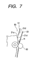
- the PET sheet 51a When the sheet conveyed through the sheet conveying path 80 passes by a branched portion 51d while pushing the distal end 51a' of the PET sheet (reverse feed preventing member having elasticity) 51a, the PET sheet 51a is restored to its original state by its elasticity, thereby closing or blocking the sheet conveying path 80 at the branched portion 51d.
- the pair of second surface reverse rollers (rotary members) 60 are rotated reversely to feed the sheet reversely.
- a common tangential line H of the pair of second surface reverse rollers 60 (tangential line at the nip between these rollers) is oriented toward a sheet surface reverse conveying path 83 to the both-face tray 50, the pair of second surface reverse rollers 60 guide the sheet into the sheet surface reverse conveying path 83 while feeding the sheet reversely.
- the common tangential line H of the pair of second surface reverse rollers 60 is oriented toward the sheet surface reverse conveying path 83, and since the distal end 51a' of the PET sheet 51a is located at a position opposite to the sheet surface reverse conveying path 83 with respect to the common tangential line H, a leading end of the sheet conveyed reversely (trailing end of the sheet when it is conveyed through the sheet conveying path) is prevented from abutting against the distal end 51a'. In this way, the sheet is guided into the sheet surface reverse conveying path 83 in a switch-back fashion, thereby preventing the sheet from being jammed. Further, as is in the illustrated embodiment, by using the reverse feed preventing member 51a, even when the sheet has great curl, the sheet can be guided into the sheet reverse conveying path 83 more securely.
- the sheet surface reversing device by the provision of the interference avoiding means, since the leading end of the sheet fed reversely passes over the rotating distal end of the conveying path changing member to avoid the interference between the leading end of the sheet and the rotating distal end of the conveying path changing member, the sheet fed reversely can be guided into the sheet surface reverse conveying path smoothly. As a result, the sheet jam and sheet damage due to the switching of the conveying path changing member can be prevented. Further, the sheet surface reversing device can be made compact and simplified.
- the rotating distal end of the guide member is closely contacted with the inner wall of the sheet conveying path not to protrude from the interference avoiding means, so that the interference between the leading end of the sheet fed reversely and the distal end of the guide member can surely be avoided. Further, when the longitudinal configuration of the guide member is made substantially uniform, the catching of the sheet can be prevented more securely.
- the image forming apparatus since the image forming apparatus according to the above embodiment has the above-mentioned sheet surface reversing device, the sheet on which the image is formed can surely be discharged out of the main body of the image forming apparatus.
Landscapes
- Physics & Mathematics (AREA)
- General Physics & Mathematics (AREA)
- Separation, Sorting, Adjustment, Or Bending Of Sheets To Be Conveyed (AREA)
Claims (7)
- Blattoberflächenumkehrvorrichtung mit:dadurch gekennzeichnet, dasseiner Blattförderbahn (80), durch die ein Blatt befördert wird;einem Paar an Drehelementen (60) für ein umgekehrtes Zuführen des Blattes, das durch die Blattförderbahn (80) befördert wird,einer Blattoberflächenumkehrförderbahn (83), zu der das Blatt umgekehrt zugeführt wird, wobei die Blattoberflächenumkehrförderbahn (83) von der Blattförderbahn (80) abzweigt, undeinem elastischen Umkehrzuführverhinderungselement (51a), das bei einem Abzweigungsabschnitt zwischen der Blattförderbahn (80) und der Blattoberflächenumkehrförderbahn (83) vorgesehen ist undeinen im wesentlichen gleichförmigen Längsaufbau hat, um so zu verhindern, dass das Blatt von der Blattförderbahn (80) zu dem Paar an Drehelementen (60) befördert wird, und zu ermöglichen, dass das Blatt in die Blattoberflächenumkehrförderbahn (83) eintritt, während verhindert wird, dass das Blatt von dem Paar an Drehelementen (60) in die Blattförderbahn (80) eintritt,
das Paar an Drehelementen (60) so angeordnet ist, dass eine tangentiale Linie von einem Spalt von dem Paar an Drehelementen (60) zu einer Wand der Blattoberflächenumkehrförderbahn ausgerichtet ist, die einem distalen Ende (51a') von dem elastischen Umkehrzuführverhinderungselement (51a) gegenübersteht. - Blattoberflächenumkehrvorrichtung gemäß Anspruch 1, die des weiteren eine Beeinträchtigungsverhinderungseinrichtung aufweist, die eine Beeinträchtigung zwischen dem Blatt, das umgekehrt zugeführt wird, und einem Förderbahnänderungselement (31), das drehbar an dem Abzweigungsabschnitt angeordnet ist, verhindert,
dadurch gekennzeichnet, dass
die Beeinträchtigungsverhinderungseinrichtung einen gekrümmten Abschnitt (66a) aufweist, der in die Blattförderbahn (80) von einer Innenwand der Blattförderbahn hineinragt, und wobei das distale Ende von dem Förderbahnänderungselement an einem Zwischenabschnitt des gekrümmten Abschnittes (66a) anliegt. - Blattoberflächenumkehrvorrichtung gemäß Anspruch 1, die des weiteren eine Beeinträchtigungsverhinderungseinrichtung aufweist, um eine Beeinträchtigung zwischen dem Blatt, das umgekehrt zugeführt wird, und einem Förderbahnänderungselement (31), das drehbar an dem Abzweigungsabschnitt angeordnet ist, zu verhindern,
dadurch gekennzeichnet, dass
die Beeinträchtigungsverhinderungseinrichtung einen Vorsprung (51b) aufweist, der in die Blattförderbahn (80) von einer Innenwand der Blattförderbahn hineinragt, und das distale Ende von dem Förderbahnänderungselement an einem Bereich stromaufwärtig von dem Vorsprung (51b) in der Blattförderbahn (80) anliegt. - Blattoberflächenumkehrvorrichtung gemäß Anspruch 1, die des weiteren eine Beeinträchtigungsverhinderungseinrichtung aufweist, die eine Beeinträchtigung zwischen dem Blatt, das umgekehrt zugeführt wird, und einem Förderbahnänderungselement (31), das an dem Abzweigungsabschnitt drehbar angeordnet ist, verhindert,
dadurch gekennzeichnet, dass
die Beeinträchtigungsverhinderungseinrichtung einen Vertiefungsabschnitt (51c, 66b) aufweist, der an einer Innenwand von der Blattförderbahn (80) ausgebildet ist, und das distale Ende von dem Förderbahnänderungselement an dem Vertiefungsabschnitt (51c, 66b) anliegt. - Blattoberflächenumkehrvorrichtung gemäß Anspruch 1, die des weiteren eine Beeinträchtigungsverhinderungseinrichtung aufweist, die eine Beeinträchtigung zwischen dem Blatt, das umgekehrt zugeführt wird, und einem Förderbahnänderungselement (31), das an dem Abzweigungsabschnitt drehbar angeordnet ist, verhindert,
dadurch gekennzeichnet, dass
die Beeinträchtigungsverhinderungseinrichtung einen gekrümmten Abschnitt (66a), der in die Blattförderbahn (80) vorragt, und einen Vorsprung (51a) aufweist, der von dem Förderbahnänderungselement (31), das an dem Abzweigungsabschnitt drehbar angeordnet ist, an dem gekrümmten Abschnitt (66a) vorragt, und wobei das distale Ende von dem Förderbahnänderungselement an einem Bereich stromaufwärtig von dem Vorsprung (51b) in der Blattförderbahn (80) anlegt. - Blattoberflächenumkehrvorrichtung gemäß Anspruch 1, die des weiteren eine Beeinträchtigungsverhinderungseinrichtung aufweist, die eine Beeinträchtigung zwischen dem Blatt, das umgekehrt zugeführt wird, und einem Förderbahnänderungselement (31), das drehbar an dem Abzweigungsabschnitt angeordnet ist, verhindert,
dadurch gekennzeichnet, dass
die Beeinträchtigungsverhinderungseinrichtung einen gekrümmten Abschnitt (66a) von einer Innenwand der Blattförderbahn, der in die Blattförderbahn (88) vorragt, und einen Vertiefungsabschnitt (51c, 66b) aufweist, der an der Innenwand in dem gekrümmten Abschnitt (66a) ausgebildet ist, und wobei das distale Ende von dem Förderbahnänderungselement an dem Vertiefungsabschnitt (51c, 66b) anliegt. - Bilderzeugungsgerät (1) mit
einer Bilderzeugniseinrichtung (2) für ein Erzeugen eines Bildes auf einem Blatt und
einer Blattoberflächenumkehrvorrichtung für ein Umkehren der Oberflächen des Blattes, an dem das Bild durch die Bilderzeugungseinrichtung (2) erzeugt wird, und zum Befördern des Blattes,
dadurch gekennzeichnet, dass
die Blattoberflächenumkehrvorrichtung eine Blattoberflächenumkehrungsvorrichtung gemäß einem der Ansprüche (1-6) ist.
Applications Claiming Priority (2)
| Application Number | Priority Date | Filing Date | Title |
|---|---|---|---|
| JP36150898 | 1998-12-18 | ||
| JP36150898 | 1998-12-18 |
Publications (3)
| Publication Number | Publication Date |
|---|---|
| EP1014223A2 EP1014223A2 (de) | 2000-06-28 |
| EP1014223A3 EP1014223A3 (de) | 2002-01-16 |
| EP1014223B1 true EP1014223B1 (de) | 2005-10-26 |
Family
ID=18473873
Family Applications (1)
| Application Number | Title | Priority Date | Filing Date |
|---|---|---|---|
| EP99125097A Expired - Lifetime EP1014223B1 (de) | 1998-12-18 | 1999-12-16 | Blattoberflächenwendevorrichtung und Bilderzeugungsgerät mit einem solchen |
Country Status (3)
| Country | Link |
|---|---|
| US (1) | US6398212B1 (de) |
| EP (1) | EP1014223B1 (de) |
| DE (1) | DE69927923T2 (de) |
Families Citing this family (14)
| Publication number | Priority date | Publication date | Assignee | Title |
|---|---|---|---|---|
| JP2003128350A (ja) * | 2001-10-30 | 2003-05-08 | Canon Inc | シート搬送装置及び画像形成装置 |
| JP2003141639A (ja) * | 2001-11-05 | 2003-05-16 | Nec Infrontia Corp | レシート発券方法およびレシートプリンタ |
| US6565274B1 (en) * | 2001-12-31 | 2003-05-20 | Ncr Corporation | Sheet printing and discharging apparatus |
| JP2003212382A (ja) * | 2002-01-23 | 2003-07-30 | Konica Corp | 原稿搬送装置及び画像形成装置 |
| JP3805269B2 (ja) * | 2002-03-13 | 2006-08-02 | キヤノン株式会社 | シート案内装置及び該装置を備えた画像形成装置 |
| US6669190B1 (en) * | 2002-07-12 | 2003-12-30 | Lite-On Technology Corporation | Double-side automatic feeding apparatus |
| US6981636B2 (en) * | 2002-12-19 | 2006-01-03 | Ncr Corporation | Document path selector apparatus for use in a self-service terminal |
| US7216866B2 (en) * | 2003-04-28 | 2007-05-15 | Kyocera Mita Corporation | Sheet transport path switching mechanism |
| JP4217566B2 (ja) * | 2003-09-01 | 2009-02-04 | キヤノン株式会社 | シート処理装置および画像形成装置 |
| JP4908894B2 (ja) * | 2006-03-30 | 2012-04-04 | キヤノン株式会社 | 画像形成装置 |
| JP5172257B2 (ja) * | 2007-09-12 | 2013-03-27 | グローリー株式会社 | 紙葉類分岐機構、紙葉類処理装置および紙葉類分岐方法 |
| JP5521637B2 (ja) * | 2010-02-25 | 2014-06-18 | 株式会社リコー | シート搬送装置及び画像形成装置 |
| EP3023375A1 (de) * | 2014-11-21 | 2016-05-25 | OCE-Technologies B.V. | Folienablenkeinheit |
| TWI622961B (zh) | 2017-06-27 | 2018-05-01 | 鴻發國際科技股份有限公司 | 輸送路徑切換模組、紙頁處理模組及紙頁處理設備 |
Family Cites Families (12)
| Publication number | Priority date | Publication date | Assignee | Title |
|---|---|---|---|---|
| US4234305A (en) | 1977-11-24 | 1980-11-18 | Canon Kabushiki Kaisha | Transfer sheet guiding device |
| JPS59118482A (ja) | 1982-11-20 | 1984-07-09 | Brother Ind Ltd | 印字装置のための用紙給送装置 |
| JPS63295357A (ja) | 1987-05-27 | 1988-12-01 | Canon Inc | シ−ト反転装置 |
| US4958828A (en) * | 1988-05-01 | 1990-09-25 | Minolta Camera Kabushiki Kaisha | Sheets handling device |
| JPH04119866A (ja) * | 1990-09-10 | 1992-04-21 | Minolta Camera Co Ltd | 画像作成装置 |
| JP2890916B2 (ja) | 1991-08-21 | 1999-05-17 | ミノルタ株式会社 | 用紙反転装置 |
| JPH05323730A (ja) | 1992-05-15 | 1993-12-07 | Fuji Xerox Co Ltd | 用紙搬送方向切換え装置 |
| JPH0638838A (ja) | 1992-07-22 | 1994-02-15 | Tsutomu Abe | 業務支援型システムキヤビネツト |
| JPH0881105A (ja) | 1994-09-13 | 1996-03-26 | Ricoh Co Ltd | 用紙反転装置 |
| JP3131122B2 (ja) | 1995-05-22 | 2001-01-31 | キヤノン株式会社 | シート給送装置および画像形成装置 |
| DE59703823D1 (de) * | 1996-10-22 | 2001-07-19 | Oce Printing Systems Gmbh | Wendeanordnung für blattförmiges material |
| US6186496B1 (en) * | 1998-08-31 | 2001-02-13 | Xerox Corporation | Optimized passive gate inverter |
-
1999
- 1999-12-15 US US09/461,762 patent/US6398212B1/en not_active Expired - Lifetime
- 1999-12-16 DE DE69927923T patent/DE69927923T2/de not_active Expired - Lifetime
- 1999-12-16 EP EP99125097A patent/EP1014223B1/de not_active Expired - Lifetime
Also Published As
| Publication number | Publication date |
|---|---|
| DE69927923D1 (de) | 2005-12-01 |
| EP1014223A2 (de) | 2000-06-28 |
| DE69927923T2 (de) | 2006-07-20 |
| US6398212B1 (en) | 2002-06-04 |
| EP1014223A3 (de) | 2002-01-16 |
Similar Documents
| Publication | Publication Date | Title |
|---|---|---|
| US6209861B1 (en) | Sheet transport device and automatic document feeder | |
| EP1014223B1 (de) | Blattoberflächenwendevorrichtung und Bilderzeugungsgerät mit einem solchen | |
| US6161831A (en) | Sheet transport device and automatic document feeder | |
| US20030122299A1 (en) | Sheet ejection mechanism | |
| US6402133B1 (en) | Sheet conveying apparatus and image forming apparatus having the same | |
| JP2010143696A (ja) | 画像形成装置 | |
| US6333797B1 (en) | Document feeder and method of document reading | |
| EP1055623B1 (de) | Bogenzuführer mit Mittel zum seitlichen Justieren | |
| JP3445966B2 (ja) | 自動両面装置、およびこの自動両面装置を備えた画像形成装置 | |
| JP3855567B2 (ja) | 画像形成装置およびその付加給紙装置 | |
| JP3740768B2 (ja) | 自動原稿搬送装置 | |
| JP3754854B2 (ja) | シート反転装置とこの装置を備えた画像形成装置 | |
| JP2001226016A (ja) | 画像形成装置 | |
| JP4022064B2 (ja) | 用紙搬送装置及び画像形成装置 | |
| JP3495600B2 (ja) | 用紙の斜め搬送補正装置 | |
| JPH10186738A (ja) | 画像形成装置 | |
| JP2002187666A (ja) | シート整合装置とこの装置を備えたシート後処理装置および画像形成装置 | |
| JP3450610B2 (ja) | シート反転搬送装置及びシート処理装置 | |
| JP7446839B2 (ja) | シート給送装置、シート給送装置を備えたシート読取装置、シート読取装置を備えた画像形成装置 | |
| JP3935313B2 (ja) | シート搬送装置及びそれを装着した画像形成装置 | |
| JP2941360B2 (ja) | 給紙装置 | |
| JP3086394B2 (ja) | 複写機 | |
| JP2001097622A (ja) | 画像形成装置 | |
| JP2001080806A (ja) | シート搬送装置とこの装置を備えた画像形成装置 | |
| JP2003182906A (ja) | 用紙反転装置及びそれを備えた画像形成装置 |
Legal Events
| Date | Code | Title | Description |
|---|---|---|---|
| PUAI | Public reference made under article 153(3) epc to a published international application that has entered the european phase |
Free format text: ORIGINAL CODE: 0009012 |
|
| AK | Designated contracting states |
Kind code of ref document: A2 Designated state(s): AT BE CH CY DE DK ES FI FR GB GR IE IT LI LU MC NL PT SE Kind code of ref document: A2 Designated state(s): DE FR GB IT |
|
| AX | Request for extension of the european patent |
Free format text: AL;LT;LV;MK;RO;SI |
|
| PUAL | Search report despatched |
Free format text: ORIGINAL CODE: 0009013 |
|
| AK | Designated contracting states |
Kind code of ref document: A3 Designated state(s): AT BE CH CY DE DK ES FI FR GB GR IE IT LI LU MC NL PT SE |
|
| AX | Request for extension of the european patent |
Free format text: AL;LT;LV;MK;RO;SI |
|
| 17P | Request for examination filed |
Effective date: 20020529 |
|
| 17Q | First examination report despatched |
Effective date: 20020816 |
|
| AKX | Designation fees paid |
Free format text: DE FR GB IT |
|
| GRAP | Despatch of communication of intention to grant a patent |
Free format text: ORIGINAL CODE: EPIDOSNIGR1 |
|
| GRAS | Grant fee paid |
Free format text: ORIGINAL CODE: EPIDOSNIGR3 |
|
| GRAA | (expected) grant |
Free format text: ORIGINAL CODE: 0009210 |
|
| AK | Designated contracting states |
Kind code of ref document: B1 Designated state(s): DE FR GB IT |
|
| PG25 | Lapsed in a contracting state [announced via postgrant information from national office to epo] |
Ref country code: IT Free format text: LAPSE BECAUSE OF FAILURE TO SUBMIT A TRANSLATION OF THE DESCRIPTION OR TO PAY THE FEE WITHIN THE PRE;WARNING: LAPSES OF ITALIAN PATENTS WITH EFFECTIVE DATE BEFORE 2007 MAY HAVE OCCURRED AT ANY TIME BEFORE 2007. THE CORRECT EFFECTIVE DATE MAY BE DIFFERENT FROM THE ONE RECORDED.SCRIBED TIME-LIMIT Effective date: 20051026 |
|
| REG | Reference to a national code |
Ref country code: GB Ref legal event code: FG4D |
|
| REF | Corresponds to: |
Ref document number: 69927923 Country of ref document: DE Date of ref document: 20051201 Kind code of ref document: P |
|
| PG25 | Lapsed in a contracting state [announced via postgrant information from national office to epo] |
Ref country code: GB Free format text: LAPSE BECAUSE OF NON-PAYMENT OF DUE FEES Effective date: 20060126 |
|
| PLBE | No opposition filed within time limit |
Free format text: ORIGINAL CODE: 0009261 |
|
| STAA | Information on the status of an ep patent application or granted ep patent |
Free format text: STATUS: NO OPPOSITION FILED WITHIN TIME LIMIT |
|
| GBPC | Gb: european patent ceased through non-payment of renewal fee |
Effective date: 20060126 |
|
| 26N | No opposition filed |
Effective date: 20060727 |
|
| EN | Fr: translation not filed | ||
| PG25 | Lapsed in a contracting state [announced via postgrant information from national office to epo] |
Ref country code: FR Free format text: LAPSE BECAUSE OF FAILURE TO SUBMIT A TRANSLATION OF THE DESCRIPTION OR TO PAY THE FEE WITHIN THE PRESCRIBED TIME-LIMIT Effective date: 20061215 |
|
| PG25 | Lapsed in a contracting state [announced via postgrant information from national office to epo] |
Ref country code: FR Free format text: LAPSE BECAUSE OF FAILURE TO SUBMIT A TRANSLATION OF THE DESCRIPTION OR TO PAY THE FEE WITHIN THE PRESCRIBED TIME-LIMIT Effective date: 20051231 |
|
| PG25 | Lapsed in a contracting state [announced via postgrant information from national office to epo] |
Ref country code: FR Free format text: LAPSE BECAUSE OF FAILURE TO SUBMIT A TRANSLATION OF THE DESCRIPTION OR TO PAY THE FEE WITHIN THE PRESCRIBED TIME-LIMIT Effective date: 20051026 |
|
| PGFP | Annual fee paid to national office [announced via postgrant information from national office to epo] |
Ref country code: DE Payment date: 20151231 Year of fee payment: 17 |
|
| REG | Reference to a national code |
Ref country code: DE Ref legal event code: R119 Ref document number: 69927923 Country of ref document: DE |
|
| PG25 | Lapsed in a contracting state [announced via postgrant information from national office to epo] |
Ref country code: DE Free format text: LAPSE BECAUSE OF NON-PAYMENT OF DUE FEES Effective date: 20170701 |