EP1014245A1 - Robinet pour bouteille avec des moyens de réduction de pression - Google Patents
Robinet pour bouteille avec des moyens de réduction de pression Download PDFInfo
- Publication number
- EP1014245A1 EP1014245A1 EP99125258A EP99125258A EP1014245A1 EP 1014245 A1 EP1014245 A1 EP 1014245A1 EP 99125258 A EP99125258 A EP 99125258A EP 99125258 A EP99125258 A EP 99125258A EP 1014245 A1 EP1014245 A1 EP 1014245A1
- Authority
- EP
- European Patent Office
- Prior art keywords
- bottle
- closure device
- pressure
- gas
- bottle closure
- Prior art date
- Legal status (The legal status is an assumption and is not a legal conclusion. Google has not performed a legal analysis and makes no representation as to the accuracy of the status listed.)
- Withdrawn
Links
- 239000003638 chemical reducing agent Substances 0.000 description 6
- 230000001681 protective effect Effects 0.000 description 3
- 230000001105 regulatory effect Effects 0.000 description 3
- 238000000605 extraction Methods 0.000 description 2
- 230000036316 preload Effects 0.000 description 2
- 241001411320 Eriogonum inflatum Species 0.000 description 1
- 230000003247 decreasing effect Effects 0.000 description 1
- 230000001419 dependent effect Effects 0.000 description 1
- 238000005070 sampling Methods 0.000 description 1
- 238000007789 sealing Methods 0.000 description 1
Images
Classifications
-
- F—MECHANICAL ENGINEERING; LIGHTING; HEATING; WEAPONS; BLASTING
- F17—STORING OR DISTRIBUTING GASES OR LIQUIDS
- F17C—VESSELS FOR CONTAINING OR STORING COMPRESSED, LIQUEFIED OR SOLIDIFIED GASES; FIXED-CAPACITY GAS-HOLDERS; FILLING VESSELS WITH, OR DISCHARGING FROM VESSELS, COMPRESSED, LIQUEFIED, OR SOLIDIFIED GASES
- F17C13/00—Details of vessels or of the filling or discharging of vessels
- F17C13/04—Arrangement or mounting of valves
-
- G—PHYSICS
- G05—CONTROLLING; REGULATING
- G05D—SYSTEMS FOR CONTROLLING OR REGULATING NON-ELECTRIC VARIABLES
- G05D16/00—Control of fluid pressure
- G05D16/04—Control of fluid pressure without auxiliary power
- G05D16/0402—Control of fluid pressure without auxiliary power with two or more controllers mounted in series
-
- G—PHYSICS
- G05—CONTROLLING; REGULATING
- G05D—SYSTEMS FOR CONTROLLING OR REGULATING NON-ELECTRIC VARIABLES
- G05D16/00—Control of fluid pressure
- G05D16/04—Control of fluid pressure without auxiliary power
- G05D16/06—Control of fluid pressure without auxiliary power the sensing element being a flexible membrane, yielding to pressure, e.g. diaphragm, bellows, capsule
- G05D16/063—Control of fluid pressure without auxiliary power the sensing element being a flexible membrane, yielding to pressure, e.g. diaphragm, bellows, capsule the sensing element being a membrane
- G05D16/0644—Control of fluid pressure without auxiliary power the sensing element being a flexible membrane, yielding to pressure, e.g. diaphragm, bellows, capsule the sensing element being a membrane the membrane acting directly on the obturator
- G05D16/0672—Control of fluid pressure without auxiliary power the sensing element being a flexible membrane, yielding to pressure, e.g. diaphragm, bellows, capsule the sensing element being a membrane the membrane acting directly on the obturator using several spring-loaded membranes
-
- F—MECHANICAL ENGINEERING; LIGHTING; HEATING; WEAPONS; BLASTING
- F17—STORING OR DISTRIBUTING GASES OR LIQUIDS
- F17C—VESSELS FOR CONTAINING OR STORING COMPRESSED, LIQUEFIED OR SOLIDIFIED GASES; FIXED-CAPACITY GAS-HOLDERS; FILLING VESSELS WITH, OR DISCHARGING FROM VESSELS, COMPRESSED, LIQUEFIED, OR SOLIDIFIED GASES
- F17C2201/00—Vessel construction, in particular geometry, arrangement or size
- F17C2201/01—Shape
- F17C2201/0104—Shape cylindrical
- F17C2201/0109—Shape cylindrical with exteriorly curved end-piece
-
- F—MECHANICAL ENGINEERING; LIGHTING; HEATING; WEAPONS; BLASTING
- F17—STORING OR DISTRIBUTING GASES OR LIQUIDS
- F17C—VESSELS FOR CONTAINING OR STORING COMPRESSED, LIQUEFIED OR SOLIDIFIED GASES; FIXED-CAPACITY GAS-HOLDERS; FILLING VESSELS WITH, OR DISCHARGING FROM VESSELS, COMPRESSED, LIQUEFIED, OR SOLIDIFIED GASES
- F17C2205/00—Vessel construction, in particular mounting arrangements, attachments or identifications means
- F17C2205/01—Mounting arrangements
- F17C2205/0153—Details of mounting arrangements
- F17C2205/018—Supporting feet
-
- F—MECHANICAL ENGINEERING; LIGHTING; HEATING; WEAPONS; BLASTING
- F17—STORING OR DISTRIBUTING GASES OR LIQUIDS
- F17C—VESSELS FOR CONTAINING OR STORING COMPRESSED, LIQUEFIED OR SOLIDIFIED GASES; FIXED-CAPACITY GAS-HOLDERS; FILLING VESSELS WITH, OR DISCHARGING FROM VESSELS, COMPRESSED, LIQUEFIED, OR SOLIDIFIED GASES
- F17C2205/00—Vessel construction, in particular mounting arrangements, attachments or identifications means
- F17C2205/03—Fluid connections, filters, valves, closure means or other attachments
- F17C2205/0302—Fittings, valves, filters, or components in connection with the gas storage device
- F17C2205/0308—Protective caps
-
- F—MECHANICAL ENGINEERING; LIGHTING; HEATING; WEAPONS; BLASTING
- F17—STORING OR DISTRIBUTING GASES OR LIQUIDS
- F17C—VESSELS FOR CONTAINING OR STORING COMPRESSED, LIQUEFIED OR SOLIDIFIED GASES; FIXED-CAPACITY GAS-HOLDERS; FILLING VESSELS WITH, OR DISCHARGING FROM VESSELS, COMPRESSED, LIQUEFIED, OR SOLIDIFIED GASES
- F17C2205/00—Vessel construction, in particular mounting arrangements, attachments or identifications means
- F17C2205/03—Fluid connections, filters, valves, closure means or other attachments
- F17C2205/0302—Fittings, valves, filters, or components in connection with the gas storage device
- F17C2205/0323—Valves
- F17C2205/0332—Safety valves or pressure relief valves
-
- F—MECHANICAL ENGINEERING; LIGHTING; HEATING; WEAPONS; BLASTING
- F17—STORING OR DISTRIBUTING GASES OR LIQUIDS
- F17C—VESSELS FOR CONTAINING OR STORING COMPRESSED, LIQUEFIED OR SOLIDIFIED GASES; FIXED-CAPACITY GAS-HOLDERS; FILLING VESSELS WITH, OR DISCHARGING FROM VESSELS, COMPRESSED, LIQUEFIED, OR SOLIDIFIED GASES
- F17C2205/00—Vessel construction, in particular mounting arrangements, attachments or identifications means
- F17C2205/03—Fluid connections, filters, valves, closure means or other attachments
- F17C2205/0302—Fittings, valves, filters, or components in connection with the gas storage device
- F17C2205/0382—Constructional details of valves, regulators
-
- F—MECHANICAL ENGINEERING; LIGHTING; HEATING; WEAPONS; BLASTING
- F17—STORING OR DISTRIBUTING GASES OR LIQUIDS
- F17C—VESSELS FOR CONTAINING OR STORING COMPRESSED, LIQUEFIED OR SOLIDIFIED GASES; FIXED-CAPACITY GAS-HOLDERS; FILLING VESSELS WITH, OR DISCHARGING FROM VESSELS, COMPRESSED, LIQUEFIED, OR SOLIDIFIED GASES
- F17C2205/00—Vessel construction, in particular mounting arrangements, attachments or identifications means
- F17C2205/03—Fluid connections, filters, valves, closure means or other attachments
- F17C2205/0302—Fittings, valves, filters, or components in connection with the gas storage device
- F17C2205/0382—Constructional details of valves, regulators
- F17C2205/0385—Constructional details of valves, regulators in blocks or units
Definitions
- the invention relates to a bottle closure device for a compressed gas bottle a closing element and an actuating element for actuating the Closing element, the closing element in an opening of the gas bottle closing and opening the opening of the gas bottle position can be brought.
- the object of the present invention is therefore to provide a bottle closure device develop that avoids the disadvantages mentioned above.
- Bottle closure device a device for reducing pressure is integrated, which can be activated by means of the actuating element.
- a second is preferably attached to the bottle closure device according to the invention Pressure reducer connected.
- the entire gas bottle fitting thus receives one two-stage pressure reduction. First the gas bottle pressure is compared to that in the Bottle closure device integrated device for reducing pressure, then with the second pressure reducer on the one on the Gas withdrawal connection connected consumer demanded consumption pressure decreased.
- the consumption pressure can thus be regulated more precisely and is from instantaneous bottle pressure essentially independent.
- the closing element in the opening of the gas bottle is advantageous locking position held by a force that is independent of that on the Actuator attacking force is. I.e. the closing element closes the Gas bottle always just as tight, regardless of the force with which a user for example, turns the valve wheel of the bottle closure device. Thereby damage to the locking element or seals avoided, which can otherwise occur if the user tries by force to close the bottle. On the other hand, it ensures that even with little An absolutely secure closure of the bottle is achieved because the Locking function regardless of the force acting on the actuating element is.
- the actuating element has exactly two setting positions.
- the actuating element Closing element either in the "open” position or in the "closed” position brought.
- the closing element opens the opening of the gas bottle, the in of the gas bottle prevailing by means of the in the Bottle closure device integrated pressure reducer automatically reduced.
- the degree of pressure reduction is adjustable by means of the actuating element.
- the actuation angle of the actuation button of the bottle closure device is advantageously not more than 270 °, preferably not more than 180 °, particularly preferably not more than 150 °.
- the small actuation angle enables a quick Opening and closing the bottle stopper. This will both Ease of use and the security of the overall system are increased. In case of danger the bottle can be closed with a quick movement.
- the actuating button of the bottle closure device snaps into its End positions “bottle open” and “bottle closed”.
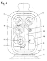
- Figure 1 is a gas bottle fitting with the invention Bottle closure device shown schematically in the front view.
- the on The fittings attached to the head of the gas bottle 1 are protected by a protective cap 2 protected against damage.
- the protective cap 2 has an access window 3, through which without removing the protective cap 2 all for the consumer relevant control and display elements of the valve are accessible and visible.
- the fitting screwed onto the gas bottle 1 consists, among other things, of a Bottle closure device 11 with integrated pressure reducer and one Actuator 5, a knob 6 for a second pressure reducer, one Manometer 7 for the pressure in the gas bottle 1 and a manometer 8 for the the gas extraction connection 9 pending consumption pressure.
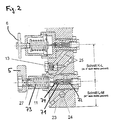
- FIG. 2 shows a section along the line K-L-M in Figure 1.
- the valve body 23 is screwed gas-tight into the bottle 1.
- a central bore runs through the valve body 23 along the bottle axis 24, with which the bottle closure device 11 and the manometer 7 in connection stand.
- the bore 24 is in its upper area by a safety valve completed, which an undesirable escape of gas from the bottle 1 prevented.
- the bottle closure device 11 has an actuating element 5 with which one axially movable spindle 27 is connected in a steep thread.
- the spindle 27 is in operative connection with a closing element 71.
- the closing element 71 is biased by springs 72 and 73.
- the actuating element 5 is designed as a lever. By turning the lever 5 around at an angle 12 of 180 °, the closing element 71 is from the open to the brought closed position. In the latter position, the closing element 71 pressed against the sealing surface to the channel 74 due to the spring force 72. A Damage to the closing element 71 by violent actuation of the lever 5 locked out. Should the bottle closure device 11 tear off, the spring 72, the closing element 71 is automatically in the brought closed position.
- the closing element 71 is affected by the pressure of the channel 24 high-pressure gas flowing in from the gas bottle and the spring force of two springs 72, 73 acted upon.
- the spring preloads are set so that the gas pressure in the bottle is reduced from 200 or 300 bar to about 30 bar.
- the entire system thus receives a two-stage pressure control, which means that Consumption pressure can be regulated more precisely.
- the influence of the current Bottle pressure on the regulated consumption pressure is essentially switched off.
- the bottle closure device 11 can also be used variable pressure reducing function can be performed.
- variable pressure reducing function can be performed.
- the spring preload 73 can be varied and the pressure of the through the gas flowing through the channel 74 released by the closing element 71 and thus the pressure of the gas supplied to the consumer can be adjusted.
Landscapes
- Physics & Mathematics (AREA)
- Engineering & Computer Science (AREA)
- Fluid Mechanics (AREA)
- General Physics & Mathematics (AREA)
- Automation & Control Theory (AREA)
- Mechanical Engineering (AREA)
- General Engineering & Computer Science (AREA)
- Filling Or Discharging Of Gas Storage Vessels (AREA)
Priority Applications (1)
| Application Number | Priority Date | Filing Date | Title |
|---|---|---|---|
| EP99125258A EP1014245A1 (fr) | 1998-12-18 | 1999-12-17 | Robinet pour bouteille avec des moyens de réduction de pression |
Applications Claiming Priority (7)
| Application Number | Priority Date | Filing Date | Title |
|---|---|---|---|
| DE19858746 | 1998-12-18 | ||
| DE19858746 | 1998-12-18 | ||
| EP99106956 | 1999-04-08 | ||
| DE19915860 | 1999-04-08 | ||
| DE19915860A DE19915860A1 (de) | 1998-12-18 | 1999-04-08 | Flaschenventil mit Druckminderfunktion |
| EP99106956 | 1999-04-08 | ||
| EP99125258A EP1014245A1 (fr) | 1998-12-18 | 1999-12-17 | Robinet pour bouteille avec des moyens de réduction de pression |
Publications (1)
| Publication Number | Publication Date |
|---|---|
| EP1014245A1 true EP1014245A1 (fr) | 2000-06-28 |
Family
ID=27438904
Family Applications (1)
| Application Number | Title | Priority Date | Filing Date |
|---|---|---|---|
| EP99125258A Withdrawn EP1014245A1 (fr) | 1998-12-18 | 1999-12-17 | Robinet pour bouteille avec des moyens de réduction de pression |
Country Status (1)
| Country | Link |
|---|---|
| EP (1) | EP1014245A1 (fr) |
Citations (5)
| Publication number | Priority date | Publication date | Assignee | Title |
|---|---|---|---|---|
| EP0308875A2 (fr) * | 1987-09-21 | 1989-03-29 | Praxair Technology, Inc. | Vanne régulatrice haute pression |
| EP0428901A1 (fr) * | 1989-11-21 | 1991-05-29 | Luxembourg Patent Company S.A. | Détendeur neutralisable |
| US5123409A (en) * | 1990-06-05 | 1992-06-23 | Scott Specialty Gases, Inc. | Emergency oxygen supply system |
| EP0581718A1 (fr) * | 1992-04-14 | 1994-02-02 | Repsol-Butano, S.A. | Régulateur d'étranglement perfectionné pour bouteilles à gas liquifié |
| EP0845729A2 (fr) * | 1993-06-03 | 1998-06-03 | Taema | Ensemble de commande de distrubution de gaz et bouteille de gaz équipée d'un tel ensemble |
-
1999
- 1999-12-17 EP EP99125258A patent/EP1014245A1/fr not_active Withdrawn
Patent Citations (5)
| Publication number | Priority date | Publication date | Assignee | Title |
|---|---|---|---|---|
| EP0308875A2 (fr) * | 1987-09-21 | 1989-03-29 | Praxair Technology, Inc. | Vanne régulatrice haute pression |
| EP0428901A1 (fr) * | 1989-11-21 | 1991-05-29 | Luxembourg Patent Company S.A. | Détendeur neutralisable |
| US5123409A (en) * | 1990-06-05 | 1992-06-23 | Scott Specialty Gases, Inc. | Emergency oxygen supply system |
| EP0581718A1 (fr) * | 1992-04-14 | 1994-02-02 | Repsol-Butano, S.A. | Régulateur d'étranglement perfectionné pour bouteilles à gas liquifié |
| EP0845729A2 (fr) * | 1993-06-03 | 1998-06-03 | Taema | Ensemble de commande de distrubution de gaz et bouteille de gaz équipée d'un tel ensemble |
Similar Documents
| Publication | Publication Date | Title |
|---|---|---|
| EP1447286B1 (fr) | Dispositif de verrouillage pour la colonne de direction d'un vehicule | |
| EP0296618B1 (fr) | Réservoir d'essence autoserrant | |
| DE60302474T2 (de) | Ventil für Druckbehälter | |
| DE102010063291B4 (de) | Sicherheitsverschluss für einen Behälter, dessen Öffnung mit einem Deckel verschließbar ist | |
| EP0071803B1 (fr) | Serrure de direction pour véhicule | |
| DE19915860A1 (de) | Flaschenventil mit Druckminderfunktion | |
| EP1440448A1 (fr) | Dispositif de porte pour isolateur | |
| EP1014245A1 (fr) | Robinet pour bouteille avec des moyens de réduction de pression | |
| EP1254040B1 (fr) | Dispositif de securite | |
| EP3580413A1 (fr) | Serrure de portière de véhicule à moteur | |
| WO2005111478A1 (fr) | Dispositif d'accouplement d'une bouteille de gaz sous pression | |
| DE19911246B4 (de) | Feuerschutz-Absperrvorrichtung | |
| DE102010023574A1 (de) | Eckventil | |
| DE9306539U1 (de) | Feststellvorrichtung für eine mit einem Türschließer versehene Tür | |
| EP1187681B1 (fr) | Buse a air comprime | |
| EP1013986B1 (fr) | Robinetterie de bouteille à gaz | |
| DE2300426A1 (de) | Druckregelventil | |
| DE4022147C2 (de) | Narkosemittelverdunster mit einem Belastungsindikator für die Dosiervorrichtung | |
| DE3102261A1 (de) | "absperrventileinrichtung fuer handfeuerloescher oder sonstige druckgasbehaelter od.dgl." | |
| DE10159510A1 (de) | Vereinfachte Sicherungseinrichtung für Gasanwendungsanlagen | |
| DE10045120B4 (de) | Flaschenverschlussvorrichtung | |
| DE9107640U1 (de) | Rasiermesser bzw. Effiliermesser | |
| EP4194099A1 (fr) | Porte-capsule destiné au logement d'une capsule à gaz | |
| DE20210089U1 (de) | Ventil für einen auf einer Felge sitzenden schlauchlosen Reifen | |
| DE20122621U1 (de) | Tür-Vorrichtung für einen Isolator |
Legal Events
| Date | Code | Title | Description |
|---|---|---|---|
| PUAI | Public reference made under article 153(3) epc to a published international application that has entered the european phase |
Free format text: ORIGINAL CODE: 0009012 |
|
| AK | Designated contracting states |
Kind code of ref document: A1 Designated state(s): AT BE CH CY DE DK ES FI FR GB GR IE IT LI LU MC NL PT SE |
|
| AX | Request for extension of the european patent |
Free format text: AL;LT;LV;MK;RO;SI |
|
| AKX | Designation fees paid | ||
| STAA | Information on the status of an ep patent application or granted ep patent |
Free format text: STATUS: THE APPLICATION IS DEEMED TO BE WITHDRAWN |
|
| 18D | Application deemed to be withdrawn |
Effective date: 20001229 |