EP1014366A2 - Appareil de stockage - Google Patents
Appareil de stockage Download PDFInfo
- Publication number
- EP1014366A2 EP1014366A2 EP99123659A EP99123659A EP1014366A2 EP 1014366 A2 EP1014366 A2 EP 1014366A2 EP 99123659 A EP99123659 A EP 99123659A EP 99123659 A EP99123659 A EP 99123659A EP 1014366 A2 EP1014366 A2 EP 1014366A2
- Authority
- EP
- European Patent Office
- Prior art keywords
- learning
- time
- function
- unit
- period
- Prior art date
- Legal status (The legal status is an assumption and is not a legal conclusion. Google has not performed a legal analysis and makes no representation as to the accuracy of the status listed.)
- Withdrawn
Links
Images


Classifications
-
- G—PHYSICS
- G11—INFORMATION STORAGE
- G11B—INFORMATION STORAGE BASED ON RELATIVE MOVEMENT BETWEEN RECORD CARRIER AND TRANSDUCER
- G11B7/00—Recording or reproducing by optical means, e.g. recording using a thermal beam of optical radiation by modifying optical properties or the physical structure, reproducing using an optical beam at lower power by sensing optical properties; Record carriers therefor
- G11B7/08—Disposition or mounting of heads or light sources relatively to record carriers
- G11B7/09—Disposition or mounting of heads or light sources relatively to record carriers with provision for moving the light beam or focus plane for the purpose of maintaining alignment of the light beam relative to the record carrier during transducing operation, e.g. to compensate for surface irregularities of the latter or for track following
- G11B7/095—Disposition or mounting of heads or light sources relatively to record carriers with provision for moving the light beam or focus plane for the purpose of maintaining alignment of the light beam relative to the record carrier during transducing operation, e.g. to compensate for surface irregularities of the latter or for track following specially adapted for discs, e.g. for compensation of eccentricity or wobble
-
- G—PHYSICS
- G11—INFORMATION STORAGE
- G11B—INFORMATION STORAGE BASED ON RELATIVE MOVEMENT BETWEEN RECORD CARRIER AND TRANSDUCER
- G11B21/00—Head arrangements not specific to the method of recording or reproducing
- G11B21/02—Driving or moving of heads
- G11B21/10—Track finding or aligning by moving the head ; Provisions for maintaining alignment of the head relative to the track during transducing operation, i.e. track following
- G11B21/106—Track finding or aligning by moving the head ; Provisions for maintaining alignment of the head relative to the track during transducing operation, i.e. track following on disks
-
- G—PHYSICS
- G11—INFORMATION STORAGE
- G11B—INFORMATION STORAGE BASED ON RELATIVE MOVEMENT BETWEEN RECORD CARRIER AND TRANSDUCER
- G11B5/00—Recording by magnetisation or demagnetisation of a record carrier; Reproducing by magnetic means; Record carriers therefor
- G11B5/48—Disposition or mounting of heads or head supports relative to record carriers ; arrangements of heads, e.g. for scanning the record carrier to increase the relative speed
- G11B5/58—Disposition or mounting of heads or head supports relative to record carriers ; arrangements of heads, e.g. for scanning the record carrier to increase the relative speed with provision for moving the head for the purpose of maintaining alignment of the head relative to the record carrier during transducing operation, e.g. to compensate for surface irregularities of the latter or for track following
- G11B5/596—Disposition or mounting of heads or head supports relative to record carriers ; arrangements of heads, e.g. for scanning the record carrier to increase the relative speed with provision for moving the head for the purpose of maintaining alignment of the head relative to the record carrier during transducing operation, e.g. to compensate for surface irregularities of the latter or for track following for track following on disks
- G11B5/59627—Aligning for runout, eccentricity or offset compensation
Definitions
- the invention relates to a storage apparatus for feedback controlling a moving position of a carriage so as to set a positional deviation amount of a head from a track center to zero and, more particularly, to a storage apparatus for obtaining a control signal to suppress a positional deviation of a repetitive disturbance such as a medium eccentricity by a learning control and performing a feed-forward control.
- a head mechanism of a double driving type comprising: a carriage actuator for a seek control (also referred to as a coarse control) for moving a carriage supported by a bearing unit for a guide rail fixedly arranged; and a tracking actuator for a track-following control (also referred to as a fine control) for moving the laser beam in the direction which transverses the tracks by the driving of an objective lens mounted on the carriage.
- a head mechanism of a single driving type comprising only the carriage actuator by omitting the tracking actuator in order to reduce the costs of the apparatus.
- the head mechanism of the single driving type In the head mechanism of the single driving type, a slide bearing is employed replacing the ball bearing, thereby reducing the number of parts and the costs.
- a positioning control of the laser beam for the track center based on a tracking error signal is strongly influenced by a Coulomb friction which the carriage bearing unit has.
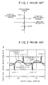
- Fig. 1 shows characteristics of the Coulomb friction in the carriage of the single driving type.
- Each of a moving velocity V and a frictional force F has a plus or minus value according to the moving direction of the carriage.
- a case where the moving velocity V of the carriage changes from the minus value to the plus value will now be considered.
- an almost constant kinetic frictional force F1 of a plus value is generated against the moving velocity.
- a driving force cancelling a static frictional force -F2 is needed and, after moving, the driving force should include a force cancelling an almost constant kinetic frictional force -F1.
- a steep force change of the frictional force acts as a disturbance on a control system.
- a feedback control system with a high bandwidth is generally necessary.
- the reversal of the moving velocity of the carriage occurs, for example, in a track-following control to compensate a repetitive positional deviation of the track due to an eccentricity of the medium. That is, when the carriage is controlled so as to trace the medium eccentricity, the motion of the carriage for the guide rail becomes a reciprocating motion synchronized with an eccentricity period. Therefore, the moving velocity of the carriage is reversed at least twice for one rotation of the medium and is subjected to the disturbance by the steep force change of the frictional force each time.
- Fig. 2 shows a simulation result of a tracking error signal TES for a rotational period (time) when an on-track control is performed by a feedback control system to a head mechanism of a single driving type.
- a track pitch is set to 1.1 ⁇ m
- a rotational speed of the disk is set to 3600 rpm
- a coefficient ⁇ of friction is set to 0.3.
- a band of the feedback control system is set to 1.5 kHz in consideration of a high-order resonance having a higher resonance at about 15 kHz of the actual head mechanism.
- a waveform 200 relates to a case where a peak-to-peak amount of eccentricity is assumed to be 50 ⁇ m.
- a waveform 202 relates to a case where a peak-to-peak amount of eccentricity is assumed to be 20 ⁇ m.
- a waveform 204 relates to a case where a peak-to-peak amount of eccentricity is assumed to be 10 ⁇ m.
- the eccentricity disturbance cannot be sufficiently suppressed due to deterioration of low band error compressing performance and reduction of a control band of the feedback control system due to the single driving of the head mechanism.
- the waveforms are also influenced by the steep change of the frictional disturbance occurring at a point when the moving velocity is equal to 0 when the carriage is allowed to trace the eccentricity, so that large peak-like tracking errors 206-1, 206-2, 206-3, and 206-4 occur. If a Coulomb friction F fric in association with the movement of the carriage is simply expressed by omitting a static friction, it is modeled by the following equation.
- a storage apparatus in which by combining a feedback control system and a learning control system, a steep frictional disturbance due to a medium eccentricity is certainly compensated for, and a tracking error is reduced.
- an optical storage apparatus comprises: a head having a carriage for moving an irradiating position of a laser beam onto an arbitrary track position on a medium; a position signal detecting unit (tracking error detecting unit) for detecting and generating a position signal (tracking error signal) TES according to a positional deviation amount in which a predetermined position of a track on the medium is used as a reference on the basis of the light derived from the medium in accordance with an irradiation of the laser beam; a feedback calculating unit for inputting the position signal TES and calculating a control signal (control current) I FB to move the carriage of the head so as to set the positional deviation amount to zero; and a driving unit (VCM) for driving the carriage of the head so that the irradiating position of the laser beam traces the track on the basis of the control signal I FB of the feedback calculating unit.
- VCM driving unit
- the invention is characterized by comprising a learning control unit for getting an unknown function for one medium rotation to set the positional deviation amount for the repetitive disturbance to zero as an approximated function which was approximately presumed by a learning algorithm and storing it.
- the unknown function for one medium rotation period to set the positional deviation amount for the repetitive disturbance such as a medium eccentricity synchronized with the medium rotation to zero is obtained by a learning algorithm as an approximated function which was approximately presumed by a set of heights of N rectangular functions which a time width of each rectangular function is obtained by dividing the time for one medium rotation period into N intervals and stored.
- a compensation signal of a steep frictional disturbance with a high bandwidth in association with the reverse in the carriage moving direction can be also included in the learning result that is finally obtained.
- a learning control signal By adding such a learning control signal to a feedback control signal as a feed-forward compensation signal, the steep frictional disturbance can be almost cancelled. Since the single driving type carriage is used, there is a limitation due to the existence of the high-order mechanical resonance. Even if the control band is low, a tracking error for the eccentricity of the medium is remarkably reduced and the precision of the on-track control can be improved.
- the learning control unit of the invention is provided between the feedback calculating unit and the driving unit.
- the approximated function is expressed by Îrepeat it is expressed as "I ⁇ repeat" in the specification. This expression is also similarly applied to an approximated function "TES ⁇ repeat".
- the learning control unit When the learning control unit is provided between the feedback calculating unit and the driving unit as mentioned above, since the learning of the drive current of the feedback control system is performed, a learning result of small noises is obtained.
- the learning result can be directly used as a feed-forward current at the time of a seek control, a kickback, or the like after the learning. The control is simpler and more certain because the conversion of the learning result is unnecessary.
- the learning control unit comprises a memory, a sampling unit, an approximated function calculating unit, and a feed-forward output unit.
- the memory has a plurality of memory cells to store the height C i of each rectangular function of the approximated function I ⁇ repeat(t).
- the sampling unit samples the control signal I FB which is outputted from the feedback calculating unit.
- the approximated function calculating unit obtains the height C i of each rectangular function of the approximated function I ⁇ repeat(t) stored in each memory cell of the memory by the following learning law.
- C i Klearn ⁇ I FB
- a feed-forward output unit reads out the height C i , as a learning control signal, of each rectangular function of the approximated function I ⁇ repeat(t) stored in the memory cell of the memory synchronously with the divisional period T of the medium rotation, adds it to the control signal I FB from the feedback calculating unit, and supplies a drive signal I VCM to the driving unit.
- a feed-forward output unit reads out the height C i of each rectangular function of the approximated function I ⁇ repeat(t) stored in the memory cell of the memory synchronously with the sampling period Tsample, adds it to the control signal I FB from the feedback calculating unit, and supplies a drive signal I VCM to the driving unit.
- the feed-forward output unit reads out the value of the approximated function I'repeat(t) stored in each memory cell of the memory corresponding to the time that is advanced by a predetermined time Atlead and outputs it.
- the learning control unit repeats the learning while feed-forward outputting the learning result at this time point.
- the learning control unit is provided between the position signal detecting unit and the feedback calculating unit.
- T L denotes the time corresponding to one medium rotation period
- TES ⁇ repeat(t) where, 0 ⁇ t ⁇ T L ; T L denotes the period for one medium rotation period
- the height C i where, i is the index number; 0 ⁇ i ⁇ (N-1)
- the learning control unit has a memory, a sampling unit, an approximated function calculating unit, and a feed-forward output unit.
- the memory has a plurality of memory cells to store the height C i of each rectangular function of the approximated function TES ⁇ repeat(t).
- the sampling unit samples the position signal TES which is outputted from the position signal detecting unit.
- a feed-forward output unit reads out the height C i of each rectangular function of the approximated function TES ⁇ repeat(t) stored in the memory cell synchronously with the sampling period Tsample, adds it to the position signal TES from the position signal detecting unit, and supplies a feedback signal TES FB to the feedback calculating unit.
- the feed-forward output unit reads out the value of the approximated function TES ⁇ repeat(t) stored in each memory cell of the memory corresponding to the time that is advanced by the predetermined time ⁇ tlead and outputs it.
- the learning control unit outputs the approximated function I ⁇ repeat(t) or TES ⁇ repeat(t) obtained by the learning algorithm after the learning synchronously with the medium rotation, thereby performing a feed-forward control.
- the learning control unit feed-forward controls such that an operation to obtain an approximated function by the learning algorithm is performed for a specific time at a timing just after the medium was inserted into the apparatus and, at the time of a track-following control after the learning, the obtained approximated function is outputted synchronously with the medium rotation and the repetitive disturbance is removed.
- the learning control unit also feed-forward controls such that, at the time of the track jump and the seek control after the learning, the obtained approximated function is outputted synchronously with the medium rotation and the repetitive disturbance is removed.
- the approximated function is obtained by learning at a specific position in the disk radial direction, for example, at a position near the center region on the disk, in the case where a pickup is sought and moved to another radial direction position and the track-following control is performed, there is a situation such that an error occurs so long as the obtained approximated function is used, so that the approximation is inadequate.
- the getting operation of the approximated function is performed at a plurality of positions in correspondence to the radial direction position of the disk.
- the approximated function is selected in accordance with the track address where the pickup is on-tracked at that time (for example, the approximated function obtained by the learning in the nearest track address is selected) and the feed-forward is performed, so that the high precise track-following control can be realized irrespective of the track address to be on-tracked.
- the getting operation of the approximated function is performed at a plurality of positions as mentioned above, there is hardly difference among the basic waveforms of the approximated functions and differences among the approximated functions are fine differences.
- the head has a structure of the single driving type such that the objective lens is mounted onto the carriage that is freely movable in the direction which transverses the tracks on the medium in a manner such that the focusing control can be freely performed, and both the track-following control for allowing the laser beam to trace the track by the movement of the carriage and the seek control for moving the laser beam onto an arbitrary track position are performed.
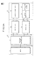
- Figs. 3A and 3B show a storage apparatus of the invention and relates to an optical disk drive as an example.
- the optical disk drive of the invention is constructed by a control unit 10 and an enclosure 11.
- the control unit 10 has: an MPU 12 to perform a whole control of the optical disk drive; an upper interface 17 to transmit and receive commands and data to/from an upper apparatus; an optical disk controller (ODC) 14 to perform processes necessary to read and write data from/to an optical disk medium; a DSP 16; and a buffer memory 18.
- the buffer memory 18 is used in common by the MPU 12, optical disk controller 14, and upper interface 17.
- a formatter and an ECC unit are provided for the optical disk controller 14.
- the formatter divides NRZ write data on a sector unit basis of the medium and forms a recording format, and the ECC unit forms an ECC code on a sector write data unit basis and adds it and, if necessary, forms a CRC code and adds it. Further, sector data which was ECC encoded is converted into, for example, a 1-7 RLL code. At the time of a read access, sector read data is 1-7 RLL inversely converted and subsequently CRC checked by the ECC unit and, thereafter, is subjected to error detection and correction. Further, the NRZ data of the sector unit is coupled by the formatter and transferred to the upper apparatus as a stream of NRZ read data.
- a write LSI 20 is provided for the optical disk controller 14.
- a write modulating unit and a laser diode control unit are provided for the write LSI 20.
- a laser diode unit 30 has a laser diode and a detector for monitoring.
- the write LSI 20 converts write data into data of a data format in the PPM recording or PWM recording (also referred to as a mark recording or edge recording).
- a rewritable MO cartridge medium any of media of 128 MB, 230 MB, 540 MB, 640 MB, 1.3 GB, and the like can be used.
- the pit position recording in which data is recorded in correspondence to the presence or absence of a mark on the medium is used.
- a recording format of the medium is a zone CAV and the number of zones of a user area is equal to 1 in case of the 128MB medium.
- the pulse width recording in which edges of a mark, namely, the front edge and the rear edge are made correspond to data is used.
- a difference between recording capacities of the 640MB medium and 540MB medium is based on a difference of sector capacities.
- the optical disk drive of the invention can cope with the MO cartridges of the storage capacities such as 128 MB, 230 MB, 540 MB, 640 MB, and 1.3 GB, and further, 230 MB, 540 MB, 640 MB, and the like corresponding to the direct overwrite. Therefore, when the MO cartridge is loaded into the optical disk drive, an ID portion of the medium is first read out, the kind of medium is recognized by the MPU 12 from a pit interval, and the recognized kind as a recognition result is notified to the optical disk controller 14.
- a read LSI 24 is provided as a reading system for the optical disk controller 14.
- a read demodulating unit and a frequency synthesizer are built in the read LSI 24.
- a photosensing signal of the return light of the beam from the laser diode by a detector 32 for ID/MO provided for the enclosure 11 is inputted as an ID signal and an MO signal to the read LSI 24 through a head amplifier 34.
- Circuit functions of an AGC circuit, a filter, a sector mark detecting circuit, and the like are provided for the read LSI 24.
- the read LSI 24 forms a read clock and read data from the inputted ID signal and MO signal and demodulates PPM data or PWM data into the original NRZ data.
- the MPU 12 Since the zone CAV is used, the MPU 12 performs a setting control of a frequency division ratio to generate a zone correspondence clock frequency to the frequency synthesizer built in the read LSI 24.
- the frequency synthesizer is a PLL circuit having a programmable frequency divider and generates a reference clock, as a read clock, having a predetermined inherent frequency according to a zone position on the medium. That is, the programmable frequency divider is constructed by the PLL circuit having the programmable frequency divider and the MPU 12 generates a reference clock of a frequency fo according to a frequency division ratio (m/n) set in accordance with the zone number by the following equation.
- a frequency division value n of the denominator of the frequency division ratio (m/n) is an inherent value according to the kind of medium of 128 MB, 230 MB, 540 MB, or 640 MB.
- a frequency division value m of the numerator is a value which changes in accordance with the zone position on the medium and is prepared as table information of the value corresponding to the zone number with respect to each medium.
- the read data demodulated by the read LSI 24 is supplied to the reading system of the optical disk controller 14 and is subjected to the inverse conversion of 1-7RLL.
- the data is subjected to a CRC check and an ECC process by the decoding function of the ECC unit, so that the NRZ sector data is reconstructed. Subsequently, it is converted into a stream of the NRZ read data coupled with the NRZ sector data by the formatter.
- This data stream is transmitted to the upper apparatus via the buffer memory 18 by the upper interface 17.
- a detection signal of a temperature sensor 36 provided on the enclosure 11 side is supplied to the MPU 12 via the DSP 16.
- the MPU 12 controls each of the light emitting powers for reading, writing, and erasing in the laser diode unit 30 to an optimum value on the basis of an environment temperature of the unit in the apparatus detected by the temperature sensor 36.
- the MPU 12 controls a spindle motor 40 provided on the enclosure 11 side by a driver 38 via the DSP 16. Since the recording format of the MO cartridge is the zone CAV, the spindle motor 40 is rotated at a predetermined speed of, for example, 3000 rpm.
- the MPU 12 controls a magnetic field applying unit 44 using an electromagnet provided on the enclosure 11 side through a driver 42 via the DSP 16.
- the magnetic field applying unit 44 is arranged on the side opposite to the beam irradiating side of the MO cartridge loaded in the apparatus and supplies an external magnetic field to the medium at the time of the recording, erasure, or the like.
- the DSP 16 has a servo function to position the beam from the laser diode unit 30 to the medium and performs a seek control (coarse control) and a track-following control (fine control) to seek and move the laser beam to a target track so as to enter an on-track state.
- the seek control and track-following control can be simultaneously executed in parallel with a write access or a read access in response to an upper command by the MPU 12.
- a detector 45 for FES for receiving the beam return light from the medium is provided for the optical unit on the enclosure 12 side.
- An FES detecting circuit (focusing error signal detecting circuit) 46 forms a focusing error signal from a photosensing output of the detector 45 for FES and sends it to the DSP 16.
- a detector 47 for TES having a multidivision (6 division or 9 division) photosensing unit to receive the beam return light from the medium is provided for the optical unit on the enclosure 11 side.
- a TES detecting circuit (tracking error signal detecting circuit) 48 forms a tracking error signal from a photosensing output of the detector 47 for TES and sends it to the DSP 16.
- the tracking error signal is formed by a push-pull method (also referred to as a far field method).
- the tracking error signal is inputted to a TZC detecting circuit (track zero-cross point detecting circuit) 50 and a track zero-cross pulse is formed and inputted to the DSP 16. Further, to control the position of a beam spot on the medium, the DSP 16 controls a focusing actuator 52 and a VCM 54 through drivers 55 and 58.
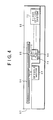
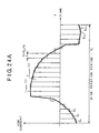
- An outline of the enclosure 11 in the optical disk drive is as shown in Fig. 4.
- the spindle motor 40 is provided in a housing 60. By inserting an MO cartridge 64 from the side of an inlet door 62 to a hub of a rotary shaft of the spindle motor 40, the loading such that an internal MO medium 66 is loaded to a hub of the rotary shaft of the spindle motor 40 is performed.
- the head mechanism is constructed by a carriage 68, an objective lens 70, a fixed optical system 72, and a mirror 74.
- the carriage 68 which can be freely moved by the VCM 54 in the direction which transverses the tracks on the medium is provided below the MO medium 66 of the loaded MO cartridge 64.
- the objective lens 70 is mounted on the carriage 68, allows the beam from a laser diode provided for the fixed optical system 72 to enter through the rising mirror 74, and forms an image of a beam spot onto the medium surface of the MO medium 66.
- the objective lens 70 is moved in the optical axial direction by the focusing actuator 52 shown in the enclosure 11 in Figs. 3A and 3B.
- the laser beam can be moved in the radial direction which transverses the tracks on the medium by the linear driving of the carriage 68 by the VCM 54.
- the carriage 68 is supported by a slide bearing to two guide rails which are fixedly arranged and simultaneously performs a seek control called a coarse control for moving the laser beam to an arbitrary track position and a track-following control known as a fine control for allowing the laser beam to trace the track center at the sought track position.
- a seek control called a coarse control for moving the laser beam to an arbitrary track position
- a track-following control known as a fine control for allowing the laser beam to trace the track center at the sought track position.
- a head mechanism of the single driving type as mentioned above, a mechanism disclosed in, for example, JP-A-9-312026, JP-A-9-54960, or the like can be used.
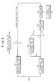
- Fig. 5 shows the first embodiment of a feedback control system of the head mechanism in the storage apparatus of the invention.
- the first embodiment is characterized in that the learning control unit is provided between a feedback control unit and a carriage driving unit.
- the feedback control system of the head mechanism comprises: a tracking error detecting unit 78; a feedback control unit 80; a learning control unit 82; an adder 84; a carriage driving unit 86; and a carriage 88.
- the tracking error detecting unit 78 generates the tracking error signal TES showing a positional deviation amount for the track center from the return light by the irradiation of the laser beam to the medium by an objective lens mounted on the carriage 88. As shown in Fig.
- the tracking error detecting unit 78 optically detects and outputs the tracking error as a difference between the track position which is fluctuated by the eccentricity of the medium and the position of the laser beam.
- the feedback control unit 80 moves the carriage 88 by the carriage driving unit 86 so as to eliminate the deviation amount of the laser beam for the track center by setting the tracking error signal TES to zero.
- the feedback control unit 80 generates the control signal I FB by, for example, a PID arithmetic operation.
- the control signal I FB becomes a feedback current instruction value for the carriage driving unit 86 using the VCM 54 shown in Figs. 3A and 3B.
- the learning control unit 82 receives the control signal I FB as a feedback current instruction value outputted from the feedback control unit 80 and gets a learning control signal I ⁇ repeat, by a learning law, as an approximated function of an unknown drive current function Irepeat to suppress a tracking error caused by such as repetitive frictional disturbance, eccentricity disturbance, or the like in association with the eccentric rotation of the medium.
- the learning control signal I ⁇ repeat obtained as a learning result is outputted synchronously with the medium rotation.
- the learning control signal I ⁇ repeat is added as a feed-forward control signal to the control signal I FB from the feedback control unit 80 by the adder 84, so that a drive signal I VCM is derived.
- I VCM drives the carriage 88 through the carriage driving unit 86.
- a large frictional disturbance whose direction changes in an instant at a point when the moving velocity is equal to zero as shown in Fig. 1 is periodically applied to the carriage 88 as a force disturbance 90.
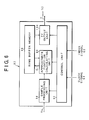
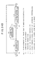
- Fig. 6 is a functional block diagram of the learning control unit 82 in Fig. 5.
- the learning control unit 82 comprises: a control unit 92; a sample processing unit 94; an approximated function calculating unit 96, a ring buffer memory 98; and a feed-forward output unit (hereinafter, referred to as an "FF output unit") 100.
- a clock signal El and an index signal E2 which is obtained synchronously with one rotation of the medium are inputted to the control unit 92.
- the control unit 92 sets
- the time t is reset by the index signal which is obtained at a certain time in every medium rotation, so that it has a value of 0 ⁇ t ⁇ T L .
- the learning is progressed in accordance with the following equation by integrating the control signal I FB corresponding to each rectangular function.
- Klearn in the equation (3) denotes a learning gain and is a positive constant.
- the value of i is determined in accordance with the value of t, namely, the height C i as a learning target is selected, and an integration arithmetic operation using the value I FB (t) of the control signal at that time as an input is executed.
- the height of each rectangular function is sequentially integrated until the value of I FB as an input of the learning law is equal to almost zero. Therefore, after the settlement of the learning, the approximated function I ⁇ repeat(t) which is expressed by the rectangular functions C 0 to C N-1 becomes a function which approximates Irepeat(t) as an unknown drive current function.
- the height C i of each rectangular function obtained by the learning law of the equation (3) has been stored in a relevant memory cell in the ring buffer memory 98.
- Fig. 8 shows a memory construction of the ring buffer memory 98 provided for the learning control unit 82 in Fig. 6.
- the ring buffer memory 98 has N memory cells 106-0 to 106-(N-1) in correspondence to the number N of division of the period T L for one medium rotation period.
- the value of the height C i of each rectangular function calculated by the equation (3) synchronously with the disk rotation is stored as mem[i] into a cell address (i) of the memory cells 106-0 to 106-(N-1).
- the time t shown in correspondence to the positions of the memory cells 106-0 to 106-(N-1) in the ring buffer memory 98 is time which is reset by the index signal obtained at a certain time in every medium rotation.
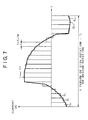
- the time width T of each rectangular function shown in Fig. 7 is set to a longer width as compared with the sampling period Tsample of the input signal I FB by the sample processing unit 94 in Fig. 6.
- the rotational speed of the medium is equal to 4500 rpm
- its rotating frequency is equal to 75 Hz
- the arithmetic operation results which are stored into the memory cells 106-0 to 106-(N-1) in Fig. 8 are based on the integration arithmetic operation in which the learning gain Klearn is used as an integration gain and the control signal I FB is used as an input. That is, it is a process for reading out the learning result mem[i] previously stored in the memory cell in the corresponding address (i), adding ⁇ Klearn ⁇ Tsample ⁇ I FB (t) ⁇ calculated at every sampling timing to the read-out learning result mem[i], and storing an addition result after that.
- the value of mem[i] is not updated.
- the integration arithmetic operation of the equation (5) is further performed by using the integration result up to the previous rotation which has already been stored in mem[i] as an initial value.
- the FF output unit 100 simultaneously with the integrating process in the corresponding memory cell in the ring buffer memory 98 of the calculation result of the approximated function calculating unit 96 according to the equation (5), the FF output unit 100 likewise performs a feed-forward control such that the calculation result of the corresponding memory cell in the ring buffer memory 98 is read out and it is added by the adder 84 in Fig.
- the approximated function calculating unit 96 in Fig. 6 calculates the cell address (i) by the equation (4) and performs the storage of the calculation result C i into the ring buffer memory 98 by the approximated function calculating unit 96 by the output of an address control signal and the reading and output of the learning result at that time to the FF output unit 100.
- the learning control unit 82 in Fig. 6 shifts the operating mode to the learning result output mode.
- the control unit 92 makes the ring buffer memory 98 and FF output unit 100 operative and performs the feed-forward control such that the learning control signal I ⁇ repeat as a learning result stored in each memory cell is read out from the ring buffer memory 98, for example, at the same reading period as the sampling period Tsample in the learning mode synchronously with the index signal E2 that is obtained every medium rotation, the read-out signal I ⁇ repeat is outputted to the adder 84 in Fig.
- the drive current I VCM is supplied to the carriage driving unit 88, and the carriage 88 is drived so that the repetitive frictional disturbance is suppressed in association with the medium eccentricity.
- the selection of the memory cell for the feed-forward output by the FF output unit 100 is calculated by the following equations when it is assumed that the advanced time is labelled as ⁇ tlead.
- the memory cell number i is determined on the basis of the time obtained by adding the lead time ⁇ tlead to the time t.
- the memory cell number i is calculated in accordance with the calculation as shown in the second equation of the equations (6). That is, the reading position is returned to the head in the ring buffer and the data is read out from an instance when t exceeds (T L - ⁇ tlead).
- Fig. 9 is a flowchart for a positioning control in the storage apparatus of the invention having the learning control unit 82 in Fig. 5.
- step S1 when the medium is loaded into the apparatus, a medium loading process according to a predetermined medium loading sequence is executed in step S2.
- step S3 In the medium loading process, a process in the learning mode in step S3 by the learning control unit 82 newly provided in the invention is executed.
- the end of the learning process in the learning mode is discriminated by
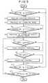
- Fig. 10 is a flowchart for the learning process in the learning mode in the learning control unit 82 in Fig. 6.
- the presence or absence of the index which is obtained every rotation of the medium is first checked in step S1.
- the address (i) of the memory cell is calculated from the time t at that time in step S5 on the basis of the equation (4).
- the storage value mem[i] of the cell address (i) is read out in step S6.
- step S7 a new storage value mem[i] is subsequently calculated in accordance with the equation (5).
- the newly calculated storage value is stored into the memory cell and updated in step S8.
- step S9 the previous storage value in the cell address calculated by the equation (6), namely, the cell address that is preceding by the lead time ⁇ tlead is read out and feed-forward outputted to the feedback control system.
- the processes in steps S1 to S9 as mentioned above are repeated until a learning end condition is satisfied, for example, the present time reaches a preset learning time in step S10.
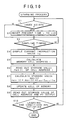
- Fig. 11 is a flowchart for a feed-forward outputting process in the learning result output mode of the learning control unit 82 in Fig. 6.
- the feed-forward outputting process the presence or absence of the index which is obtained every medium rotation is discriminated in step S1.
- Whether the present time is an output timing or not is discriminated in step S3. It is assumed that the output timing is, for example, a timing that is determined by the same output period as the sampling period Tsample in the learning mode in Fig. 9.
- step S3 When the output timing is discriminated in step S3, the address (i) in the memory cell based on the time obtained by adding an advanced (a lead) time ⁇ tlead to the present time t by the equation (6) is calculated in step S4.
- step S5 the storage value in the cell address is read out and feed-forward outputted to the feedback control system. If there is a medium ejection in step S6 or if there is an end instruction of the apparatus in step S7, the feed-forward output is finished.
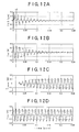
- Figs. 12A to 12D are waveform explanatory diagrams of the tracking error signal TES, feedback control signal I FB , learning control signal I ⁇ repeat, and carriage drive signal I VCM for a period of time from the start of the learning to the end thereof by the learning control unit 82 in the first embodiment of Fig. 5.
- An axis of abscissa indicates the time by seconds.
- Fig. 12A shows the tracking error signal TES.
- Fig. 12B shows the feedback control signal I FB .
- Fig. 12C shows the learning control signal I ⁇ repeat.
- Fig. 12D shows the carriage drive signal I VCM .
- the learning process is started from time t0.
- the tracking error signal TES in Fig. 12A shows a large positional deviation due to the peak-like frictional disturbance and the eccentricity occurring at the zero moving velocity of the carriage in association with the medium eccentricity.
- the tracking error signal TES gradually attenuates in association with the progress of the learning and the frictional disturbance and the positional deviation are finally suppressed.
- the learning control signal I ⁇ repeat is the initial value of zero of the learning because it is read out from the cell for ⁇ tlead future from the cell that is currently updated.
- the learning process from time t0 is a process such that the disturbance component included in the feedback control signal I FB in Fig.
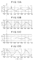
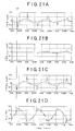
- Figs. 13A to 13D enlargedly show a learning start portion corresponding to the time within a range from 0.01 to 0.05 sec in Figs. 12A to 12D on the basis of the time base.
- the learning is started from time t0 in the figures.
- the tracking error due to the large eccentricity of the medium and the peak-like tracking error due to the steep change of frictional disturbance at the zero moving velocity of the carriage occur in Fig. 13A.
- Figs. 14A to 14D enlargedly show waveforms on the way of the learning within a time range from 0.1 to 0.14 sec in Figs. 12A to 12D on the basis of the time base.
- the waveforms on the way of the learning in Figs. 14A to 14D as compared with those at the start of the learning in Figs. 13A to 13D, most of the disturbance component of the feedback control signal I FB in Fig. 14B is transferred into the learning control signal I'repeat in Fig. 14C as a learning result.
- the peak-like positional deviation due to the steep change of frictional disturbance of the tracking error signal TES in Fig. 14A is mostly suppressed.
- the positional deviation due to the eccentricity is also mostly suppressed.
- Figs. 15A to 15D are waveform diagrams in which the waveforms near the learning end portion within a time range from 0.2 to 0.25 sec in Figs. 13A to 13D are enlarged on the basis of the time base.
- the disturbance component is almost perfectly transferred into the learning control signal I ⁇ repeat in Fig. 15C and the disturbance of the tracking error signal TES in Fig. 15A serving as a feedback signal of the feedback control system is suppressed to a level such that it can be almost ignored.
- Figs. 16A to 16C are waveforms of respective units in the learning process in the case where the compensation of the advanced time Atlead to compensate the delay time of the feedback control system is not performed by the FF output unit 100 of the learning control unit 82 in Fig. 6.
- Figs. 17A to 17C enlargedly show waveforms at the timing near the end of the learning within a time range from 0.2 to 0.25 sec in Figs. 16A to 16C on the basis of the time base.
- the waveforms of the tracking error signal TES, learning control signal I ⁇ repeat, and carriage drive signal I VCM are shown here and the feedback control signal I FB is omitted.
- the memory cell to be updated by the learning law and the memory cell to be outputted as the learning result are the same, so that an output of the learning control signal I ⁇ repeat is obtained from the beginning at t0.
- the response waveform becomes oscillatory by being influenced by the delay time of the feedback control system.
- the oscillatory component due to the delay is also transferred as a learning result into the learning control signal I ⁇ repeat which is outputted as a learning result in Fig. 17C at the learning end time point.
- the enough disturbance component suppressing effect cannot be expected.
- good learning results as shown in Figs. 12A to 15D are obtained by the output of the learning result by the setting of the advanced time corresponding to the delay time of the feedback control system in the FF output unit 100 in Fig. 6.
- the feedback current itself which is outputted from the feedback control unit 80 to the carriage driving unit 86 is a learning target, the waveforms with a few noises can be learned. Since the learning result is the feedback current itself, there is an advantage such that it can be directly outputted as a feed-forward current to the feedback control system and used at the time of the seek control, on-track control, kickback control, or the like.
- Fig. 18 shows the second embodiment of a positioning control of the head of the storage apparatus of the invention.
- the second embodiment is characterized in that the learning control unit is provided between a tracking error detecting unit and a feedback control unit.
- the feedback control section is constructed by the a tracking error detecting unit 78, feedback control unit 80, carriage driving unit 86, and carriage 88.
- the tracking error detecting unit 78 optically detects and outputs the tracking error as a difference between the track position which is fluctuated by the eccentricity of the medium and the position of the laser beam.
- the force disturbance 90 such as a frictional disturbance which is inverted at the timing of the zero moving velocity in the reciprocating motion of the carriage in association with the eccentricity disturbance is applied to the carriage 88.
- a learning control unit 104 is provided between the tracking error detecting unit 78 and feedback control unit 80, and the tracking error signal TES from the tracking error detecting unit 78 is inputted to the learning control unit 104 and is subjected to the learning process.
- the learning tracking error signal TES'repeat obtained as a learning result is added to the tracking error signal TES from the tracking error detecting unit 78 by an addition point 105.
- a resultant addition signal is inputted as a feedback signal TES FB to the feedback control unit 80.
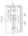
- Fig. 19 is a functional block diagram of the learning control unit 104 in Fig. 18.
- a fundamental construction other than the construction such that the tracking error signal TES is inputted and learned and the learned tracking error signal TES ⁇ repeat is outputted as a learning control signal, is the same as that of the first embodiment of Fig. 6. That is, the learning control unit 104 is constructed by the control unit 92, sample processing unit 94, approximated function calculating unit 96, ring buffer memory 98, and FF output unit 100.
- a cell address calculating unit to designate a cell position in the ring buffer memory 98 is provided in the control unit 92. According to a learning algorithm by the learning control unit 104 in Fig.
- a time function for one rotation period of the medium is defined for the tracking error signal TES as a learning target in place of the periodic feedback current in the first embodiment shown in Fig. 7, and an approximated function TES ⁇ repeat(t) is similarly obtained as a set of the heights of the rectangular functions obtained by dividing the rotation period into N intervals.
- the approximated function which is approximated by the set of the heights of rectangular functions obtained by dividing the period T L for one medium rotation period into N intervals is as shown by the following equation.
- An address calculation to store the learning result into the corresponding memory cell in the ring buffer memory 98 is executed in accordance with the equation (4) in a manner similar to the case of the first embodiment.
- the cell address when the calculation result is outputted by the FF output unit 100 is obtained in accordance with the equation (6) by the lead time ⁇ tlead in consideration of the delay time of the feedback control system in a manner similar to the first embodiment.
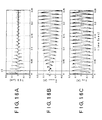
- Figs. 20A to 20D are signal waveforms of respective sections in the learning mode in the second embodiment to learn the tracking error signal TES in Figs. 18 and 19.
- Fig. 20A shows the tracking error signal TES.
- Fig. 20B shows the learning tracking error signal TES ⁇ repeat which is outputted as a learning result.
- Fig. 20C shows the feedback signal TES FB serving as an input of the feedback control unit 80.
- Fig. 20D shows the carriage drive current I VCM . In Figs. 20A to 20D as well, the learning is started at time t0.
- the tracking error due to the eccentricity disturbance and the peak-like tracking error due to the steep change of the frictional disturbance in association with the zero moving velocity of the carriage are included in the tracking error signal TES in Fig. 20A.
- the disturbance component is transferred into the learning tracking error signal TES ⁇ repeat in Fig. 20B in association with the progress of the learning and the disturbance component of the tracking error signal TES is sufficiently suppressed at the end of the learning.
- Figs. 21A to 21D enlargedly show waveforms at the time near the start of the learning within a time range from 0.01 to 0.05 sec in Figs. 20A to 20D on the basis of the time base. That is, the learning is started at time t0. Immediately after the start of the learning, the eccentricity disturbance and the peak-like frictional disturbance occurring at the timing of the zero moving velocity of the carriage are included in the tracking error signal TES in Fig. 22A.
- the advance compensation by the advanced time ⁇ tlead to perform the delay compensation of the feedback control system is performed when the learning result is read out from the ring buffer memory 98 by the FF output unit 100 in Fig. 19.
- Figs. 22A to 22D enlargedly show the waveforms in respective sections on the way of the learning within a time range from 0.1 to 0.14 sec in Fig. 19 on the basis of the time base.
- Figs. 23A to 23D enlargedly show waveforms at the time near the end of the learning within a time range from 0.2 to 0.25 sec in Figs. 20A to 20D on the basis of the time base.
- almost all of the disturbance components included in the tracking error signal TES in Fig. 23A are transferred into the learning tracking error signal TES ⁇ repeat as a learning result of Fig. 23B, so that a control environment in which the disturbance due to the medium eccentricity does not exist in the feedback control system is formed.
- Fig. 24A shows a principle of an approximating method of an unknown function.
- Fig. 24B shows a constructional principle diagram of a control system according to the invention.
- the control system comprises the adder 76, feedback control unit 80, learning control unit 82, adder 84, and single-stage tracking mechanism 110.
- a solid bold line in Fig. 24A indicates an unknown VCM drive current signal Irepeat(t) which can suppress the repetitive disturbance synchronized to the disk rotation.
- the time t which is used in the diagram and the following equations (10) to (12) is the time synchronized to the disk rotation, and is reset to zero at a certain time in every rotation period of the disk. That is, now assuming that T L denotes the disk rotation period, 0 ⁇ t ⁇ T L is obtained.
- the learning control unit 82 outputs the feed-forward signal I FF (t) as follows.
- Fig. 24A shows the principle of the approximating method of an unknown function.
- Fig. 24B shows the constructional principle diagram of the control system according to the invention.
- the control system comprises the adder 76, feedback control unit 80, learning control unit 82, adder 84, and single-stage tracking mechanism 110.
- a solid bold line in Fig. 24A indicates an unknown VCM drive current signal Irepeat(t) which can suppress the repetitive disturbance synchronized to the disk rotation.
- the time t which is used in the diagram and the following equations (13) to (16) is the time synchronized to the disk rotation, and is reset to zero at a certain time in every rotation period of the disk. That is, now assuming that T L denotes the disk rotation period, 0 ⁇ t ⁇ T L is obtained.
- the learning control unit 82 outputs the feed-forward signal I FF (t) as follows.
- the learning control signal to suppress the disturbance component is obtained by the learning control of the feedback control signal or the tracking error signal.
- the eccentricity positional deviation, the peak-like tracking error due to the steep change of the frictional disturbance, and the like can be effectively suppressed by the feed-forward output for the feedback control system of the learning result obtained by the learning control without widening the band of the feedback control system.
- the control precision and response speeds of the feedback control system in the seek control and the track-following control can be remarkably improved.
Landscapes
- Optical Recording Or Reproduction (AREA)
- Feedback Control In General (AREA)
- Moving Of The Head To Find And Align With The Track (AREA)
Applications Claiming Priority (6)
| Application Number | Priority Date | Filing Date | Title |
|---|---|---|---|
| JP36632698 | 1998-12-24 | ||
| JP36632698 | 1998-12-24 | ||
| JP7504399 | 1999-03-19 | ||
| JP7504399 | 1999-03-19 | ||
| JP30824499 | 1999-10-29 | ||
| JP30824499A JP3559209B2 (ja) | 1998-12-24 | 1999-10-29 | 記憶装置 |
Publications (2)
| Publication Number | Publication Date |
|---|---|
| EP1014366A2 true EP1014366A2 (fr) | 2000-06-28 |
| EP1014366A3 EP1014366A3 (fr) | 2001-01-03 |
Family
ID=27301689
Family Applications (1)
| Application Number | Title | Priority Date | Filing Date |
|---|---|---|---|
| EP99123659A Withdrawn EP1014366A3 (fr) | 1998-12-24 | 1999-11-29 | Appareil de stockage |
Country Status (4)
| Country | Link |
|---|---|
| US (1) | US6628579B2 (fr) |
| EP (1) | EP1014366A3 (fr) |
| JP (1) | JP3559209B2 (fr) |
| CN (1) | CN1128441C (fr) |
Cited By (3)
| Publication number | Priority date | Publication date | Assignee | Title |
|---|---|---|---|---|
| EP1182652A3 (fr) * | 2000-08-26 | 2003-06-04 | Samsung Electronics Co., Ltd. | Dispositif et procédé pour la compensation de perturbations, et système d'asservissement pour des supports d'enregistrement optique utilisant ce dispositif et ce procédé |
| US6721247B2 (en) | 2000-07-10 | 2004-04-13 | Fujitsu Limited | Disk apparatus and track following control method |
| WO2006117278A1 (fr) * | 2005-04-29 | 2006-11-09 | Thomson Licensing | Procede et arrangement destines a corriger des ecarts de regulation dans une boucle de regulation presentant des changements de valeur de regulation cycliques |
Families Citing this family (18)
| Publication number | Priority date | Publication date | Assignee | Title |
|---|---|---|---|---|
| FR2805610B1 (fr) * | 2000-02-28 | 2002-04-19 | Schneider Electric Ind Sa | Detecteur pour controle de rotation |
| EP1301925B1 (fr) * | 2000-07-12 | 2004-02-25 | Disccontrol APS | Procede de lecture amelioree d'un disque de donnees numeriques |
| JP3762629B2 (ja) | 2000-09-29 | 2006-04-05 | 富士通株式会社 | トラックジャンプ方法及び記憶装置 |
| JP3795738B2 (ja) * | 2000-09-29 | 2006-07-12 | 富士通株式会社 | 記録媒体の回転制御方法及び記憶装置 |
| KR100393061B1 (ko) | 2000-12-29 | 2003-07-31 | 삼성전자주식회사 | 디스크 드라이브 시스템의 액튜에이터 주파수 응답 특성을이용한 편심 보정 장치 |
| JP2002245738A (ja) * | 2001-02-15 | 2002-08-30 | Fujitsu Ltd | ディスク装置及び外乱補償方法 |
| JP2002358678A (ja) * | 2001-05-31 | 2002-12-13 | Fujitsu Ltd | トラックサーボ制御方法、トラックサーボ制御装置及び光記憶装置 |
| KR100408288B1 (ko) | 2001-06-20 | 2003-12-03 | 삼성전자주식회사 | 편심 보상을 위한 디스크 드라이브 서보 시스템 및 외란보상 방법 |
| WO2003009290A1 (fr) * | 2001-07-17 | 2003-01-30 | Fujitsu Limited | Procede et dispositif de commande de suivi de tete et memoire comprenant ledit dispositif |
| JP4160284B2 (ja) | 2001-09-12 | 2008-10-01 | 松下電器産業株式会社 | 光デイスク装置及びフォーカス制御方法 |
| TW563116B (en) * | 2002-03-29 | 2003-11-21 | Via Tech Inc | Tracking correction method and device for CD drive |
| JP4206354B2 (ja) | 2004-03-30 | 2009-01-07 | 富士通株式会社 | 光ディスク装置 |
| JP2007066451A (ja) * | 2005-08-31 | 2007-03-15 | Fujitsu Ltd | 光ディスク装置 |
| JP4959351B2 (ja) | 2007-01-23 | 2012-06-20 | 富士通株式会社 | ホログラム記録装置およびホログラム記録方法 |
| CN102067213A (zh) * | 2008-06-20 | 2011-05-18 | 松下电器产业株式会社 | 焦点位置控制装置和具有其的光盘装置以及焦点位置控制方法 |
| US11199824B2 (en) | 2012-01-17 | 2021-12-14 | Fisher-Rosemount Systems, Inc. | Reducing controller updates in a control loop |
| US10423127B2 (en) | 2012-01-17 | 2019-09-24 | Fisher-Rosemount Systems, Inc. | Velocity based control in a non-periodically updated controller |
| US9298176B2 (en) * | 2012-01-17 | 2016-03-29 | Fisher-Rosemount Systems, Inc. | Compensating for setpoint changes in a non-periodically updated controller |
Family Cites Families (14)
| Publication number | Priority date | Publication date | Assignee | Title |
|---|---|---|---|---|
| JPS5960740A (ja) | 1982-09-29 | 1984-04-06 | Toshiba Corp | 光デイスク装置 |
| US4616276A (en) * | 1985-07-16 | 1986-10-07 | International Business Machines Corporation | Disk file servo control system with fast reduction of repeatable head position error |
| US4866688A (en) * | 1985-12-20 | 1989-09-12 | Hitachi, Ltd. | Composite tracking servo system for optical disc apparatus with track offset correction |
| JPS62183040A (ja) | 1986-02-07 | 1987-08-11 | Hitachi Ltd | 情報記録デイスクのトラツキングサ−ボ装置 |
| US5065263A (en) * | 1988-05-20 | 1991-11-12 | Matsushita Electric Industrial Co., Ltd. | Track following transducer position control system for a disk storage drive system |
| JPH02108286A (ja) | 1988-10-17 | 1990-04-20 | Matsushita Electric Ind Co Ltd | トラック追従制御装置 |
| US5072318A (en) * | 1990-02-13 | 1991-12-10 | International Business Machines Corporation | Disk file with adaptive cancellation of nonrepeatable disk runout |
| ES2129414T3 (es) * | 1990-09-18 | 1999-06-16 | Rodime Plc | Sistema de control digital para unidades de disco. |
| US5268834A (en) | 1991-06-24 | 1993-12-07 | Massachusetts Institute Of Technology | Stable adaptive neural network controller |
| JPH0714195A (ja) * | 1993-06-29 | 1995-01-17 | Hitachi Ltd | 光ディスク装置のトラックフォローイング装置 |
| JPH0877589A (ja) | 1994-09-05 | 1996-03-22 | Mitsubishi Electric Corp | 光ディスク装置 |
| US5608586A (en) * | 1994-10-21 | 1997-03-04 | International Business Machines Corporation | Robust servo for disk-shift compensation in rotating storage system |
| US5898286A (en) * | 1997-01-13 | 1999-04-27 | International Business Machines Corporation | Digital servo control system for a data recording disk file with improved saturation modelling |
| JP3730372B2 (ja) * | 1997-08-05 | 2006-01-05 | 富士通株式会社 | 光学的記憶装置 |
-
1999
- 1999-10-29 JP JP30824499A patent/JP3559209B2/ja not_active Expired - Fee Related
- 1999-11-29 EP EP99123659A patent/EP1014366A3/fr not_active Withdrawn
- 1999-12-06 US US09/454,627 patent/US6628579B2/en not_active Expired - Fee Related
- 1999-12-16 CN CN99126773.7A patent/CN1128441C/zh not_active Expired - Fee Related
Cited By (5)
| Publication number | Priority date | Publication date | Assignee | Title |
|---|---|---|---|---|
| US6721247B2 (en) | 2000-07-10 | 2004-04-13 | Fujitsu Limited | Disk apparatus and track following control method |
| EP1182652A3 (fr) * | 2000-08-26 | 2003-06-04 | Samsung Electronics Co., Ltd. | Dispositif et procédé pour la compensation de perturbations, et système d'asservissement pour des supports d'enregistrement optique utilisant ce dispositif et ce procédé |
| SG99943A1 (en) * | 2000-08-26 | 2003-11-27 | Samsung Electronics Co Ltd | Apparatus and method of compensating for disturbance using learning control in optical recording/reproducing apparatus and optical recording medium drive servo system using the apparatus and method |
| US6813227B2 (en) | 2000-08-26 | 2004-11-02 | Samsung Electronics Co., Ltd. | Apparatus and method to compensate for disturbance using learning control in an optical recording/reproducing apparatus and optical recording medium drive servo system |
| WO2006117278A1 (fr) * | 2005-04-29 | 2006-11-09 | Thomson Licensing | Procede et arrangement destines a corriger des ecarts de regulation dans une boucle de regulation presentant des changements de valeur de regulation cycliques |
Also Published As
| Publication number | Publication date |
|---|---|
| EP1014366A3 (fr) | 2001-01-03 |
| US20030072226A1 (en) | 2003-04-17 |
| US6628579B2 (en) | 2003-09-30 |
| CN1258066A (zh) | 2000-06-28 |
| JP2000339729A (ja) | 2000-12-08 |
| CN1128441C (zh) | 2003-11-19 |
| JP3559209B2 (ja) | 2004-08-25 |
Similar Documents
| Publication | Publication Date | Title |
|---|---|---|
| US6628579B2 (en) | Storage apparatus | |
| US6370094B1 (en) | Optical storage apparatus | |
| US6628576B1 (en) | Storage apparatus having device for controlling track jump of a positioner | |
| EP0803864B1 (fr) | Appareil de mémoire optique | |
| US6157599A (en) | Optical storage apparatus | |
| US6249496B1 (en) | Optical storage apparatus | |
| US7345972B2 (en) | Rotation control method and storage apparatus | |
| US6381204B1 (en) | Power save mode control method and storage unit | |
| JP3490622B2 (ja) | トラッキング制御方法及び記憶装置 | |
| JP3758412B2 (ja) | 光記憶装置とフォーカスサーボ制御方法 | |
| US6804183B2 (en) | Rotation control method for controlling rotation of media having zones in radial direction and employing ZCAV system, and storage apparatus using the rotation control method | |
| US6628575B1 (en) | Track jump method for ZCAV system and storage apparatus employing ZCAV system | |
| JPH11265513A (ja) | 光学的記憶装置 | |
| US6628581B1 (en) | Servo control method and servo controller of a storage device, and its storage device | |
| JP4153498B2 (ja) | 光学的記憶装置 | |
| JP3832746B2 (ja) | 光学的記憶装置 | |
| JP2740255B2 (ja) | 光ディスク駆動装置 | |
| JPH06325554A (ja) | アクセス制御装置及び制御方法 | |
| US20020186623A1 (en) | Magneto-optical recording medium processing apparatus | |
| JP2002288952A (ja) | トラッキングサーボシステムの方法と装置 | |
| JPH05189776A (ja) | 光学式記録再生装置の光学ヘッド制御方式 | |
| JPH07272421A (ja) | 光ディスク装置 |
Legal Events
| Date | Code | Title | Description |
|---|---|---|---|
| PUAI | Public reference made under article 153(3) epc to a published international application that has entered the european phase |
Free format text: ORIGINAL CODE: 0009012 |
|
| AK | Designated contracting states |
Kind code of ref document: A2 Designated state(s): DE FR GB |
|
| AX | Request for extension of the european patent |
Free format text: AL;LT;LV;MK;RO;SI |
|
| PUAL | Search report despatched |
Free format text: ORIGINAL CODE: 0009013 |
|
| AK | Designated contracting states |
Kind code of ref document: A3 Designated state(s): AT BE CH CY DE DK ES FI FR GB GR IE IT LI LU MC NL PT SE |
|
| AX | Request for extension of the european patent |
Free format text: AL;LT;LV;MK;RO;SI |
|
| RIC1 | Information provided on ipc code assigned before grant |
Free format text: 7G 11B 21/10 A, 7G 11B 7/095 B, 7G 11B 5/596 B, 7G 11B 21/08 B |
|
| AKX | Designation fees paid | ||
| 17P | Request for examination filed |
Effective date: 20010623 |
|
| RBV | Designated contracting states (corrected) |
Designated state(s): DE FR GB |
|
| REG | Reference to a national code |
Ref country code: DE Ref legal event code: 8566 |
|
| 17Q | First examination report despatched |
Effective date: 20060613 |
|
| 17Q | First examination report despatched |
Effective date: 20060613 |
|
| GRAP | Despatch of communication of intention to grant a patent |
Free format text: ORIGINAL CODE: EPIDOSNIGR1 |
|
| STAA | Information on the status of an ep patent application or granted ep patent |
Free format text: STATUS: THE APPLICATION IS DEEMED TO BE WITHDRAWN |
|
| 18D | Application deemed to be withdrawn |
Effective date: 20080826 |