EP1014518B1 - Oscillateur laser à impulsions pour un standard de fréquence atomique - Google Patents
Oscillateur laser à impulsions pour un standard de fréquence atomique Download PDFInfo
- Publication number
- EP1014518B1 EP1014518B1 EP99125101A EP99125101A EP1014518B1 EP 1014518 B1 EP1014518 B1 EP 1014518B1 EP 99125101 A EP99125101 A EP 99125101A EP 99125101 A EP99125101 A EP 99125101A EP 1014518 B1 EP1014518 B1 EP 1014518B1
- Authority
- EP
- European Patent Office
- Prior art keywords
- frequency
- atomic
- resonance frequency
- laser pulse
- oscillator
- Prior art date
- Legal status (The legal status is an assumption and is not a legal conclusion. Google has not performed a legal analysis and makes no representation as to the accuracy of the status listed.)
- Expired - Lifetime
Links
Images




Classifications
-
- H—ELECTRICITY
- H01—ELECTRIC ELEMENTS
- H01S—DEVICES USING THE PROCESS OF LIGHT AMPLIFICATION BY STIMULATED EMISSION OF RADIATION [LASER] TO AMPLIFY OR GENERATE LIGHT; DEVICES USING STIMULATED EMISSION OF ELECTROMAGNETIC RADIATION IN WAVE RANGES OTHER THAN OPTICAL
- H01S3/00—Lasers, i.e. devices using stimulated emission of electromagnetic radiation in the infrared, visible or ultraviolet wave range
- H01S3/05—Construction or shape of optical resonators; Accommodation of active medium therein; Shape of active medium
- H01S3/06—Construction or shape of active medium
- H01S3/063—Waveguide lasers, i.e. whereby the dimensions of the waveguide are of the order of the light wavelength
- H01S3/067—Fibre lasers
- H01S3/06791—Fibre ring lasers
-
- G—PHYSICS
- G04—HOROLOGY
- G04F—TIME-INTERVAL MEASURING
- G04F5/00—Apparatus for producing preselected time intervals for use as timing standards
- G04F5/14—Apparatus for producing preselected time intervals for use as timing standards using atomic clocks
-
- H—ELECTRICITY
- H01—ELECTRIC ELEMENTS
- H01S—DEVICES USING THE PROCESS OF LIGHT AMPLIFICATION BY STIMULATED EMISSION OF RADIATION [LASER] TO AMPLIFY OR GENERATE LIGHT; DEVICES USING STIMULATED EMISSION OF ELECTROMAGNETIC RADIATION IN WAVE RANGES OTHER THAN OPTICAL
- H01S3/00—Lasers, i.e. devices using stimulated emission of electromagnetic radiation in the infrared, visible or ultraviolet wave range
- H01S3/10—Controlling the intensity, frequency, phase, polarisation or direction of the emitted radiation, e.g. switching, gating, modulating or demodulating
- H01S3/13—Stabilisation of laser output parameters, e.g. frequency or amplitude
- H01S3/139—Stabilisation of laser output parameters, e.g. frequency or amplitude by controlling the mutual position or the reflecting properties of the reflectors of the cavity, e.g. by controlling the cavity length
- H01S3/1394—Stabilisation of laser output parameters, e.g. frequency or amplitude by controlling the mutual position or the reflecting properties of the reflectors of the cavity, e.g. by controlling the cavity length by using an active reference, e.g. second laser, klystron or other standard frequency source
-
- H—ELECTRICITY
- H01—ELECTRIC ELEMENTS
- H01S—DEVICES USING THE PROCESS OF LIGHT AMPLIFICATION BY STIMULATED EMISSION OF RADIATION [LASER] TO AMPLIFY OR GENERATE LIGHT; DEVICES USING STIMULATED EMISSION OF ELECTROMAGNETIC RADIATION IN WAVE RANGES OTHER THAN OPTICAL
- H01S3/00—Lasers, i.e. devices using stimulated emission of electromagnetic radiation in the infrared, visible or ultraviolet wave range
- H01S3/10—Controlling the intensity, frequency, phase, polarisation or direction of the emitted radiation, e.g. switching, gating, modulating or demodulating
- H01S3/11—Mode locking; Q-switching; Other giant-pulse techniques, e.g. cavity dumping
- H01S3/1106—Mode locking
- H01S3/1109—Active mode locking
-
- H—ELECTRICITY
- H01—ELECTRIC ELEMENTS
- H01S—DEVICES USING THE PROCESS OF LIGHT AMPLIFICATION BY STIMULATED EMISSION OF RADIATION [LASER] TO AMPLIFY OR GENERATE LIGHT; DEVICES USING STIMULATED EMISSION OF ELECTROMAGNETIC RADIATION IN WAVE RANGES OTHER THAN OPTICAL
- H01S3/00—Lasers, i.e. devices using stimulated emission of electromagnetic radiation in the infrared, visible or ultraviolet wave range
- H01S3/10—Controlling the intensity, frequency, phase, polarisation or direction of the emitted radiation, e.g. switching, gating, modulating or demodulating
- H01S3/11—Mode locking; Q-switching; Other giant-pulse techniques, e.g. cavity dumping
- H01S3/1106—Mode locking
- H01S3/1121—Harmonically mode locking lasers, e.g. modulation frequency equals multiple integers or a fraction of the resonator roundtrip time
Definitions
- the present invention relates to an atomic frequency standard laser pulse oscillator which can generate an ultra-short optical pulse train with a precise repetition frequency which is stabilized at a higher level than that of a time standard obtained by a conventional atomic oscillator.
- Fig. 3 is a diagram showing the structure of a laser pulse oscillator described in Japanese Patent Application Laid-open No. 8-18139 (1996).
- reference numeral 1 indicates an optical fiber doped with rare-earth ions (hereinafter referred to as "rare-earth ion doped optical fiber")
- 2 is a pumping optical source for generating pump light for the rare-earth ion doped optical fiber
- 3 is an optical coupler for coupling the pump light to the rare- earth ion doped optical fiber
- 4 is an optical beam splitter for extracting a laser output
- 5 is an optical isolator for limiting the light propagation to a single direction
- 6 is an optical modulator
- 7 is an optical filter.
- 1, 3, 4, 5, 6 and 7 are coupled in a ring configuration to construct a ring laser cavity.
- the laser output split by the optical beam splitter 4 is divided again with an optical beam splitter 8 into an optical output terminal and the driver of the optical modulator 6.
- the driver of the optical modulator 6 comprises a clock extraction circuit 9, a phase shifter 10, and a microwave electrical amplifier 11.
- this laser pulse oscillator which has an optical pulse train with a high repetition rate, is as follows.
- the pump light output from the pumping optical source 2 is coupled into the rare-earth ion doped optical fiber 1 through the optical coupler 3, continuous wave oscillation occurs in the propagation direction of the optical isolator 6 through the bandwidth of the optical filter 7.
- This laser output is extracted through the optical beam splitter 4, and part thereof is input through the optical beam splitter 8 to the clock extraction circuit 9 comprising a photo detector, a narrow-band electrical filter and an electrical amplifier.
- the clock extraction circuit 9 comprising a photo detector, a narrow-band electrical filter and an electrical amplifier.
- a sinusoidal wave clock signal is extracted with this clock extraction circuit 9, and the phase timing of the clock signal is adjusted by the phase shifter 10.
- the clock signal is amplified by the microwave electrical amplifier 11, and then input into the optical modulator 6.
- the light in the laser cavity is intensity-modulated at a frequency that is synchronized with the clock signal.
- the jitter and low-drift characteristics of the harmonically and regeneratively mode-locked laser pulse oscillator have been well investigated, and it is known that, although it has low frequency drift, its high frequency jitter is less severe than that of ordinary electrical synthesizers and is as small as 80 fs at a repetition frequency of 10 GHz.
- the jitter of an ordinary electrical synthesizer is about 200-400 fs.
- phase-locked loop method (PLL method) has been proposed in which the repetition frequency of the laser is controlled by synchronizing it with an external clock signal (Japanese Patent Application Laid-open No. 10-74999 (1998)).
- Fig. 4 is a diagram showing the configuration of the prior art laser pulse oscillator described in Japanese Patent Application Laid-open No. 10-74999 (1998).
- the components newly added to the laser pulse oscillator shown in Fig. 3 are a synthesizer (a standard signal generator) 12, a phase shifter 13, a phase comparator 14, an electrical filter 15, a negative feedback circuit 16, an electrical amplifier 17, and a piezoelectric transducer (PZT) 18.
- the phase difference between an external signal generated from the synthesizer 12 and the clock signal of a laser pulse oscillator under a free running condition is converted into a voltage error signal by the phase comparator 14 consisting of a double balanced mixer (DBM).
- DBM double balanced mixer
- This error signal is negatively fed back through the electrical filter 15, the negative feedback circuit 16, and the electrical amplifier 17 to the piezoelectric transducer 18 in the cavity.
- This operation automatically controls the cavity length so that the repetition frequency of the laser pulse oscillator synchronizes with the external signal, and the repetition frequency is stably locked to the oscillation frequency of the synthesizer 12.
- the stability of the repetition frequency of the laser pulse oscillator shown in Fig. 4 is limited by the stability of the externally supplied clock signal, that is, the stability of the synthesizer.
- An optical pulse train with an ultra-stable repetition frequency that can be used as a time standard has not heretofore been obtained.
- the high frequency jitter characteristic of the present laser pulse oscillator shown in Fig. 4 is superior to that of the synthesizer. We use this excellent feature in the present invention.
- an atomic oscillator has been already proposed in which the oscillation frequency is locked to a resonance frequency of an atom (such as cesium (Cs) or rubidium (Rb)) (ref. Yoshimura, Koga, Oura, "Frequency and time/fundamentals of atomic clock/mechanism of atomic time", Society of Electronic Information Communications).
- an atom such as cesium (Cs) or rubidium (Rb)
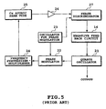
- Fig. 5 is a diagram showing the configuration of a conventional Cs atomic oscillator.
- reference numeral 21 indicates a quartz oscillator
- 22 is a phase modulator for the phase sensitive detection
- 23 is an oscillator for the phase modulator
- 24 is a frequency synthesizer/multiplier
- 25 is a Cs atomic beam tube
- 26 is an electrical amplifier
- 27 is a phase discriminator for the phase sensitive detection of deviations from the resonance frequency of the Cs atom
- 16 is a negative feedback circuit.
- the oscillator 21, which is the basis of the atomic oscillator incorporates a quartz oscillator and its oscillation frequency is typically 5 MHz. Its output signal is coupled into the phase modulator 22 to be phase modulated, and further multiplied by the frequency synthesizer/multiplier 24 up to a resonance frequency (depending on the atom employed) at several tens of GHz.
- the Cs atomic beam tube 25 consists of a Cs beam stream enclosed in a microwave resonant cavity, where the output signal (microwave) of the frequency synthesizer/multiplier 24 is coupled to the tube 25 to undergo resonance.
- a resonance line called a Ramsey resonance (fringe) is used.
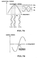
- the Ramsey resonance is a phenomenon in which, when the Cs beam interacts twice with the microwave at different positions, a resonance line with a very narrow band can be obtained at a frequency ⁇ o which is the center frequency of a Cs atom. This situation is shown in Fig. 6.
- a microwave with a phase modulation or a frequency modulation having a rate of fm is applied to the Cs tube and the frequency deviation from the central frequency ⁇ o (the Cs Ramsey resonance) is phase-discriminated.
- the rate of the frequency modulation is a few 100 Hz.
- Fig. 7A and 7B This state is shown in Fig. 7A, the microwave frequency is plotted on the horizontal axis, showing output signals with positive and negative phases, corresponding to below and above the central frequency ⁇ o . That is, the deviation from the resonance line is converted into an intensity signal, and the output signal of the atomic beam tube 25 is converted into a low frequency electrical signal which is intensity modulated at fm.
- the high frequency jitter characteristic of the repetition frequency of the harmonically and regeneratively mode-locked laser pulse oscillator was much better than the stability of the synthesizer.
- Such a highly stable oscillation circuit utilizing this scheme has not yet been proposed.
- the long-term stability (low-frequency drift) of this laser is limited by the stability of the synthesizer, which is still insufficient.
- the atomic oscillator has an excellent low-drift characteristic, there is no effective way of further suppressing of the high frequency jitter characteristics.
- the present invention incorporates an atomic frequency standard laser pulse oscillator in which the repetition frequency of a harmonically and regeneratively mode-locked laser pulse oscillator, with very little jitter at high frequency, is locked directly to the resonance frequency of various atoms.
- a self-oscillatory regeneratively mode-locked laser pulse oscillator in which the clock signal of an integral multiple of the longitudinal mode of a laser cavity is extracted and applied to an optical modulator installed in a laser cavity.
- the oscillator comprises a frequency difference detection device for detecting the frequency difference between a clock signal frequency (repetition frequency of optical pulse) and a predetermined atomic resonance frequency, a cavity length tuning device for changing the length of the laser cavity so that the clock signal frequency (repetition frequency of optical pulse) and the predetermined atomic resonance frequency coincide, and a device for negatively feeding back an error signal output from the frequency difference detection device to the cavity length tuning device to generate an ultra-short optical pulse train (optical output) of a repetition frequency stabilized at the predetermined atomic resonance frequency and a clock signal (microwave output).
- an ultra-stable microwave output can be obtained with less jitter than the prior art atomic oscillator.
- an ultra-short optical pulse train can be generated with a repetition frequency stabilized to the same level as a time standard.
- an ultra-stable microwave output (clock signal) can be obtained with less jitter than the prior art atomic oscillator, and an ultra-short optical pulse train can be generated with a repetition frequency stabilized at the same level as a time standard.
- Such an ultra-stable signal source can be utilized in, for example, a time standard, the precision measurement of crustal or tidal movement, the synchronization of communication networks, the high precision phase adjustment of a phase array antenna of a radio telescope, the generation of an ultra-high frequency in the THz region by using a beat signal within the laser longitudinal modes, and as a clock signal source for space communication. It is also possible to create a new frequency chain from a microwave to an optical wave. Further, since a light source with an ultra-stable repetition frequency can be obtained, it can be utilized in the light source of an ultra-high speed optical communication system and for other types of ultra-high speed optical signal processing.
- Fig. 1 is a diagram showing an example of the atomic frequency standard laser pulse oscillator according to the present invention.
- a rare-earth ion doped optical fiber 1 a pumping optical source 2, an optical coupler 3, an optical beam splitter 4, an optical isolator 5, an optical modulator 6, an optical filter 7, an optical beam splitter 8, a clock extraction circuit 9, a phase shifter 10, and a microwave electrical amplifier 11 are the same in construction as the prior art self-oscillatory regeneratively mode-locked laser pulse oscillator shown in Figs. 3 and 4.
- a piezoelectric transducer (PZT) 18 of the same construction as that shown in Fig. 4 is installed as a cavity length tuning device for varying the cavity length.
- the present embodiment is characterized in that a regeneratively mode-locked laser pulse oscillator including the cavity length tuning device is used in place of the quartz oscillator 21 of the atomic oscillator shown in Fig. 5. That is, a clock signal output from the clock extraction circuit 9 is coupled into a microwave phase modulator 22a, and an error signal output from the phase discriminator 27 is fed back to the piezoelectric transducer (PZT) 18 through the negative feedback circuit 16 and the electrical amplifier 17.
- the oscillator for the phase modulator 23, the Cs atomic beam tube 25, the electrical amplifier 26, the phase discriminator 27, and the negative feedback circuit 16 are the same in construction as those in the atomic oscillator shown in Fig. 5.
- a clock signal (output of clock extraction circuit 9) from the self-oscillatory regeneratively mode-locked laser pulse oscillator is coupled into the microwave phase modulator 22a and low frequency modulated by the oscillator for the phase modulator 23 for phase sensitive detection.
- the present embodiment does not require such a multiplication device since the clock signal frequency (repetition frequency of optical pulse) can be directly tuned to the atomic resonance frequency.
- the output signal of the microwave phase modulator 22a is input into the Cs atomic beam tube 25, an output signal obtained by interaction with the Cs Ramsey resonance line is amplified by the electrical amplifier 26, and coupled to the phase discriminator 27.
- the phase discriminator 27 a frequency deviation between the Cs Ramsey resonance frequency and the clock signal frequency (repetition frequency) of the regeneratively mode-locked laser pulse oscillator is phase-sensitively detected, and output as an error signal.
- This error signal is fed back to the piezoelectric transducer (PZT) 18 through the negative feedback circuit 16 and the electrical amplifier 17 to change the cavity length of the harmonically and regeneratively mode-locked laser pulse oscillator. With this operation, the repetition frequency of the harmonically and regeneratively mode-locked laser pulse oscillator can be exactly locked to the Cs Ramsey resonance frequency 9.192 GHz.
- This optical pulse can be demultiplexed (DEMUX) to generate a very high-precision one second interval ultra-short optical pulse train.
- This one second optical pulse can be utilized to provide the time to a community through an optical network.
- Such an optical demultiplexing circuit can be achieved using, for example, an optical Kerr switch, a nonlinear loop mirror (NOLM), a four wave mixing switch, and a cross phase modulation switch.
- the clock signal output from the clock extraction circuit 9 becomes a microwave electrical output.
- the frequency division of this microwave output is no difficulty since a frequency division circuit in the 10 to 40 GHZ region is already used in practical applications.
- a frequency dividing circuit 28 is used, an ultra-stable fundamental frequency output (one second clock) with much less jitter than the prior art atomic oscillator can be extracted. This is due to the superior low-jitter characteristic in the high Fourier frequency region of the regeneratively mode-locked laser pulse oscillator substituting for the quartz oscillator 21.
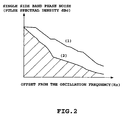
- Fig. 2 is a diagram showing an example of a comparison of the fluctuation of the oscillation frequency of the prior art atomic oscillator with that of the atomic frequency standard laser pulse oscillator according to the present invention.
- the horizontal axis is an offset frequency from the oscillation frequency itself, and the vertical axis is the measured power spectral density (SSB phase noise).
- (1) shows the fluctuation in the prior art atomic oscillator and (2) shows the fluctuation in the atomic frequency standard laser oscillator according to the present invention.
- the fluctuation in the frequency components is greater in the prior art type.
- This fluctuation is noise components caused by the quartz oscillator, showing that the noise can be substantially reduced by using a regeneratively mode-locked laser pulse oscillator.
- the integrated value of the hatched part indicates the jitter of the oscillator, and it is advantageous that this value is smaller.
- rubidium Rb (6.834 GHz), hydrogen H (1.420 GHz), thallium T1 (21.310 GHz), ammonia NH 3 (22.834GHz) or the like differing in resonance frequency can also be similarly utilized.
- erbium Er neodymium Nd, thulium Tm and the like can be used as the rare earth element of the rare-earth ion doped optical fiber 1 forming the regeneratively mode-locked laser pulse oscillator.
- a solid laser such as Ti- sapphire, or a semiconductor laser such as GaAs or InGaAsP can be used in the regeneratively mode-locked type.
- the oscillator provides the means (27) for detecting the frequency difference between the clock signal frequency and a predetermined atomic resonance frequency and outputting it as an error signal, a cavity length tuning device for varying the length of a laser cavity so that the clock signal frequency and the predetermined resonance frequency coincide, and a device (16) for negatively feeding back the error signal output from the frequency difference detection device (27) to the cavity length tuning device (18).
- This allows the generation of an optical pulse train (optical output) and a clock signal (microwave output) of a repetition frequency stabilized to the predetermined atomic resonance frequency.
Landscapes
- Physics & Mathematics (AREA)
- Electromagnetism (AREA)
- Engineering & Computer Science (AREA)
- Plasma & Fusion (AREA)
- Optics & Photonics (AREA)
- General Physics & Mathematics (AREA)
- Lasers (AREA)
- Stabilization Of Oscillater, Synchronisation, Frequency Synthesizers (AREA)
Claims (8)
- Oscillateur laser à impulsions laser pour un standard de fréquence atomique, comportant un oscillateur à impulsions laser à blocage de mode de manière régénérative et à auto oscillation, pour produire un train d'impulsions optiques en extrayant un signal d'horloge ayant un multiple entier du mode longitudinal de sa cavité laser et en appliquant le signal d'horloge à un modulateur (6) optique installé dans la cavité laser, comportant en outre un tube (25) de faisceau atomique produisant un signal d'oscillation ayant une fréquence de résonance atomique déterminée à l'avance ;
des moyens (27) de détection de différence destinés à détecter une différence de fréquence entre la fréquence du signal d'horloge et la fréquence de résonance atomique déterminée à l'avance ;
des moyens (18) d'accord de longueur de cavité destinés à modifier la longueur de cavité de la cavité laser de sorte que la fréquence du signal d'horloge et la fréquence de résonance atomique déterminée à l'avance coïncident ;
des moyens (16) destinés à fournir de manière négative en rétroaction une sortie de signal d'erreur des moyens de détection des différence de fréquences aux moyens d'accord de longueur de cavité ; et
la production d'un train d'impulsions optiques et d'un signal d'horloge d'une fréquence de répétition stabilisée à la fréquence de résonance atomique déterminée à l'avance. - Oscillateur laser à impulsions pour un standard de fréquence atomique suivant la revendication 1, caractérisé en ce que la fréquence de résonance atomique déterminée à l'avance est la fréquence de résonance Ramsey de 9,192 GHz du césium.
- Oscillateur laser à impulsions pour un standard de fréquence atomique suivant la revendication 1, caractérisé en ce que la fréquence de résonance atomique déterminée à l'avance est la fréquence de résonance de 6,834 GHz du rubidium.
- Oscillateur laser à impulsions pour un standard de fréquence atomique suivant la revendication 1, caractérisé en ce que la fréquence de résonance atomique déterminée à l'avance est la fréquence de résonance de 1,420 GHz de l'hydrogène.
- Oscillateur laser à impulsions pour un standard de fréquence atomique suivant la revendication 1, caractérisé en ce que la fréquence de résonance atomique déterminée à l'avance est la fréquence de résonance de 21, 310 GHz du thallium.
- Oscillateur laser à impulsions pour un standard de fréquence atomique suivant la revendication 1, caractérisé en ce que la fréquence de résonance atomique déterminée à l'avance est la fréquence de résonance de 22, 834 GHz du gaz d'ammoniac.
- Oscillateur laser à impulsions pour un standard de fréquence atomique, suivant la revendication 1, caractérisé par le fait de comporter un circuit de démutiplexage optique, destiné à démultiplexer le train d'impulsions optiques stabilisé à la fréquence de résonance atomique déterminée à l'avance et à émettre en sortie un trains d'impulsions optiques à un standard de temps donné.
- Oscillateur laser à impulsions pour un standard de fréquence atomique suivant la revendication 1, caractérisé par le fait de comporter un circuit de division de fréquence, destiné à diviser le signal d'horloge stabilisé à la fréquence de résonance atomique déterminée à l'avance et à émettre en sortie un signal standard à fréquence fixé à un standard de temps donné.
Applications Claiming Priority (2)
| Application Number | Priority Date | Filing Date | Title |
|---|---|---|---|
| JP35883198A JP3443534B2 (ja) | 1998-12-17 | 1998-12-17 | 原子周波数標準レーザパルス発振器 |
| JP35883198 | 1998-12-17 |
Publications (3)
| Publication Number | Publication Date |
|---|---|
| EP1014518A2 EP1014518A2 (fr) | 2000-06-28 |
| EP1014518A3 EP1014518A3 (fr) | 2001-09-05 |
| EP1014518B1 true EP1014518B1 (fr) | 2004-09-22 |
Family
ID=18461339
Family Applications (1)
| Application Number | Title | Priority Date | Filing Date |
|---|---|---|---|
| EP99125101A Expired - Lifetime EP1014518B1 (fr) | 1998-12-17 | 1999-12-16 | Oscillateur laser à impulsions pour un standard de fréquence atomique |
Country Status (4)
| Country | Link |
|---|---|
| US (1) | US6333942B1 (fr) |
| EP (1) | EP1014518B1 (fr) |
| JP (1) | JP3443534B2 (fr) |
| DE (1) | DE69920386T2 (fr) |
Cited By (1)
| Publication number | Priority date | Publication date | Assignee | Title |
|---|---|---|---|---|
| CN110554597A (zh) * | 2019-08-25 | 2019-12-10 | 中国科学院国家授时中心 | 基于Vondark-Cepek滤波的氢铯时间尺度融合方法 |
Families Citing this family (31)
| Publication number | Priority date | Publication date | Assignee | Title |
|---|---|---|---|---|
| JP2000332348A (ja) * | 1999-05-24 | 2000-11-30 | Oki Electric Ind Co Ltd | モード同期半導体レーザ |
| WO2001076026A1 (fr) * | 2000-03-30 | 2001-10-11 | National Institute Of Standards And Technology ('nist') | Procede et systeme de laser pulse a modes synchronises |
| DE10044404C2 (de) * | 2000-09-08 | 2002-08-14 | Max Planck Gesellschaft | Verfahren und Vorrichtung zur Erzeugung von stabilisierten ultrakurzen Laser-Lichtpulsen |
| US6831522B2 (en) * | 2001-07-09 | 2004-12-14 | The United States Of America As Represented By The Secretary Of Commerce | Method of minimizing the short-term frequency instability of laser-pumped atomic clocks |
| JP2003242727A (ja) * | 2002-02-12 | 2003-08-29 | Nippon Sogo Seisaku Kk | デジタルオーディオ用基準発振器を採用した記録再生方法 |
| JP2004030401A (ja) * | 2002-06-27 | 2004-01-29 | Nippon Sogo Seisaku Kk | 機械制御用基準発振器に原子周波数標準器を採用した超高安定な回転系の定速制御および位置決め制御方法 |
| JP4471572B2 (ja) * | 2003-01-31 | 2010-06-02 | 独立行政法人科学技術振興機構 | 光伝送方法 |
| US7492795B1 (en) | 2004-01-06 | 2009-02-17 | University Of Central Florida Research Foundation, Inc. | Ultralow noise mode-locked laser and RF sinewave source |
| EP1746398A1 (fr) * | 2004-05-14 | 2007-01-24 | Japan Science and Technology Agency | Méthode de détection force/masse de haute sensibilité et dispositif utilisant un circuit de synchronisation de phase |
| US7494598B2 (en) * | 2005-11-22 | 2009-02-24 | Honeywell International Inc. | Miniature optically transparent window |
| JP4478800B2 (ja) * | 2006-05-15 | 2010-06-09 | 独立行政法人産業技術総合研究所 | クロック伝送装置 |
| JP4951762B2 (ja) * | 2007-03-29 | 2012-06-13 | 国立大学法人東北大学 | パルスレーザ光源 |
| JP4953943B2 (ja) * | 2007-07-02 | 2012-06-13 | 株式会社アドバンテスト | モードロックレーザ装置 |
| JP2009140581A (ja) * | 2007-12-07 | 2009-06-25 | Time Technology Kk | デジタル・オーディオ用記録再生装置 |
| RU2369958C1 (ru) * | 2008-04-07 | 2009-10-10 | Открытое акционерное общество "Российский институт радионавигации и времени" | Квантовый стандарт частоты на газовой ячейке с импульсной лазерной накачкой |
| RU2369959C1 (ru) * | 2008-04-07 | 2009-10-10 | Открытое акционерное общество "Российский институт радионавигации и времени" | Квантовый стандарт частоты на газовой ячейке с импульсной лазерной накачкой |
| CN101604815B (zh) * | 2009-06-26 | 2011-02-09 | 哈尔滨工业大学(威海) | 一种控制脉冲激光建立时间的激光稳频方法 |
| GB2475331A (en) * | 2009-11-17 | 2011-05-18 | Rad Data Comm Ltd | Reference frequency source |
| JP5608921B2 (ja) * | 2010-08-05 | 2014-10-22 | 国立大学法人東北大学 | 半導体光位相変調器を用いた高繰り返しフェムト秒ファイバレーザ |
| GB201200219D0 (en) * | 2012-01-09 | 2012-02-22 | Calder Martin | A clock signal generator for a digital circuit |
| CN103326221B (zh) * | 2013-06-25 | 2015-07-01 | 上海朗研光电科技有限公司 | 利用环型光纤有源腔共振增强倍频光效率的方法 |
| CN103633537B (zh) * | 2013-11-13 | 2016-09-14 | 中国科学院物理研究所 | 一种载波包络相移频率可控的低噪声光纤激光频率梳装置 |
| CN103762496B (zh) * | 2014-01-06 | 2016-05-25 | 中国科学院物理研究所 | 基于全固态飞秒激光器的天文光学频率梳装置 |
| CN107302178B (zh) * | 2017-06-26 | 2019-11-19 | 天津理工大学 | 基于二维材料光电器件的再生锁模光纤激光器 |
| CN108508733B (zh) * | 2018-04-13 | 2020-02-21 | 北京大学 | 基于窄脉冲调制展宽的宽谱激光抽运铷原子微波钟 |
| WO2020087423A1 (fr) | 2018-10-31 | 2020-05-07 | 浙江大学 | Système de résonance d'hyperfréquences à transport optique bidirectionnel basé sur une structure de circulateur et procédé de détection de vitesse angulaire par ledit système |
| CN112332198B (zh) * | 2020-11-02 | 2022-04-22 | 中国科学院半导体研究所 | 光电振荡器 |
| CN113050404B (zh) * | 2021-03-23 | 2022-07-19 | 深港产学研基地(北京大学香港科技大学深圳研修院) | 基于脉冲调制宽谱多频激光的铷原子光钟及实现方法 |
| CN113655700B (zh) * | 2021-08-19 | 2022-09-13 | 中国计量科学研究院 | 应用于冷原子喷泉钟的小型化主激光光路装置及调整方法 |
| CN114578547B (zh) * | 2022-03-23 | 2024-04-26 | 北京无线电计量测试研究所 | 一种原子束光钟光束指向控制方法及装置 |
| CN116599619B (zh) * | 2023-07-17 | 2023-09-22 | 成都通航科技有限公司 | 一种高精度远距离光纤同步系统 |
Family Cites Families (12)
| Publication number | Priority date | Publication date | Assignee | Title |
|---|---|---|---|---|
| US4635266A (en) | 1984-12-11 | 1987-01-06 | The United States Of America As Represented By The Secretary Of The Air Force | Active dispersion control for a Doppler broadened laser |
| US4661782A (en) * | 1985-11-25 | 1987-04-28 | Ball Corporation | Integrated microwave cavity resonator and magnetic shield for an atomic frequency standard |
| JPH0761013B2 (ja) * | 1988-07-19 | 1995-06-28 | 富士通株式会社 | セシウム原子発振器 |
| JPH02138235A (ja) | 1988-07-20 | 1990-05-28 | Takeda Chem Ind Ltd | 光学活性化合物、同中間体、該化合物を含有する液晶組成物及び該液晶組成物を用いた液晶光変調装置 |
| FR2644315B1 (fr) * | 1989-03-13 | 1991-05-24 | Oscilloquartz Sa | Module d'interaction micro-onde, notamment pour un resonateur a jet atomique ou moleculaire |
| JP2788807B2 (ja) | 1991-10-16 | 1998-08-20 | 日本電気株式会社 | ルビジウム原子発振器 |
| JP3434869B2 (ja) * | 1994-02-07 | 2003-08-11 | 株式会社日立製作所 | 光再生中継器および光伝送装置 |
| JP3191843B2 (ja) | 1994-06-29 | 2001-07-23 | 日本電信電話株式会社 | レーザパルス発振器 |
| JP2856108B2 (ja) * | 1995-05-31 | 1999-02-10 | 日本電気株式会社 | 周波数逸脱検出回路 |
| JP2735039B2 (ja) | 1995-06-09 | 1998-04-02 | 日本電気株式会社 | 光パルス発生方法および装置 |
| JPH1074999A (ja) | 1996-09-02 | 1998-03-17 | Nippon Telegr & Teleph Corp <Ntt> | レーザパルス発振器 |
| US6204944B1 (en) * | 1997-07-18 | 2001-03-20 | Nippon Telegraph And Telephone Corporation | All-optical time-division demultiplexing circuit and all-optical TDM-WDM conversion circuit |
-
1998
- 1998-12-17 JP JP35883198A patent/JP3443534B2/ja not_active Expired - Fee Related
-
1999
- 1999-12-14 US US09/461,181 patent/US6333942B1/en not_active Expired - Lifetime
- 1999-12-16 EP EP99125101A patent/EP1014518B1/fr not_active Expired - Lifetime
- 1999-12-16 DE DE69920386T patent/DE69920386T2/de not_active Expired - Lifetime
Cited By (1)
| Publication number | Priority date | Publication date | Assignee | Title |
|---|---|---|---|---|
| CN110554597A (zh) * | 2019-08-25 | 2019-12-10 | 中国科学院国家授时中心 | 基于Vondark-Cepek滤波的氢铯时间尺度融合方法 |
Also Published As
| Publication number | Publication date |
|---|---|
| US6333942B1 (en) | 2001-12-25 |
| EP1014518A3 (fr) | 2001-09-05 |
| JP3443534B2 (ja) | 2003-09-02 |
| DE69920386T2 (de) | 2005-10-06 |
| EP1014518A2 (fr) | 2000-06-28 |
| JP2000183430A (ja) | 2000-06-30 |
| DE69920386D1 (de) | 2004-10-28 |
Similar Documents
| Publication | Publication Date | Title |
|---|---|---|
| US6333942B1 (en) | Atomic frequency standard laser pulse oscillator | |
| Nakazawa et al. | Ideal phase-locked-loop (PLL) operation of a 10 GHz erbium-doped fibre laser using regenerative modelocking as an optical voltage controlled oscillator | |
| KR101633466B1 (ko) | 광빗에서 직접적으로 추출된 광모드를 이용하여 펨토초레이저의 광빗이 갖는 전체적 주파수의 안정화를 구현하는 장치 및 방법 | |
| US20180115136A1 (en) | Ultra-low noise mode-locked laser, methods, and applications | |
| CN112213938B (zh) | 一种光频原子钟 | |
| US5926492A (en) | Laser pulse oscillator | |
| CN110867720B (zh) | 一种小型化低成本大频率调谐范围稳频激光器系统及方法 | |
| Bluestone et al. | An ultra-low phase-noise 20-GHz PLL utilizing an optoelectronic voltage-controlled oscillator | |
| JP2016099630A (ja) | 細かい光周波数コム及び粗い光周波数コムを用いた光シンセサイザの調整 | |
| Bagayev et al. | A femtosecond self-mode-locked Ti: sapphire laser with high stability of pulse-repetition frequency and its applications | |
| JP3772650B2 (ja) | モード同期半導体レーザの駆動方法及び装置 | |
| US5751193A (en) | Rubidium atomic oscillator with laser diode wavelength adjustment | |
| JP4072053B2 (ja) | 周波数シンセサイザ | |
| CN120934509A (zh) | 一种宽带可调谐低相噪光生微波信号源及装置 | |
| CN116937294B (zh) | 一种微波产生装置及产生方法 | |
| US7583711B2 (en) | Apparatus and method for stabilizing the frequency of lasers | |
| JP2000244044A (ja) | ファブリペローフィルターを用いた再生モード同期レーザ | |
| RU2148881C1 (ru) | Водородный стандарт частоты | |
| EP4664192A1 (fr) | Systèmes de transfert de stabilité d'une source optique à une source rf | |
| Egbert et al. | Attosecond-timing millimeter waves via Kerr optical frequency division | |
| Zhang et al. | Research on the Frequency Stability of Optoelectronic Oscillator | |
| Rolland et al. | Attosecond timing jitter in millimeter waves via Kerr optical frequency division | |
| Pennanech et al. | Direct generation of Cs-based atomic clock RF interrogation signal by an optoelectronic oscillator | |
| JPH06152406A (ja) | 位相同期型ルビジウム原子発振器 | |
| JPS63957B2 (fr) |
Legal Events
| Date | Code | Title | Description |
|---|---|---|---|
| PUAI | Public reference made under article 153(3) epc to a published international application that has entered the european phase |
Free format text: ORIGINAL CODE: 0009012 |
|
| AK | Designated contracting states |
Kind code of ref document: A2 Designated state(s): AT BE CH CY DE DK ES FI FR GB GR IE IT LI LU MC NL PT SE |
|
| AX | Request for extension of the european patent |
Free format text: AL;LT;LV;MK;RO;SI |
|
| PUAL | Search report despatched |
Free format text: ORIGINAL CODE: 0009013 |
|
| AK | Designated contracting states |
Kind code of ref document: A3 Designated state(s): AT BE CH CY DE DK ES FI FR GB GR IE IT LI LU MC NL PT SE |
|
| AX | Request for extension of the european patent |
Free format text: AL;LT;LV;MK;RO;SI |
|
| RIC1 | Information provided on ipc code assigned before grant |
Free format text: 7H 01S 3/139 A, 7H 01S 3/098 B, 7H 01S 3/067 B, 7G 04F 5/14 B |
|
| 17P | Request for examination filed |
Effective date: 20020304 |
|
| AKX | Designation fees paid |
Free format text: DE FR GB IT |
|
| GRAP | Despatch of communication of intention to grant a patent |
Free format text: ORIGINAL CODE: EPIDOSNIGR1 |
|
| RIN1 | Information on inventor provided before grant (corrected) |
Inventor name: YOSHIDA, EIJI,C/O NIPPON TELEGRAPH AND Inventor name: NAKAZAWA, MASATAKA,C/O NIPPON TELEGRAPH AND |
|
| GRAS | Grant fee paid |
Free format text: ORIGINAL CODE: EPIDOSNIGR3 |
|
| GRAA | (expected) grant |
Free format text: ORIGINAL CODE: 0009210 |
|
| AK | Designated contracting states |
Kind code of ref document: B1 Designated state(s): DE FR GB IT |
|
| REG | Reference to a national code |
Ref country code: GB Ref legal event code: FG4D |
|
| REF | Corresponds to: |
Ref document number: 69920386 Country of ref document: DE Date of ref document: 20041028 Kind code of ref document: P |
|
| ET | Fr: translation filed | ||
| PLBE | No opposition filed within time limit |
Free format text: ORIGINAL CODE: 0009261 |
|
| STAA | Information on the status of an ep patent application or granted ep patent |
Free format text: STATUS: NO OPPOSITION FILED WITHIN TIME LIMIT |
|
| 26N | No opposition filed |
Effective date: 20050623 |
|
| PGFP | Annual fee paid to national office [announced via postgrant information from national office to epo] |
Ref country code: GB Payment date: 20121218 Year of fee payment: 14 Ref country code: IT Payment date: 20121221 Year of fee payment: 14 |
|
| PGFP | Annual fee paid to national office [announced via postgrant information from national office to epo] |
Ref country code: DE Payment date: 20121227 Year of fee payment: 14 Ref country code: FR Payment date: 20130123 Year of fee payment: 14 |
|
| REG | Reference to a national code |
Ref country code: DE Ref legal event code: R119 Ref document number: 69920386 Country of ref document: DE |
|
| GBPC | Gb: european patent ceased through non-payment of renewal fee |
Effective date: 20131216 |
|
| REG | Reference to a national code |
Ref country code: FR Ref legal event code: ST Effective date: 20140829 |
|
| REG | Reference to a national code |
Ref country code: DE Ref legal event code: R119 Ref document number: 69920386 Country of ref document: DE Effective date: 20140701 |
|
| PG25 | Lapsed in a contracting state [announced via postgrant information from national office to epo] |
Ref country code: DE Free format text: LAPSE BECAUSE OF NON-PAYMENT OF DUE FEES Effective date: 20140701 |
|
| PG25 | Lapsed in a contracting state [announced via postgrant information from national office to epo] |
Ref country code: FR Free format text: LAPSE BECAUSE OF NON-PAYMENT OF DUE FEES Effective date: 20131231 Ref country code: GB Free format text: LAPSE BECAUSE OF NON-PAYMENT OF DUE FEES Effective date: 20131216 |
|
| PG25 | Lapsed in a contracting state [announced via postgrant information from national office to epo] |
Ref country code: IT Free format text: LAPSE BECAUSE OF NON-PAYMENT OF DUE FEES Effective date: 20131231 |
|
| PG25 | Lapsed in a contracting state [announced via postgrant information from national office to epo] |
Ref country code: IT Free format text: LAPSE BECAUSE OF NON-PAYMENT OF DUE FEES Effective date: 20131216 |