EP1014542A2 - Moteur comportant des aimants fendus insérés dans le rotor - Google Patents
Moteur comportant des aimants fendus insérés dans le rotor Download PDFInfo
- Publication number
- EP1014542A2 EP1014542A2 EP99125812A EP99125812A EP1014542A2 EP 1014542 A2 EP1014542 A2 EP 1014542A2 EP 99125812 A EP99125812 A EP 99125812A EP 99125812 A EP99125812 A EP 99125812A EP 1014542 A2 EP1014542 A2 EP 1014542A2
- Authority
- EP
- European Patent Office
- Prior art keywords
- magnet
- motor
- rotor
- stator
- permanent magnets
- Prior art date
- Legal status (The legal status is an assumption and is not a legal conclusion. Google has not performed a legal analysis and makes no representation as to the accuracy of the status listed.)
- Granted
Links
Images




Classifications
-
- H—ELECTRICITY
- H02—GENERATION; CONVERSION OR DISTRIBUTION OF ELECTRIC POWER
- H02K—DYNAMO-ELECTRIC MACHINES
- H02K1/00—Details of the magnetic circuit
- H02K1/06—Details of the magnetic circuit characterised by the shape, form or construction
- H02K1/22—Rotating parts of the magnetic circuit
- H02K1/27—Rotor cores with permanent magnets
- H02K1/2706—Inner rotors
- H02K1/272—Inner rotors the magnetisation axis of the magnets being perpendicular to the rotor axis
- H02K1/274—Inner rotors the magnetisation axis of the magnets being perpendicular to the rotor axis the rotor consisting of two or more circumferentially positioned magnets
- H02K1/2753—Inner rotors the magnetisation axis of the magnets being perpendicular to the rotor axis the rotor consisting of two or more circumferentially positioned magnets the rotor consisting of magnets or groups of magnets arranged with alternating polarity
- H02K1/276—Magnets embedded in the magnetic core, e.g. interior permanent magnets [IPM]
- H02K1/2766—Magnets embedded in the magnetic core, e.g. interior permanent magnets [IPM] having a flux concentration effect
-
- B—PERFORMING OPERATIONS; TRANSPORTING
- B60—VEHICLES IN GENERAL
- B60L—PROPULSION OF ELECTRICALLY-PROPELLED VEHICLES; SUPPLYING ELECTRIC POWER FOR AUXILIARY EQUIPMENT OF ELECTRICALLY-PROPELLED VEHICLES; ELECTRODYNAMIC BRAKE SYSTEMS FOR VEHICLES IN GENERAL; MAGNETIC SUSPENSION OR LEVITATION FOR VEHICLES; MONITORING OPERATING VARIABLES OF ELECTRICALLY-PROPELLED VEHICLES; ELECTRIC SAFETY DEVICES FOR ELECTRICALLY-PROPELLED VEHICLES
- B60L15/00—Methods, circuits, or devices for controlling the traction-motor speed of electrically-propelled vehicles
- B60L15/20—Methods, circuits, or devices for controlling the traction-motor speed of electrically-propelled vehicles for control of the vehicle or its driving motor to achieve a desired performance, e.g. speed, torque, programmed variation of speed
-
- B—PERFORMING OPERATIONS; TRANSPORTING
- B60—VEHICLES IN GENERAL
- B60L—PROPULSION OF ELECTRICALLY-PROPELLED VEHICLES; SUPPLYING ELECTRIC POWER FOR AUXILIARY EQUIPMENT OF ELECTRICALLY-PROPELLED VEHICLES; ELECTRODYNAMIC BRAKE SYSTEMS FOR VEHICLES IN GENERAL; MAGNETIC SUSPENSION OR LEVITATION FOR VEHICLES; MONITORING OPERATING VARIABLES OF ELECTRICALLY-PROPELLED VEHICLES; ELECTRIC SAFETY DEVICES FOR ELECTRICALLY-PROPELLED VEHICLES
- B60L3/00—Electric devices on electrically-propelled vehicles for safety purposes; Monitoring operating variables, e.g. speed, deceleration or energy consumption
- B60L3/0023—Detecting, eliminating, remedying or compensating for drive train abnormalities, e.g. failures within the drive train
- B60L3/0061—Detecting, eliminating, remedying or compensating for drive train abnormalities, e.g. failures within the drive train relating to electrical machines
-
- B—PERFORMING OPERATIONS; TRANSPORTING
- B60—VEHICLES IN GENERAL
- B60L—PROPULSION OF ELECTRICALLY-PROPELLED VEHICLES; SUPPLYING ELECTRIC POWER FOR AUXILIARY EQUIPMENT OF ELECTRICALLY-PROPELLED VEHICLES; ELECTRODYNAMIC BRAKE SYSTEMS FOR VEHICLES IN GENERAL; MAGNETIC SUSPENSION OR LEVITATION FOR VEHICLES; MONITORING OPERATING VARIABLES OF ELECTRICALLY-PROPELLED VEHICLES; ELECTRIC SAFETY DEVICES FOR ELECTRICALLY-PROPELLED VEHICLES
- B60L50/00—Electric propulsion with power supplied within the vehicle
- B60L50/50—Electric propulsion with power supplied within the vehicle using propulsion power supplied by batteries or fuel cells
- B60L50/52—Electric propulsion with power supplied within the vehicle using propulsion power supplied by batteries or fuel cells characterised by DC-motors
-
- B—PERFORMING OPERATIONS; TRANSPORTING
- B60—VEHICLES IN GENERAL
- B60L—PROPULSION OF ELECTRICALLY-PROPELLED VEHICLES; SUPPLYING ELECTRIC POWER FOR AUXILIARY EQUIPMENT OF ELECTRICALLY-PROPELLED VEHICLES; ELECTRODYNAMIC BRAKE SYSTEMS FOR VEHICLES IN GENERAL; MAGNETIC SUSPENSION OR LEVITATION FOR VEHICLES; MONITORING OPERATING VARIABLES OF ELECTRICALLY-PROPELLED VEHICLES; ELECTRIC SAFETY DEVICES FOR ELECTRICALLY-PROPELLED VEHICLES
- B60L50/00—Electric propulsion with power supplied within the vehicle
- B60L50/50—Electric propulsion with power supplied within the vehicle using propulsion power supplied by batteries or fuel cells
- B60L50/60—Electric propulsion with power supplied within the vehicle using propulsion power supplied by batteries or fuel cells using power supplied by batteries
- B60L50/66—Arrangements of batteries
-
- H—ELECTRICITY
- H02—GENERATION; CONVERSION OR DISTRIBUTION OF ELECTRIC POWER
- H02K—DYNAMO-ELECTRIC MACHINES
- H02K1/00—Details of the magnetic circuit
- H02K1/06—Details of the magnetic circuit characterised by the shape, form or construction
- H02K1/22—Rotating parts of the magnetic circuit
- H02K1/27—Rotor cores with permanent magnets
- H02K1/2706—Inner rotors
- H02K1/272—Inner rotors the magnetisation axis of the magnets being perpendicular to the rotor axis
- H02K1/274—Inner rotors the magnetisation axis of the magnets being perpendicular to the rotor axis the rotor consisting of two or more circumferentially positioned magnets
- H02K1/2753—Inner rotors the magnetisation axis of the magnets being perpendicular to the rotor axis the rotor consisting of two or more circumferentially positioned magnets the rotor consisting of magnets or groups of magnets arranged with alternating polarity
- H02K1/276—Magnets embedded in the magnetic core, e.g. interior permanent magnets [IPM]
-
- H—ELECTRICITY
- H02—GENERATION; CONVERSION OR DISTRIBUTION OF ELECTRIC POWER
- H02K—DYNAMO-ELECTRIC MACHINES
- H02K21/00—Synchronous motors having permanent magnets; Synchronous generators having permanent magnets
- H02K21/12—Synchronous motors having permanent magnets; Synchronous generators having permanent magnets with stationary armatures and rotating magnets
- H02K21/14—Synchronous motors having permanent magnets; Synchronous generators having permanent magnets with stationary armatures and rotating magnets with magnets rotating within the armatures
- H02K21/16—Synchronous motors having permanent magnets; Synchronous generators having permanent magnets with stationary armatures and rotating magnets with magnets rotating within the armatures having annular armature cores with salient poles
-
- H—ELECTRICITY
- H02—GENERATION; CONVERSION OR DISTRIBUTION OF ELECTRIC POWER
- H02K—DYNAMO-ELECTRIC MACHINES
- H02K7/00—Arrangements for handling mechanical energy structurally associated with dynamo-electric machines, e.g. structural association with mechanical driving motors or auxiliary dynamo-electric machines
- H02K7/006—Structural association of a motor or generator with the drive train of a motor vehicle
-
- B—PERFORMING OPERATIONS; TRANSPORTING
- B60—VEHICLES IN GENERAL
- B60L—PROPULSION OF ELECTRICALLY-PROPELLED VEHICLES; SUPPLYING ELECTRIC POWER FOR AUXILIARY EQUIPMENT OF ELECTRICALLY-PROPELLED VEHICLES; ELECTRODYNAMIC BRAKE SYSTEMS FOR VEHICLES IN GENERAL; MAGNETIC SUSPENSION OR LEVITATION FOR VEHICLES; MONITORING OPERATING VARIABLES OF ELECTRICALLY-PROPELLED VEHICLES; ELECTRIC SAFETY DEVICES FOR ELECTRICALLY-PROPELLED VEHICLES
- B60L2240/00—Control parameters of input or output; Target parameters
- B60L2240/10—Vehicle control parameters
- B60L2240/36—Temperature of vehicle components or parts
-
- B—PERFORMING OPERATIONS; TRANSPORTING
- B60—VEHICLES IN GENERAL
- B60L—PROPULSION OF ELECTRICALLY-PROPELLED VEHICLES; SUPPLYING ELECTRIC POWER FOR AUXILIARY EQUIPMENT OF ELECTRICALLY-PROPELLED VEHICLES; ELECTRODYNAMIC BRAKE SYSTEMS FOR VEHICLES IN GENERAL; MAGNETIC SUSPENSION OR LEVITATION FOR VEHICLES; MONITORING OPERATING VARIABLES OF ELECTRICALLY-PROPELLED VEHICLES; ELECTRIC SAFETY DEVICES FOR ELECTRICALLY-PROPELLED VEHICLES
- B60L2240/00—Control parameters of input or output; Target parameters
- B60L2240/40—Drive Train control parameters
- B60L2240/42—Drive Train control parameters related to electric machines
- B60L2240/423—Torque
-
- Y—GENERAL TAGGING OF NEW TECHNOLOGICAL DEVELOPMENTS; GENERAL TAGGING OF CROSS-SECTIONAL TECHNOLOGIES SPANNING OVER SEVERAL SECTIONS OF THE IPC; TECHNICAL SUBJECTS COVERED BY FORMER USPC CROSS-REFERENCE ART COLLECTIONS [XRACs] AND DIGESTS
- Y02—TECHNOLOGIES OR APPLICATIONS FOR MITIGATION OR ADAPTATION AGAINST CLIMATE CHANGE
- Y02T—CLIMATE CHANGE MITIGATION TECHNOLOGIES RELATED TO TRANSPORTATION
- Y02T10/00—Road transport of goods or passengers
- Y02T10/60—Other road transportation technologies with climate change mitigation effect
- Y02T10/64—Electric machine technologies in electromobility
-
- Y—GENERAL TAGGING OF NEW TECHNOLOGICAL DEVELOPMENTS; GENERAL TAGGING OF CROSS-SECTIONAL TECHNOLOGIES SPANNING OVER SEVERAL SECTIONS OF THE IPC; TECHNICAL SUBJECTS COVERED BY FORMER USPC CROSS-REFERENCE ART COLLECTIONS [XRACs] AND DIGESTS
- Y02—TECHNOLOGIES OR APPLICATIONS FOR MITIGATION OR ADAPTATION AGAINST CLIMATE CHANGE
- Y02T—CLIMATE CHANGE MITIGATION TECHNOLOGIES RELATED TO TRANSPORTATION
- Y02T10/00—Road transport of goods or passengers
- Y02T10/60—Other road transportation technologies with climate change mitigation effect
- Y02T10/70—Energy storage systems for electromobility, e.g. batteries
-
- Y—GENERAL TAGGING OF NEW TECHNOLOGICAL DEVELOPMENTS; GENERAL TAGGING OF CROSS-SECTIONAL TECHNOLOGIES SPANNING OVER SEVERAL SECTIONS OF THE IPC; TECHNICAL SUBJECTS COVERED BY FORMER USPC CROSS-REFERENCE ART COLLECTIONS [XRACs] AND DIGESTS
- Y02—TECHNOLOGIES OR APPLICATIONS FOR MITIGATION OR ADAPTATION AGAINST CLIMATE CHANGE
- Y02T—CLIMATE CHANGE MITIGATION TECHNOLOGIES RELATED TO TRANSPORTATION
- Y02T10/00—Road transport of goods or passengers
- Y02T10/60—Other road transportation technologies with climate change mitigation effect
- Y02T10/72—Electric energy management in electromobility
Definitions
- the present invention relates generally to a motor having a rotor with interior permanent magnets, more particularly it relates to a motor with interior split-permanent-magnets, thereby restrains eddy-current from occurring and prevents heat-demagnetization.
- Fig. 11 illustrates a rotor with interior permanent magnets of a conventional motor.
- the motor has rotor 310 in which permanent magnets 312 are embedded, and rotor 310 is disposed in a stator (not shown) with concentrated windings, so that the motor can driven by not only magnet torque but also reluctance torque.
- This rotor is hereinafter referred to as a "rotor with interior permanent magnets”.
- the distributed-winding stator is structured in the following way: A slot is formed between two stator-teeth, and a plurality of teeth thus form a plurality of slots. Windings striding over at least one slot are provided, and part of a winding of a phase exists between pitches of another phase winding.
- the concentrated-winding stator is structured by providing a winding of one phase to one stator tooth respectively.
- a motor has the concentrated winding stator, and yet, the permanent magnets are stuck onto an outer wall of the rotor, the changes in magnetic-flux-density is not so large that the heat-demagnetization due to the eddy-current-loss is negligible.
- the space between the magnet and the outer circumference of rotor core 314 forms a path for the magnetic-flux to flow.
- the density of magnetic-flux from the stator changes depending on the position of stator teeth with regard to the magnets, so that magnitude of changes in the magnetic-flux-density at the path is increased.
- eddy-current occurs in magnets 312 embedded in rotor 310, thereby heating the magnet to produce irreversible heat-demagnetization.
- the present invention addresses the problems discussed above and aims to provide a motor having a rotor with interior-permanent-magnets. This rotor produces the less eddy-current and can prevent the heat-demagnetization in the permanent magnets embedded in the rotor.
- the motor of the present invention comprises the following elements:
- the permanent magnets are split in respective sides facing the stator, and insulating sections are inserted into respective gaps between respective split magnets. This structure splits the magnets electrically thereby restraining the eddy-current from occurring and then suppressing the heat-demagnetization in the magnets embedded into the rotor.
- Fig. 1 is a cross section illustrating a motor, having a rotor with interior permanent magnets, in accordance with the first exemplary embodiment of the present invention
- Fig. 2 is a perspective view of the permanent magnets to be embedded into the rotor of the same embodiment.
- motor 10 includes rotor 14 with interior permanent magnets 12, and stator 15 facing to rotor 14 via annular space. Respective teeth 17 of stator 15 are wound by windings 18 in a concentrated manner, i.e. concentrated windings are provided to respective teeth.
- Rotor 14 comprises the following elements:
- Respective magnets 12 have a shape protruding toward the center of rotor core. As such, the magnets are embedded into the rotor so that rotor 4 can produce respective directions for magnetic flux to flow with ease and with difficulty. An inductance ratio in respective directions can be thus obtained, and it is called a salient pole rate.
- a rotor polarity is formed between magnet 12 and an outer wall of the rotor core to which magnets 12 face.
- the magnetic-flux from the permanent magnet flows with ease though the section covering the rotor polarity, and this flowing direction is called "d axis”.
- the magnetic-flux flows with difficulty through a section covering a boundary between two adjacent magnets, and this flowing direction is called "q axis”.
- Stator 15 is formed by linking twelve stator-blocks 19 to each other in an annular shape.
- Each stator block 19 comprises teeth 17 wound by winding 18 in the concentrated manner, and the blocks are welded to form a ring.
- windings provided to a first four teeth every three teeth out of 12 teeth are coupled with each other thereby forming phase "U”.
- the windings provided to the second four teeth on the right side of the respective first four teeth discussed above are coupled with each other thereby forming phase "V”.
- the windings provided to the third four teeth on the left side of the first four teeth are coupled with each other thereby forming phase "W”.
- Stator 15 thus forms three-phase with concentrated windings.
- This motor has the salient-pole-rate and controls the current-phases to be optimal by current thereby driving itself not only by the magnet torque but also by the reluctance torque.
- One of the features of the present invention is a method of embedding the permanent magnets into the rotor. Magnets 12 to be embedded into rotor 14 in the first exemplary embodiment are detailed hereinafter.
- each magnet 12 is split into two magnet pieces 13 in the axial direction of rotor 14. Each two magnet pieces 13 are embedded into one single hole provided to rotor 14, thereby forming each magnet 12.
- Epoxy resin of electrically insulating, used as a coating material, is applied to the overall surface of each magnet piece 13. If magnet pieces 13 are stacked-up, each piece is electrically insulated and they can form an independent circuit. A space between respective stacked-up magnet pieces 13 is not less than 0.03 mm corresponding to the thickness of coating material applied to the magnet pieces.
- Respective magnet pieces 13 are embedded adjacently with each other into the hole of the rotor core so that magnet 12 is split into two sections facing to stator 15. Respective magnet pieces 13 are arranged in the following way: Respective magnetic-fluxes generated from two magnet pieces embedded in one hole flow in the same direction with regard to the outer wall of the rotor to which these two magnet pieces face. Another pair of magnet pieces embedded into a hole adjacent to the hole discussed above generate the magnetic flux in the direction reversed to the direction of the magnetic flux discussed above. For instance, two magnetic pieces embedded into one hole face to the outer wall of the rotor with poles "N", then another pair of magnet pieces embedded into the hole adjacent to this hole should face to the outer wall with poles "S".
- the space between the two magnet pieces is not necessarily resin, and it can be any electrically-insulating-materials including air-gap.
- Magnet 12 is split by a plane facing toward stator 15, thereby reducing the eddy current produced in magnet 12.
- the plane extends from the rotor center toward the stator. This is because of the following reason:
- stator 15 receives greater changes in the density of magnetic-flux supplied from teeth 17.
- the maximum operable magnetic-flux-density B m expressed in the equation discussed previously thus grows greater.
- This change in the magnetic-flux-density produces the eddy current in each magnet 12.
- each magnet 12 embedded in rotor 14 is split into two magnet pieces 13, and epoxy resin ⁇ which is non-magnetic material ⁇ is put between these two pieces, thereby dividing magnet 12 not only physically but also electrically.
- the production of eddy current is restrained by narrowing the width "t" of plate interlinking with the magnetic flux in the equation discussed previously.
- Fig. 3 is a perspective view of permanent magnets to be embedded into a rotor of a motor in accordance with the second exemplary embodiment of the present invention. This second embodiment differs from the first one in the way of splitting the magnet, and others stay the same.
- the magnet is split into two pieces in the axial direction, however magnet 22 in this second embodiment is split into five pieces in the axial direction, and this produces the same advantage as the first embodiment has done.
- Fig. 4 is a perspective view of permanent magnets to be embedded into a rotor of a motor in accordance with the third exemplary embodiment of the present invention. This third embodiment differs from the first one in the way of splitting the magnet, and others stay the same.
- the magnet is split into two pieces in the axial direction, however magnet 32 in this third embodiment is split into three pieces in a vertical direction with regard to the axial direction, and this produces the same advantage as the first embodiment has done.
- the first, second and third embodiments prove that the magnets split into pieces along planes facing to the stator can restrain the production of eddy current.
- Fig. 5 is a cross section illustrating a rotor of a motor, in which "I" shaped permanent magnets are embedded, in accordance with the fourth exemplary embodiment of the present invention.
- This fourth embodiment differs from the previous embodiments 1 - 3 in the shape of magnet.
- the magnet is in a "V" shape; however, magnet 42 in the fourth embodiment is shaped in a letter of "I".
- each magnet 42 formed by two magnet pieces aligned in an "I" shape is inserted into each hole provided in rotor 44. Electrically insulating material is put between the two pieces, this insulating material can be air gap.
- the fourth embodiment can produce the same advantage as the first embodiment has done.
- the embodiments 1 - 3 employ "V” shape, and this fourth one employs "I” shape; however, the shape can be an arc being bowed toward the rotor center.
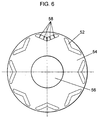
- Fig. 6 is a cross section illustrating a rotor of a motor, in which permanent magnets are embedded, in accordance with the fifth exemplary embodiment.
- Fig. 7A is a perspective view of the permanent magnets to be embedded into the rotor of the motor in accordance with the fifth exemplary embodiment, and
- Fig. 7B is a front view of the permanent magnets shown in Fig. 7A.
- Fig. 6 permanent magnets 52 are embedded in rotor 54, and rotary shaft 56 extends through the rotor center.
- This motor has a stator (not shown) disposed around rotor 54 via annular space.
- Magnet 52 is formed by laminating a plurality of rare-earth-sintered-magnet pieces. Air gaps 58 are provided between respective magnetic pieces. Magnet 52 is bowed toward the rotor center.
- Magnet 52 is further detailed with reference to Figs. 7A and 7B.
- Magnet 52 comprises rare-earth-sintered magnet.
- the rare-earth-sintered magnet is coated on its surface in order to avoid corrosion.
- Magnet 52 is formed by laminating six pieces of this rare-earth-sintered magnet.
- Two or more than two protrusions are provided on the respective faces laminated so that air gaps 58, as insulating layers, are provided to each magnet piece.
- the total area of the protrusions formed on each magnet piece should be smaller than the area of the face laminated, e.g. not more than 10% of the face laminated.
- the number of magnet pieces is not limited to six but other plural numbers are acceptable as far as they can provide air gaps between each magnet pieces.
- magnet 52 since magnet 52 has insulating layers (air gaps) between respective magnet pieces making up magnet 52, it is difficult for current to run through magnet 52. As a result, the production of eddy current is restrained. Meanwhile, magnet 52 employs a conductive coating material to avoid corrosion; however, the material can be insulating one, further, respective air gaps can be filled with insulating resin thereby enhancing the strength of magnet 52.
- the protrusions formed on each magnet piece can be made from another material and disposed on each magnet piece. Electrically insulating material among others for forming the protrusions can produce the advantage distinctly.
- Fig. 8A is a perspective view of permanent magnets to be embedded into a rotor of a motor in accordance with the sixth exemplary embodiment
- Fig. 8B is a front view of the permanent magnets shown in Fig. 8A.
- This sixth embodiment differs from the fifth one in a way splitting the magnet, and others stay the same.
- the magnet is split into six pieces in the axial direction; however, magnet 62 in this sixth embodiment is split into three pieces in a vertical direction with regard to the axial direction.
- the sixth embodiment can produce the same advantage as the fifth one has done.
- Fig. 9 is a perspective view of permanent magnets to be embedded into a rotor of a motor in accordance with the seventh exemplary embodiment of the present invention.
- This sixth embodiment differs from the fifth one in a way splitting the magnet, and others stay the same.
- the magnet is split into six pieces in the axial direction; however, magnet 72 in this seventh embodiment is split into three pieces in a rotating direction, and a center piece of the three pieces is further split into five pieces in the axial direction.
- the seventh embodiment can produce the same advantage as the fifth one has done.
- rare-earth-sintered magnet When rare-earth-sintered magnet is used as interior permanent magnets in the rotor, splitting the magnet effects the advantage distinctly because the rare-earth-sintered magnet has less electrical resistance and is easier for current to run through comparing with a ferrite magnet.
- the specific resistance of the ferrite magnet is not less than 10 -4 ⁇ ⁇ m, and that of the rare-earth-sintered magnet is ca. 10 -6 ⁇ ⁇ m.
- the rare-earth-sintered magnet allows the eddy current to run through more than 100 times in volume than the ferrite magnet does.
- the split of such magnet effectively restraints the production of eddy current.
- this motor includes the rotor with the interior magnet of the present invention.
- a motor with a stator wound by concentrated windings produces greater changes in the magnetic-flux-density when the motor is driven under weakening-magnetic-field control. Because in the motor having a rotor with interior permanent magnets, the magnetic-flux runs through the space between the magnets and the outer circumference of the rotor core, and thus the magnetic-flux is distributed unevenly between the rotor and the stator.
- the weakening-magnetic-field control applies inverse magnetic-filed to the motor so that the magnetic-flux produced by the magnet can be counteracted, therefore, this control method produces greater changes in the magnetic-flux than a regular control method does. Further the inverse magnetic-field narrows tolerance for irreversible demagnetization, and this produces a possibility of heat demagnetization at a temperature which is a matter of little concern in a normal condition.
- the weakening-magnetic-field-control thus produces distinctly an advantage of damping the heat generated by the eddy current.
- the motor used in the embodiments discussed above is an inner-rotor type, i.e. a rotor is disposed inside a stator, however, an outer-rotor type, i.e. a rotor is disposed outside a stator, and a linear motor, i.e. a rotor moves linearly with regard to a stator, produce the same advantages.
- the motor with interior permanent magnets of the present invention can restrain the production of eddy current and damp the heat demagnetization because the magnet is electrically split and thus an area of each magnet facing to the stator becomes narrower.
- the motor under the weakening-magnetic-field control can further damp the heat demagnetization.
- Fig. 10 is a block diagram of an electric vehicle in which the motor of the present invention is mounted.
- Body 80 of the electric vehicle is supported by wheels 81.
- This vehicle employs a front-wheel-drive method, so that motor 83 is directly connected to front-wheel-shaft 82.
- Motor 83 includes a stator being wound by concentrated windings and having interior permanent magnets as described in the exemplary embodiments previously discussed.
- Controller 84 controls the driving torque of motor 83, and battery 85 powers controller 84 and further powers motor 83. Motor 83 is thus driven, which then rotates wheels 81.
- the motor is employed to drive the wheels of the electric vehicle.
- the motor can be employed also to drive wheels of an electric locomotive.
Landscapes
- Engineering & Computer Science (AREA)
- Power Engineering (AREA)
- Transportation (AREA)
- Mechanical Engineering (AREA)
- Life Sciences & Earth Sciences (AREA)
- Sustainable Development (AREA)
- Sustainable Energy (AREA)
- Permanent Field Magnets Of Synchronous Machinery (AREA)
- Iron Core Of Rotating Electric Machines (AREA)
- Permanent Magnet Type Synchronous Machine (AREA)
Applications Claiming Priority (2)
| Application Number | Priority Date | Filing Date | Title |
|---|---|---|---|
| JP36916798 | 1998-12-25 | ||
| JP36916798 | 1998-12-25 |
Publications (3)
| Publication Number | Publication Date |
|---|---|
| EP1014542A2 true EP1014542A2 (fr) | 2000-06-28 |
| EP1014542A3 EP1014542A3 (fr) | 2001-01-31 |
| EP1014542B1 EP1014542B1 (fr) | 2005-11-16 |
Family
ID=18493740
Family Applications (1)
| Application Number | Title | Priority Date | Filing Date |
|---|---|---|---|
| EP99125812A Revoked EP1014542B1 (fr) | 1998-12-25 | 1999-12-23 | Moteur comportant des aimants fendus insérés dans le rotor |
Country Status (3)
| Country | Link |
|---|---|
| US (2) | US6340857B2 (fr) |
| EP (1) | EP1014542B1 (fr) |
| DE (1) | DE69928363T2 (fr) |
Cited By (12)
| Publication number | Priority date | Publication date | Assignee | Title |
|---|---|---|---|---|
| WO2002025796A1 (fr) * | 2000-09-21 | 2002-03-28 | Robert Bosch Gmbh | Machine electrique |
| DE10305905A1 (de) * | 2003-02-13 | 2004-08-26 | Bayerische Motoren Werke Ag | Elektromotor |
| WO2006095887A1 (fr) * | 2005-03-11 | 2006-09-14 | Toyota Jidosha Kabushiki Kaisha | Rotor de machine electrique rotative, machine electrique rotative et appareil d’entrainement de vehicule |
| WO2007006696A1 (fr) * | 2005-07-13 | 2007-01-18 | Siemens Aktiengesellschaft | Aimant en bloc presentant une protection contre la corrosion et utilisation dans des machines electriques |
| WO2007004009A3 (fr) * | 2005-06-30 | 2007-04-26 | Spal Automotive Srl | Rotor pour machine electrique |
| WO2007055803A1 (fr) * | 2005-10-31 | 2007-05-18 | Caterpillar Inc. | Dispositif comportant des pièces magnétiques permanentes |
| US7436096B2 (en) | 2005-10-31 | 2008-10-14 | Caterpillar Inc. | Rotor having permanent magnets and axialy-extending channels |
| US7436095B2 (en) | 2005-10-31 | 2008-10-14 | Caterpillar Inc. | Rotary electric machine |
| EP2139093A2 (fr) | 2008-06-27 | 2009-12-30 | Hitachi, Ltd. | Machine rotative électrique à aimants permanents |
| EP2995820A1 (fr) * | 2014-09-11 | 2016-03-16 | Pfeiffer Vacuum Gmbh | Pompe à vide avec rotor de moteur soudé et avec des aimants agencés en forme de v |
| EP3057201A1 (fr) * | 2015-02-16 | 2016-08-17 | ALSTOM Transport Technologies | Rotor de moteur électrique et moteur électrique correspondant |
| EP1458080B1 (fr) * | 2001-12-20 | 2017-03-01 | Mitsubishi Denki Kabushiki Kaisha | Machine dynamoelectrique du type a aimants permanents et generateur synchrone du type a aimants permanents utilisant l'energie eolienne |
Families Citing this family (88)
| Publication number | Priority date | Publication date | Assignee | Title |
|---|---|---|---|---|
| JP3906882B2 (ja) * | 1997-10-24 | 2007-04-18 | 株式会社富士通ゼネラル | 永久磁石電動機 |
| JP3906883B2 (ja) * | 1997-10-29 | 2007-04-18 | 株式会社富士通ゼネラル | 永久磁石電動機 |
| US6340857B2 (en) * | 1998-12-25 | 2002-01-22 | Matsushita Electric Industrial Co., Ltd. | Motor having a rotor with interior split-permanent-magnet |
| FR2791483B1 (fr) * | 1999-03-22 | 2004-06-25 | Valeo Equip Electr Moteur | Machine tournante comportant des aimants de compositions differentes |
| JP2001314052A (ja) * | 2000-02-25 | 2001-11-09 | Nissan Motor Co Ltd | 同期電動機のロータ構造 |
| US6891299B2 (en) * | 2000-05-03 | 2005-05-10 | Moteurs Leroy-Somer | Rotary electric machine having a flux-concentrating rotor and a stator with windings on teeth |
| US6917133B2 (en) | 2000-08-29 | 2005-07-12 | Hitachi, Ltd. | Air conditioner having permanent magnet rotating electric machine |
| JP3787756B2 (ja) * | 2000-08-29 | 2006-06-21 | 株式会社日立製作所 | 永久磁石式回転電機 |
| JP2002112593A (ja) * | 2000-09-27 | 2002-04-12 | Hideo Kawamura | 複数系統の電力発電特性を持つ発電装置 |
| JP3707539B2 (ja) * | 2001-03-02 | 2005-10-19 | 日産自動車株式会社 | 電動機または発電機 |
| JP3748387B2 (ja) * | 2001-04-05 | 2006-02-22 | 株式会社日立製作所 | 永久磁石式回転電機及びそれを用いた発電システムと駆動システム |
| FR2823614B1 (fr) * | 2001-04-17 | 2008-07-11 | Leroy Somer Moteurs | Machine tournante electrique comportant un stator forme de secteurs assembles |
| US20020171305A1 (en) * | 2001-04-17 | 2002-11-21 | Moteurs Leroy-Somer | Electric machine having an outer rotor |
| JP2003047185A (ja) * | 2001-07-31 | 2003-02-14 | Nissan Motor Co Ltd | 永久磁石式回転電機 |
| US6867526B2 (en) * | 2001-09-05 | 2005-03-15 | Koyo Seiko Co., Ltd. | Brushless DC motor |
| JP2003092863A (ja) * | 2001-09-20 | 2003-03-28 | Nissan Motor Co Ltd | 永久磁石埋込同期モータ |
| DE10147310B4 (de) * | 2001-09-26 | 2004-06-17 | Vacuumschmelze Gmbh & Co. Kg | Schalenförmiger Magnet |
| JP2003164083A (ja) * | 2001-11-22 | 2003-06-06 | Shin Etsu Chem Co Ltd | 永久磁石及びモータ |
| US20030214194A1 (en) * | 2002-05-20 | 2003-11-20 | General Electric Company | Rotor assembly and method of making |
| US6936937B2 (en) * | 2002-06-14 | 2005-08-30 | Sunyen Co., Ltd. | Linear electric generator having an improved magnet and coil structure, and method of manufacture |
| US20040251763A1 (en) * | 2003-06-13 | 2004-12-16 | Matsushita Electric Industrial Co., Ltd. | Motor |
| US6847144B1 (en) * | 2003-12-10 | 2005-01-25 | Industrial Technology Research Institute | Permanent magnet rotor assembly for interior permanent magnet electric motor |
| DE102004017157B4 (de) * | 2004-04-07 | 2007-04-19 | Minebea Co., Ltd. | Verfahren zur Herstellung einer Rotoranordnung und Rotoranordnung für eine elektrische Maschine |
| US7474029B2 (en) * | 2004-06-14 | 2009-01-06 | General Motors Corporation | Rotor magnet placement in interior permanent magnet machines |
| US20060022541A1 (en) * | 2004-07-30 | 2006-02-02 | Raymond Ong | Rotor hub and assembly for a permanent magnet power electric machine |
| FR2876229B1 (fr) * | 2004-10-05 | 2008-09-05 | Alstom Transport Sa | Rotor pour moteur electrique et moteur electrique correspondant. |
| US20070159021A1 (en) * | 2005-12-19 | 2007-07-12 | Emerson Electric Co. | Composite magnet structure for rotor |
| JP4270203B2 (ja) * | 2005-12-21 | 2009-05-27 | ダイキン工業株式会社 | モータおよび圧縮機 |
| DE102006004537A1 (de) * | 2006-02-01 | 2007-08-02 | Volkswagen Ag | Elektrische Maschine |
| US7385328B2 (en) * | 2006-05-23 | 2008-06-10 | Reliance Electric Technologies, Llc | Cogging reduction in permanent magnet machines |
| US7851958B2 (en) * | 2006-06-12 | 2010-12-14 | Remy International, Inc. | Electric machine with interior permanent magnets |
| JP5157138B2 (ja) * | 2006-11-24 | 2013-03-06 | 株式会社日立製作所 | 永久磁石式回転電機及び風力発電システム |
| US7898135B2 (en) * | 2007-03-07 | 2011-03-01 | Qm Power, Inc. | Hybrid permanent magnet motor |
| US7932658B2 (en) * | 2007-03-15 | 2011-04-26 | A.O. Smith Corporation | Interior permanent magnet motor including rotor with flux barriers |
| JP4404223B2 (ja) | 2007-03-20 | 2010-01-27 | 株式会社安川電機 | 電磁鋼板形成体、電磁鋼板積層体、これを備えた永久磁石形同期回転電機用回転子、永久磁石形同期回転電機、該回転電機を用いた車両、昇降機、流体機械、加工機 |
| JP2008245336A (ja) * | 2007-03-23 | 2008-10-09 | Toshiba Corp | 回転子及び永久磁石回転電機 |
| WO2008119055A1 (fr) * | 2007-03-27 | 2008-10-02 | Qm Power, Inc. | Dispositif électromécanique à aimant permanent fournissant des fonctions de moteur/de générateur |
| WO2008137709A2 (fr) * | 2007-05-04 | 2008-11-13 | A. O. Smith Corporation | Moteur et rotor à aimants permanents internes |
| JP4466681B2 (ja) * | 2007-05-11 | 2010-05-26 | トヨタ自動車株式会社 | 回転電機のロータおよび回転電機 |
| US7847461B2 (en) * | 2007-06-06 | 2010-12-07 | Gm Global Technology Operations, Inc. | Multi-layer magnet arrangement in a permanent magnet machine for a motorized vehicle |
| JP2009118619A (ja) * | 2007-11-06 | 2009-05-28 | Honda Motor Co Ltd | モータ用永久磁石 |
| US20100013346A1 (en) * | 2008-07-21 | 2010-01-21 | Joseph Peek | Low speed, permanent magnet brushless motors and generators |
| EP2304863B1 (fr) * | 2008-07-30 | 2018-06-27 | Regal Beloit America, Inc. | Moteur à aimants permanents intérieurs comprenant un rotor avec des pôles inégaux |
| JP5433198B2 (ja) | 2008-10-16 | 2014-03-05 | 日立オートモティブシステムズ株式会社 | 回転電機及び電気自動車 |
| US20100253169A1 (en) * | 2009-04-01 | 2010-10-07 | General Electric Company | Electric machine |
| US8222787B2 (en) * | 2009-04-01 | 2012-07-17 | General Electric Company | Electric machine |
| DE102009031371B4 (de) * | 2009-07-01 | 2011-05-26 | Siemens Aktiengesellschaft | Läufer und Verfahren zur Herstellung eines Läufers einer elektrischen Maschine |
| JP5589345B2 (ja) * | 2009-10-21 | 2014-09-17 | 富士電機株式会社 | 永久磁石式回転電機 |
| US20110101817A1 (en) * | 2009-11-05 | 2011-05-05 | Gm Global Technology Operations, Inc. | Variable geometry electric machine |
| JP5408340B2 (ja) * | 2010-03-30 | 2014-02-05 | Tdk株式会社 | 希土類焼結磁石及びその製造方法、並びにモータ及び自動車 |
| JP2012099523A (ja) | 2010-10-29 | 2012-05-24 | Shin Etsu Chem Co Ltd | 異方性希土類焼結磁石及びその製造方法 |
| US8446121B1 (en) * | 2010-11-19 | 2013-05-21 | The Boeing Company | High performance actuator motor |
| JP2012228104A (ja) * | 2011-04-21 | 2012-11-15 | Mitsubishi Electric Corp | 永久磁石埋込型電動機 |
| CN202395533U (zh) * | 2011-06-16 | 2012-08-22 | 尤里·拉波波特 | 发电机 |
| US8618708B2 (en) * | 2011-07-29 | 2013-12-31 | General Electric Company | Electrical machine |
| US20130249342A1 (en) * | 2012-03-20 | 2013-09-26 | Kollmorgen Corporation | Cantilevered Rotor Magnet Support |
| JP5974599B2 (ja) * | 2012-04-12 | 2016-08-23 | 株式会社デンソー | 回転電機 |
| US9035520B2 (en) | 2012-05-24 | 2015-05-19 | Kollmorgen Corporation | Rotor lamination stress relief |
| US10008892B2 (en) * | 2012-05-31 | 2018-06-26 | Edwards Japan Limited | IPM motor for vacuum pump |
| DE102012010993A1 (de) * | 2012-06-02 | 2013-12-05 | Volkswagen Aktiengesellschaft | Rotor für einen Elektromotor |
| US20140054999A1 (en) * | 2012-08-27 | 2014-02-27 | Remy Technologies, Llc | Method of manufacturing an electric machine with segmented permanent magnets |
| US9882440B2 (en) | 2012-10-15 | 2018-01-30 | Regal Beloit America, Inc. | Radially embedded permanent magnet rotor and methods thereof |
| US9099905B2 (en) | 2012-10-15 | 2015-08-04 | Regal Beloit America, Inc. | Radially embedded permanent magnet rotor and methods thereof |
| US9362792B2 (en) | 2012-10-15 | 2016-06-07 | Regal Beloit America, Inc. | Radially embedded permanent magnet rotor having magnet retention features and methods thereof |
| US9246364B2 (en) | 2012-10-15 | 2016-01-26 | Regal Beloit America, Inc. | Radially embedded permanent magnet rotor and methods thereof |
| US9831727B2 (en) | 2012-10-15 | 2017-11-28 | Regal Beloit America, Inc. | Permanent magnet rotor and methods thereof |
| JP2014100028A (ja) * | 2012-11-15 | 2014-05-29 | Toyota Industries Corp | 車両駆動装置 |
| JP6128419B2 (ja) * | 2013-01-15 | 2017-05-17 | 日本電産株式会社 | 回転電機 |
| US9641054B2 (en) * | 2013-05-17 | 2017-05-02 | General Electric Company | Segmented magnet component for electric machine and method of assembly |
| ES2705549T3 (es) | 2013-06-20 | 2019-03-25 | Otis Elevator Co | Máquina eléctrica que tiene un rotor con imanes permanentes inclinados |
| US9698660B2 (en) | 2013-10-25 | 2017-07-04 | General Electric Company | System and method for heating ferrite magnet motors for low temperatures |
| WO2015083274A1 (fr) * | 2013-12-05 | 2015-06-11 | 三菱電機株式会社 | Moteur électrique à aimants permanents intégrés, compresseur, et dispositif de conditionnement d'air |
| KR101534706B1 (ko) * | 2013-12-18 | 2015-07-07 | 현대자동차 주식회사 | 매입형 영구자석 동기모터 |
| US10110077B2 (en) * | 2014-08-21 | 2018-10-23 | Mitsubishi Electric Corporation | Permanent-magnet-embedded electric motor and compressor |
| US9602043B2 (en) | 2014-08-29 | 2017-03-21 | General Electric Company | Magnet management in electric machines |
| DE102014019218A1 (de) | 2014-12-19 | 2015-06-25 | Daimler Ag | Blechpaket für eine elektrische Maschine |
| JP6506649B6 (ja) * | 2015-07-27 | 2019-06-05 | 日立グローバルライフソリューションズ株式会社 | 永久磁石同期機及びそれを用いた機器 |
| JP6753233B2 (ja) * | 2016-09-08 | 2020-09-09 | Tdk株式会社 | 磁石、磁石積層体およびモータ |
| JP7009069B2 (ja) * | 2017-03-08 | 2022-01-25 | Tdk株式会社 | 磁石積層体およびモータ |
| TWM576750U (zh) | 2017-07-25 | 2019-04-11 | 美商米沃奇電子工具公司 | 電氣組合物、電動化裝置系統、電池組、電馬達、馬達總成及電馬達總成 |
| CN109412290A (zh) * | 2017-08-15 | 2019-03-01 | 大银微系统股份有限公司 | 永磁马达 |
| US10230321B1 (en) | 2017-10-23 | 2019-03-12 | General Electric Company | System and method for preventing permanent magnet demagnetization in electrical machines |
| EP3917708A4 (fr) | 2019-02-18 | 2022-11-30 | Milwaukee Electric Tool Corporation | Outil à percussion |
| WO2021081372A1 (fr) * | 2019-10-25 | 2021-04-29 | Jacobi Motors LLC | Moteur à mémoire à flux variable |
| US11349377B2 (en) * | 2020-01-27 | 2022-05-31 | Ford Global Technologies, Llc | Electric machine for a hybrid or electric vehicle |
| JP7478104B2 (ja) * | 2021-01-08 | 2024-05-02 | 株式会社アイシン | ロータコア |
| CN112803449B (zh) * | 2021-01-29 | 2024-07-09 | 鸿鲲新能源(海南)有限公司 | 可调式电励磁筒式涡流制热器及其制热方法 |
| CN219372112U (zh) * | 2022-12-30 | 2023-07-18 | 华为数字能源技术有限公司 | 磁钢、径向磁通电机、动力总成及车辆 |
Family Cites Families (23)
| Publication number | Priority date | Publication date | Assignee | Title |
|---|---|---|---|---|
| US4139790A (en) * | 1977-08-31 | 1979-02-13 | Reliance Electric Company | Direct axis aiding permanent magnets for a laminated synchronous motor rotor |
| US4510680A (en) * | 1982-12-27 | 1985-04-16 | General Electric Company | Method of making a permanent magnet rotor |
| US4480207A (en) * | 1982-12-27 | 1984-10-30 | General Electric Company | Permanent magnet rotor and method of making same |
| JPS6028758A (ja) * | 1983-07-27 | 1985-02-13 | Hitachi Ltd | 永久磁石を有する回転電機 |
| US4845837A (en) | 1986-10-06 | 1989-07-11 | Emerson Electric Co. | Method of making permanent magnet assembly |
| US4935080A (en) * | 1988-01-29 | 1990-06-19 | Kollmorgen Corporation | Protection and bonding of neodymium-boron-iron magnets used in the formation of magnet assemblies |
| US5191256A (en) * | 1989-12-15 | 1993-03-02 | American Motion Systems | Interior magnet rotary machine |
| US5641363A (en) * | 1993-12-27 | 1997-06-24 | Tdk Corporation | Sintered magnet and method for making |
| FR2723272B1 (fr) | 1994-07-27 | 1996-08-30 | Gec Alsthom Parvex Sa | Moteur synchrone comportant des aimants inseres dans un rotor |
| JP3371314B2 (ja) | 1995-03-24 | 2003-01-27 | セイコーエプソン株式会社 | Dcブラシレスモータおよび制御装置 |
| JPH08331784A (ja) * | 1995-03-24 | 1996-12-13 | Hitachi Metals Ltd | 永久磁石界磁方式回転機 |
| JP3397019B2 (ja) * | 1995-04-21 | 2003-04-14 | 三菱電機株式会社 | 永久磁石形モータ |
| JPH09308A (ja) * | 1995-06-22 | 1997-01-07 | Toyobo Co Ltd | 靴用下敷材 |
| EP0823771B1 (fr) | 1996-02-23 | 2006-04-26 | Matsushita Electric Industrial Co., Ltd. | Moteur |
| JP3351237B2 (ja) | 1996-05-16 | 2002-11-25 | 三菱電機株式会社 | 永久磁石形モータ |
| ATE197360T1 (de) | 1996-05-21 | 2000-11-15 | Siemens Ag | Dauermagneterregte synchronmaschine |
| JPH09327140A (ja) * | 1996-06-07 | 1997-12-16 | Hitachi Ltd | 永久磁石回転型回転電機及びその製造方法 |
| KR100252393B1 (ko) | 1997-05-13 | 2000-04-15 | 윤종용 | 영구자석매립형회전자구조 |
| US6008559A (en) * | 1997-07-22 | 1999-12-28 | Matsushita Electric Industrial Co., Ltd. | Motor using a rotor including an interior permanent magnet |
| JPH1198731A (ja) * | 1997-07-22 | 1999-04-09 | Matsushita Electric Ind Co Ltd | 永久磁石を埋設したロータを用いたモータ |
| JP3906882B2 (ja) * | 1997-10-24 | 2007-04-18 | 株式会社富士通ゼネラル | 永久磁石電動機 |
| JP3462058B2 (ja) * | 1997-11-07 | 2003-11-05 | ミネベア株式会社 | モータ構造 |
| US6340857B2 (en) * | 1998-12-25 | 2002-01-22 | Matsushita Electric Industrial Co., Ltd. | Motor having a rotor with interior split-permanent-magnet |
-
1999
- 1999-12-23 US US09/471,375 patent/US6340857B2/en not_active Expired - Lifetime
- 1999-12-23 EP EP99125812A patent/EP1014542B1/fr not_active Revoked
- 1999-12-23 DE DE69928363T patent/DE69928363T2/de not_active Expired - Lifetime
-
2001
- 2001-12-07 US US10/004,851 patent/US6741002B2/en not_active Expired - Fee Related
Cited By (21)
| Publication number | Priority date | Publication date | Assignee | Title |
|---|---|---|---|---|
| WO2002025796A1 (fr) * | 2000-09-21 | 2002-03-28 | Robert Bosch Gmbh | Machine electrique |
| US6703756B2 (en) | 2000-09-21 | 2004-03-09 | Robert Bosch Gmbh | Electrical machine |
| EP1458080B1 (fr) * | 2001-12-20 | 2017-03-01 | Mitsubishi Denki Kabushiki Kaisha | Machine dynamoelectrique du type a aimants permanents et generateur synchrone du type a aimants permanents utilisant l'energie eolienne |
| DE10305905A1 (de) * | 2003-02-13 | 2004-08-26 | Bayerische Motoren Werke Ag | Elektromotor |
| WO2006095887A1 (fr) * | 2005-03-11 | 2006-09-14 | Toyota Jidosha Kabushiki Kaisha | Rotor de machine electrique rotative, machine electrique rotative et appareil d’entrainement de vehicule |
| WO2007004009A3 (fr) * | 2005-06-30 | 2007-04-26 | Spal Automotive Srl | Rotor pour machine electrique |
| US8405269B2 (en) | 2005-06-30 | 2013-03-26 | Spal Automotive S.R.L. | Rotor for an electrical machine |
| AU2006264597B2 (en) * | 2005-06-30 | 2010-11-25 | Spal Automotive S.R.L. | A rotor for an electrical machine |
| WO2007006696A1 (fr) * | 2005-07-13 | 2007-01-18 | Siemens Aktiengesellschaft | Aimant en bloc presentant une protection contre la corrosion et utilisation dans des machines electriques |
| WO2007055803A1 (fr) * | 2005-10-31 | 2007-05-18 | Caterpillar Inc. | Dispositif comportant des pièces magnétiques permanentes |
| US7504754B2 (en) | 2005-10-31 | 2009-03-17 | Caterpillar Inc. | Rotor having multiple permanent-magnet pieces in a cavity |
| US7436095B2 (en) | 2005-10-31 | 2008-10-14 | Caterpillar Inc. | Rotary electric machine |
| US7436096B2 (en) | 2005-10-31 | 2008-10-14 | Caterpillar Inc. | Rotor having permanent magnets and axialy-extending channels |
| EP2139093A2 (fr) | 2008-06-27 | 2009-12-30 | Hitachi, Ltd. | Machine rotative électrique à aimants permanents |
| EP2139093A3 (fr) * | 2008-06-27 | 2011-07-13 | Hitachi, Ltd. | Machine rotative électrique à aimants permanents |
| EP2995820A1 (fr) * | 2014-09-11 | 2016-03-16 | Pfeiffer Vacuum Gmbh | Pompe à vide avec rotor de moteur soudé et avec des aimants agencés en forme de v |
| EP3057201A1 (fr) * | 2015-02-16 | 2016-08-17 | ALSTOM Transport Technologies | Rotor de moteur électrique et moteur électrique correspondant |
| FR3032839A1 (fr) * | 2015-02-16 | 2016-08-19 | Alstom Transp Tech | Rotor de moteur electrique et moteur electrique correspondant |
| CN105896769A (zh) * | 2015-02-16 | 2016-08-24 | 阿尔斯通运输科技公司 | 电机转子及相关的电机 |
| US10270302B2 (en) | 2015-02-16 | 2019-04-23 | Alstom Transport Technologies | Electric motor rotor and electric motor associated |
| CN105896769B (zh) * | 2015-02-16 | 2020-08-18 | 阿尔斯通运输科技公司 | 电机转子及相关的电机 |
Also Published As
| Publication number | Publication date |
|---|---|
| DE69928363D1 (de) | 2005-12-22 |
| EP1014542B1 (fr) | 2005-11-16 |
| US6741002B2 (en) | 2004-05-25 |
| EP1014542A3 (fr) | 2001-01-31 |
| US20010043020A1 (en) | 2001-11-22 |
| US20020041128A1 (en) | 2002-04-11 |
| US6340857B2 (en) | 2002-01-22 |
| DE69928363T2 (de) | 2006-06-01 |
Similar Documents
| Publication | Publication Date | Title |
|---|---|---|
| US6340857B2 (en) | Motor having a rotor with interior split-permanent-magnet | |
| US6452302B1 (en) | Rotary electric machine and electric vehicle using the same | |
| US7535145B2 (en) | Axial air gap-type electric motor | |
| US7595575B2 (en) | Motor/generator to reduce cogging torque | |
| JP3308828B2 (ja) | 永久磁石回転電機及びそれを用いた電動車両 | |
| CN102265483B (zh) | 轴向磁通电动机和发电机总成 | |
| EP1032115B1 (fr) | Machine tournante à reluctance avec aimants permanents | |
| KR200210795Y1 (ko) | 영구자석 매립형 모터 | |
| US9461511B2 (en) | Electric machine with permanently excited armature and associated permanently excited armature | |
| JP6539004B1 (ja) | 回転子および回転電機 | |
| US7902700B1 (en) | Low harmonic loss brushless motor | |
| KR100615878B1 (ko) | Ipm 모터, 모터구동차량, 전기자동차 및 전차 | |
| JP2000245085A (ja) | モータ | |
| JP3602392B2 (ja) | 永久磁石埋め込みモータ | |
| EP1096648B1 (fr) | Moteur/générateur avec deux rotors | |
| JP2011050216A (ja) | 電動機 | |
| JPH08251848A (ja) | 永久磁石形同期回転電機のロータ | |
| JPH10322948A (ja) | 永久磁石埋込形回転子 | |
| JP2008136298A (ja) | 回転電機の回転子及び回転電機 | |
| JP3835231B2 (ja) | 電動機 | |
| JP3722166B2 (ja) | 永久磁石形電動機の界磁 | |
| JP3703907B2 (ja) | ブラシレスdcモータ | |
| JP4735772B1 (ja) | 磁石励磁回転電機システム | |
| JP3772819B2 (ja) | 同軸モータのロータ構造 | |
| US20220085674A1 (en) | Rotary electric machine |
Legal Events
| Date | Code | Title | Description |
|---|---|---|---|
| PUAI | Public reference made under article 153(3) epc to a published international application that has entered the european phase |
Free format text: ORIGINAL CODE: 0009012 |
|
| AK | Designated contracting states |
Kind code of ref document: A2 Designated state(s): DE FR GB |
|
| AX | Request for extension of the european patent |
Free format text: AL;LT;LV;MK;RO;SI |
|
| PUAL | Search report despatched |
Free format text: ORIGINAL CODE: 0009013 |
|
| AK | Designated contracting states |
Kind code of ref document: A3 Designated state(s): AT BE CH CY DE DK ES FI FR GB GR IE IT LI LU MC NL PT SE |
|
| AX | Request for extension of the european patent |
Free format text: AL;LT;LV;MK;RO;SI |
|
| 17P | Request for examination filed |
Effective date: 20010509 |
|
| AKX | Designation fees paid |
Free format text: DE FR GB |
|
| 17Q | First examination report despatched |
Effective date: 20030401 |
|
| GRAP | Despatch of communication of intention to grant a patent |
Free format text: ORIGINAL CODE: EPIDOSNIGR1 |
|
| GRAS | Grant fee paid |
Free format text: ORIGINAL CODE: EPIDOSNIGR3 |
|
| GRAA | (expected) grant |
Free format text: ORIGINAL CODE: 0009210 |
|
| AK | Designated contracting states |
Kind code of ref document: B1 Designated state(s): DE FR GB |
|
| REG | Reference to a national code |
Ref country code: GB Ref legal event code: FG4D |
|
| RIN1 | Information on inventor provided before grant (corrected) |
Inventor name: KONDO, YASUHIRO Inventor name: OGUSHI, MASAKI Inventor name: IKKAI, YASUFUMI Inventor name: NAKAMURA, TOMOKAZU Inventor name: NISHIYAMA, NORIYOSHI |
|
| REF | Corresponds to: |
Ref document number: 69928363 Country of ref document: DE Date of ref document: 20051222 Kind code of ref document: P |
|
| ET | Fr: translation filed | ||
| PLBI | Opposition filed |
Free format text: ORIGINAL CODE: 0009260 |
|
| 26 | Opposition filed |
Opponent name: SIEMENS AG Effective date: 20060816 |
|
| PLAX | Notice of opposition and request to file observation + time limit sent |
Free format text: ORIGINAL CODE: EPIDOSNOBS2 |
|
| PLBB | Reply of patent proprietor to notice(s) of opposition received |
Free format text: ORIGINAL CODE: EPIDOSNOBS3 |
|
| PLAB | Opposition data, opponent's data or that of the opponent's representative modified |
Free format text: ORIGINAL CODE: 0009299OPPO |
|
| RAP2 | Party data changed (patent owner data changed or rights of a patent transferred) |
Owner name: PANASONIC CORPORATION |
|
| PLCK | Communication despatched that opposition was rejected |
Free format text: ORIGINAL CODE: EPIDOSNREJ1 |
|
| APBM | Appeal reference recorded |
Free format text: ORIGINAL CODE: EPIDOSNREFNO |
|
| APBP | Date of receipt of notice of appeal recorded |
Free format text: ORIGINAL CODE: EPIDOSNNOA2O |
|
| APAH | Appeal reference modified |
Free format text: ORIGINAL CODE: EPIDOSCREFNO |
|
| APBQ | Date of receipt of statement of grounds of appeal recorded |
Free format text: ORIGINAL CODE: EPIDOSNNOA3O |
|
| PGFP | Annual fee paid to national office [announced via postgrant information from national office to epo] |
Ref country code: GB Payment date: 20121219 Year of fee payment: 14 |
|
| PGFP | Annual fee paid to national office [announced via postgrant information from national office to epo] |
Ref country code: FR Payment date: 20130107 Year of fee payment: 14 |
|
| PGFP | Annual fee paid to national office [announced via postgrant information from national office to epo] |
Ref country code: DE Payment date: 20121219 Year of fee payment: 14 |
|
| REG | Reference to a national code |
Ref country code: DE Ref legal event code: R103 Ref document number: 69928363 Country of ref document: DE Ref country code: DE Ref legal event code: R064 Ref document number: 69928363 Country of ref document: DE |
|
| APBU | Appeal procedure closed |
Free format text: ORIGINAL CODE: EPIDOSNNOA9O |
|
| RDAF | Communication despatched that patent is revoked |
Free format text: ORIGINAL CODE: EPIDOSNREV1 |
|
| RDAG | Patent revoked |
Free format text: ORIGINAL CODE: 0009271 |
|
| STAA | Information on the status of an ep patent application or granted ep patent |
Free format text: STATUS: PATENT REVOKED |
|
| 27W | Patent revoked |
Effective date: 20130912 |
|
| GBPR | Gb: patent revoked under art. 102 of the ep convention designating the uk as contracting state |
Effective date: 20130912 |
|
| REG | Reference to a national code |
Ref country code: DE Ref legal event code: R107 Ref document number: 69928363 Country of ref document: DE Effective date: 20140220 |