EP1014553A2 - Verfahren und Vorrichtung zur Synchronisierungsregelung - Google Patents
Verfahren und Vorrichtung zur Synchronisierungsregelung Download PDFInfo
- Publication number
- EP1014553A2 EP1014553A2 EP99123911A EP99123911A EP1014553A2 EP 1014553 A2 EP1014553 A2 EP 1014553A2 EP 99123911 A EP99123911 A EP 99123911A EP 99123911 A EP99123911 A EP 99123911A EP 1014553 A2 EP1014553 A2 EP 1014553A2
- Authority
- EP
- European Patent Office
- Prior art keywords
- phase
- electric motor
- rotational frequency
- section
- slave
- Prior art date
- Legal status (The legal status is an assumption and is not a legal conclusion. Google has not performed a legal analysis and makes no representation as to the accuracy of the status listed.)
- Granted
Links
Images


Classifications
-
- H—ELECTRICITY
- H02—GENERATION; CONVERSION OR DISTRIBUTION OF ELECTRIC POWER
- H02P—CONTROL OR REGULATION OF ELECTRIC MOTORS, ELECTRIC GENERATORS OR DYNAMO-ELECTRIC CONVERTERS; CONTROLLING TRANSFORMERS, REACTORS OR CHOKE COILS
- H02P5/00—Arrangements specially adapted for regulating or controlling the speed or torque of two or more electric motors
- H02P5/46—Arrangements specially adapted for regulating or controlling the speed or torque of two or more electric motors for speed regulation of two or more dynamo-electric motors in relation to one another
- H02P5/52—Arrangements specially adapted for regulating or controlling the speed or torque of two or more electric motors for speed regulation of two or more dynamo-electric motors in relation to one another additionally providing control of relative angular displacement
- H02P5/56—Speed and position comparison between the motors by electrical means
Definitions
- the present invention relates to a device and a method for controlling synchronization where machine shafts are electrically-driven and in phased synchronism by plural, mutually accurate, electric motors.
- Such shafts may be found in conveyor systems, processing systems for resins and metals, and rotary presses.
- a conventional method uses an origin detector provided on each electric motor or each rotating machine shaft to detect a machine origin. The electric motor is then interrupted, and the origins of all other electric motors are then detected. When detection of all origins for all motors is complete, synchronous operation is begun. In this way, a time of 30 to 50 seconds is required until the matching has been completed. This lengthens waiting time, causing poor working efficiency.
- a recently proposed method matches the origins of plural electric motors in an improved manner, i.e., the matching of origins is achieved without once interrupting the electric motors during low rotational frequency operation.
- FIG. 6 illustrates a prior art example in which matching of origins is effected during low rotational frequency operation of electric motors.
- two electric motors are exemplarily used in the matching of origins of plural electric motors for brevity of the description.
- Mm, Ms1 are electric motors in a master section and a slave section
- Pm, Ps1 are incremental encoders each coupled with the machine shafts driven by the electric motors
- Rm, Rs1 are the rotating machine shafts driven by the electric motors.
- Machine origins Gm, Gs1 are mounted on the machine shafts Rm, Rs1, which origins are detected by detectors Km, Ks1.
- the aforementioned master and slave electric motors Mm, Ms1 are driven respectively by drivers Dm, Ds1 and controllers Am, As1.
- the aforesaid controller Am drives the electric motor Mm through the driver Dm following a rotational frequency instruction provided from a concentrated controller C by obtaining a rotational frequency signal through a rotational frequency detector Fm from a continuous pulse signal outputted by the aforementioned incremental encoder Pm, and feeding the rotational frequency signal back.
- a rotational frequency instruction is detected by the rotational frequency detector Ssl from the pulse signal obtained from the aforementioned incremental encoder Pm of the master section. Further, a feedback rotational frequency of the slave section is detected from the incremental encoder Psl and the rotational frequency detector Fsl of the slave section.
- a cumulative counter Csl is cleared when the aforesaid detector Km of the master section detects the machine origin, and counts a pulse train of the aforesaid incremental encoder Psl of the slave section.
- the counted value of the cumulative counter Csl is stored in a Z correlation distance memory area Zsl with the aid of a switch RYsl, actuated when the detector Ksl of the slave section detects the machine origin. More specifically, the stored value in the Z correlation distance memory part Zsl indicates a Z correlation distance ⁇ obtained by measuring the phase difference of the mechanical origins of the master and the slave with the number of pulses of the aforesaid Psl of the slave section.
- Two electric motors are matched in origins thereof by adjusting the rotational frequency of the slave section as described above, and are changed over to synchronization control and then accelerated into ordinary rotational frequency operation.
- the prior art method and apparatus suffer from difficulties that even when the origin matching is effected while operating the electric motors, the Z correlation distance ⁇ is detected by allowing the electric motors of the master and slave to rotate by one revolution or more, so that much time is required for the detection, and it takes 20 to 40 seconds until the origin matching is completed.
- one electric motor is disposed in a master section and the other one or plural electric motors is or are disposed in a slave section.
- a rotary encoder composed of an absolute encoder or a Z phase equipped incremental encoder is provided on the electric motors of the master section and the slave section or on machine shafts driven by the electric motors to output a signal in response to rotation of the electric motor or the machine shaft.
- rotary encoder there may be employed one attached to each electric motor (rotary encoder mounted on the electric motor for detecting rotation of the electric motor), and the rotary encoder may be coupled with a machine shaft connected with a rotary shaft of each electric motor or coupled with a machine shaft connected through a gear and the like.
- the electric motor of the master section is driven by ordinary rotational frequency control.
- a controller of the electric motor of the slave section detects at all times both a rotational frequency and a rotation phase of the aforesaid electric motor or the machine shaft based upon a signal from the rotary encoder of the master section, and detects at all times both a rotational frequency and a rotation phase of the electric motor of the slave or the machine shaft driven by the electric motor based upon a signal from the rotary encoder of the slave section.
- the controller of the electric motor of the slave section calculates at all times a synchronization phase deviation from the rotation phase of the master and it of the slave both detected at all times as described above.
- the synchronization control device constructed as described above, when plural electric motors are all operated from a stopped state, they are increased in their rotational frequency first from a low rotational frequency to a predetermined rotational frequency irrespective of an ordinary rotational frequency.
- the electric motor of the master section is increased in its rotational frequency with ordinary rotational frequency control, and the electric motor of the slave section or the machine shaft driven by the electric motor is increased in its rotational frequency taking a signal detected from the rotary encoder of the master section as a rotational frequency instruction.
- each slave section After the electric motor of each slave section is in acceleration or reaches a predetermined rotational frequency, the synchronization phase deviation of the master and the slave calculated at all times is added to the rotational frequency instruction as a correction value.
- Each slave section rapidly completes the origin matching as described above.
- Each slave section adds at all times the synchronization phase deviation of the master and slave sections to the rotational frequency instruction as a correction value even after the origin matching is completed, and clearly continues the synchronization control with the same action as the origin matching even under ordinary operation on and after the operation.
- the electric motor is provided on the master section, and a rotational frequency signal and a phase signal are outputted from the rotary encoder attached to the electric motor provided on the master section or coupled with the machine shaft driven by the electric motor, a rotational frequency signal and a phase signal corresponding to the signal outputted from the aforesaid rotary encoder are electronically generated without provision of the electric motor on the master section and are outputted from the master section, and the rotation phase of the electric motor of the slave section or of the machine shaft driven by the electric motor may be controlled on the basis of the rotational frequency signal and the phase signal.
- the synchronization phase deviation of the master and the slave is detected at all times, which deviation is in turn employed as a correction signal to rapidly complete the origin matching and eliminate the need of a changeover of the control upon the origin matching and in transfer to ordinary synchronization control and hence bring very high practicability.
- the origin matching is clearly ensured even in acceleration without waiting arrival to a predetermined rotational frequency.
- the stopped electric motors of the slave section are started, and the rotational frequency of the master section detected from the rotary encoder of the master section is increased as the rotational frequency instruction.
- the slave section after reaching a predetermined rotational frequency, adds the synchronization phase deviation of the slave and the master to the rotational frequency instruction as a correction.
- the slave section rapidly completes the original point matching and shifts the operation to the synchronization control.
- FIG. 1 illustrates a preferred embodiment of the present invention where plural electric motors are matched in origins thereof
- Figs. 2, 3, 4, and 5 are views each illustrating operation of a preferred embodiment illustrated in FIG. 1.
- FIG. 1 exemplarily illustrates synchronization control of a master section and two slave sections in order to simply describe plural electric motors according to the present invention, in which the same symbols shall be applied to portions overlapping on portions in FIG. 6 illustrating a prior art example.
- Mm is an electric motor of the master section
- Ms1, Ms2 are electric motors of the slave section, respectively
- Pm, Ps1, Ps2 are incremental encoders coupled with the aforesaid electric motors.
- rotary encoders coupled with the electric motors of the master section and the slave section 1, 2 there is available an absolute encoder or a Z phase equipped incremental encoder.
- a rotary encoder may be coupled with a machine shaft connected with the electric motor through a gear and the like.
- the controller Am of the master section obtains a rotational frequency signal from a continuous pulse series Rp outputted from the incremental encoder Pm with a rotational frequency detector Fm, and feeds back the rotational frequency signal to control the operation such that the rotational frequency of the aforesaid electric motor Mm is coincident with a rotational frequency instruction provided from the concentrated controller C.
- the aforesaid controller As1 of the slave sections 1, 2 detects a rotational frequency instruction from the pulse signal obtained from the incremental encoder Pm with the aid of the rotational frequency detector Ss1, and further detects a feedback rotational frequency of the slave section from the incremental encoders Ps1, Ps2 of the slave section with the aid of the rotational frequency detector Fs1 and controls the operation such that the rotational frequency of the electric motor Ms1 is coincident with that of the electric motor Mm.
- the master phase counter Cm1 of the controller As1 of the slave sections 1, 2 counts the pulse series Rp from the incremental encoder Pm of the master section and is cleared with the Z phase pulse Zp, whereby the rotation phase of the electric motor Mm of the master section is detected at all times.
- the slave phase counter Cs1 counts the pulse series Rp of the incremental encoder Ps1 of the slave section and is cleared with the Z phase pulse Zp, whereby the rotation phases of the electric motors Ms1, Ms2 of the slave section are detected at all times.
- phase deviation calculator Hs1 Counted values of the phase counters Cm1 and Cs1 are inputted into the phase deviation calculator Hs1 in which the phase deviation ⁇ is calculated.
- the phase deviation ⁇ is held in the phase deviation calculator Hs1 at all times, and when the contact PYs1 is closed as in the case where origins are matched or synchronization is controlled, a rotational frequency instruction detected by the rotational frequency detector Ss1 is corrected with an output of the phase deviation calculator Hs1.
- an offset signal outputted from an offset signal generator Os1 is added to the output of the phase deviation calculator Hs1, whereby predetermined offset is provided between rotation phases of the electric motor Mm of the master section and tern of the electric motor Ms1 of the slave section.
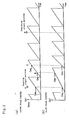
- FIG. 2 is a view further illustrating the operations of the master phase counter Cm1 and the slave phase counter Cs1.
- FIG. 2(a) illustrates operation of the master phase counter Cm1
- FIG. 2(b) illustrates operation of the slave phase counter Cs1.
- the master phase counter Cm1 is cleared with the Z phase pulse Zp of the incremental encoder Pm of the master section, and counts the pulse series Rp in response to the rotation of the incremental encoder Pm. As clarified from this, the master phase counter Cm1 detects the rotation phase of the electric motor of the master section.
- the slave phase counter Cs1 is cleared with the Z phase pulse Zp of the incremental encoder Ps1 of the slave section, and counts the pulse series Rp in response to the rotation from the incremental encoder Ps1 to hereby detect the rotating phase of the electric motor of the slave section.
- Nmax is a pulse number per one revolution of the Z phase-equipped incremental encoders Pm, Ps1, and Covf is a counted value of overflow pulses of the master phase counter Cm1 and the slave phase counter Cs1 which value is added one by one every time the master phase counter Cm1 overflows and is subtracted one by one every time the slave phase counter Cs1 overflows.
- Cm and Cs are count values of the master phase counter Cm1 and the slave phase counter Cs1.
- phase counters Cm1 and Cs1 are operated as illustrated in FIG. 2.
- FIG. 3 is a view illustrating the operation of the origin matching where plural electric motors start their operations from all interrupted state. Once the operation is started, the electric motors of the master section and the electric motors of the slave section are accelerated up to arbitrary rotational frequency with an ordinary rotational frequency instruction.
- FIG. 4 is a view illustrating operation where plural electric motors start their operations from all interruption state and the origin matching is performed during acceleration. Once the operation is started, the contact RYs1 is closed during the acceleration, and a rotational frequency instruction detected by the rotational frequency detector Ss1 is corrected with an output of the phase deviation calculator Hs1, and likewise the origin matching is completed.
- FIG. 5 is a view illustrating the operation of the present embodiment wherein there are electric motors in operation and stopped electric motors among plural electric motors, and the stopped electric motors start their operation to be accelerated up to the rotational frequency of the electric motors in operation, and after completion of the acceleration the origin matching is performed.
- the slave section starting its operation anew is accelerated up to substantially same rotational frequency as that of the section already in operation, and thereafter the origin matching is started at the point A as described previously.
- the origin matching is achieved with the aid of the action of the aforesaid phase deviation Hs, and the origin matching is completed at the point D where the phase deviation Hs becomes 0.
- the concentrated controller C means for electronically generating a rotational frequency signal outputted from the incremental encoder Pm and a signal corresponding to the phase signal as described previously, which concentrated controller C may be operated as the master section.
- signals corresponding to the rotational frequency signal and the phase signal are electronically generated in the concentrated controller C, which signals are in turn provided to the master phase counter Cm1 of the slave section as described in the aforesaid preferred embodiment, whereby the signals corresponding to the rotational frequency signal and the phase signal can be synchronized with the machine shaft of the electric motor of the slave section.
Landscapes
- Engineering & Computer Science (AREA)
- Power Engineering (AREA)
- Control Of Multiple Motors (AREA)
- Control Of Eletrric Generators (AREA)
- Electrophonic Musical Instruments (AREA)
- Selective Calling Equipment (AREA)
Applications Claiming Priority (2)
| Application Number | Priority Date | Filing Date | Title |
|---|---|---|---|
| JP10362567A JP3073727B2 (ja) | 1998-12-21 | 1998-12-21 | 同期制御装置および同期制御方法 |
| JP36256798 | 1998-12-21 |
Publications (3)
| Publication Number | Publication Date |
|---|---|
| EP1014553A2 true EP1014553A2 (de) | 2000-06-28 |
| EP1014553A3 EP1014553A3 (de) | 2001-12-12 |
| EP1014553B1 EP1014553B1 (de) | 2005-08-31 |
Family
ID=18477190
Family Applications (1)
| Application Number | Title | Priority Date | Filing Date |
|---|---|---|---|
| EP99123911A Expired - Lifetime EP1014553B1 (de) | 1998-12-21 | 1999-12-01 | Verfahren und Vorrichtung zur Synchronisierungsregelung |
Country Status (5)
| Country | Link |
|---|---|
| US (2) | US6326747B1 (de) |
| EP (1) | EP1014553B1 (de) |
| JP (1) | JP3073727B2 (de) |
| AT (1) | ATE303670T1 (de) |
| DE (1) | DE69926980T2 (de) |
Cited By (2)
| Publication number | Priority date | Publication date | Assignee | Title |
|---|---|---|---|---|
| EP1150420A1 (de) * | 2000-04-26 | 2001-10-31 | Kabushiki Kaisha Tokyo Kikai Seisakusho | Synchronregelungsvorrichtung |
| EP4368002A4 (de) * | 2021-10-29 | 2024-11-13 | Nanjing Chervon Industry Co., Ltd. | Selbstfahrende arbeitsmaschine und rasenmäher |
Families Citing this family (13)
| Publication number | Priority date | Publication date | Assignee | Title |
|---|---|---|---|---|
| BE1013174A3 (nl) * | 1999-12-10 | 2001-10-02 | Picanol Nv | Werkwijze en aandrijfsysteem voor een machine. |
| DE60215095T2 (de) * | 2001-09-19 | 2007-05-10 | Parker-Hannifin Corp., Cleveland | Motorantrieb und System |
| TWI222268B (en) * | 2003-08-26 | 2004-10-11 | Delta Electronics Inc | Fan system |
| JP4261500B2 (ja) * | 2005-03-04 | 2009-04-30 | ファナック株式会社 | 制御システム |
| US20070162192A1 (en) * | 2006-01-06 | 2007-07-12 | Vincent Russo | Trainer for radio-controlled vehicles |
| EP1886742B1 (de) * | 2006-08-09 | 2009-07-01 | FRATTINI S.p.A.-COSTRUZIONI MECCANICHE | Vorrichtung zum Umformen von Behältern aus Metall mit einer oder mehreren elektronisch gekuppelten Vorrichtungen zum Durchführen einer lokalen oder erweiterten Verformung der Behälter |
| US7402965B2 (en) * | 2006-09-21 | 2008-07-22 | Rockwell Automation Technologies, Inc. | DC common bus self-protection method and system |
| EP3109091B1 (de) * | 2007-09-11 | 2021-11-10 | Hydro-Gear Limited Partnership | Steuerungssysteme und -verfahren für nutzfahrzeuge mit elektrischem antrieb |
| US8207693B2 (en) | 2007-09-11 | 2012-06-26 | Hydro-Gear Limited Partnership | Controller assemblies for electric drive utility vehicles |
| US8907596B2 (en) * | 2012-05-01 | 2014-12-09 | Deere & Company | Method and system for controlling electric motors of a common assembly |
| JP6331225B2 (ja) * | 2015-08-19 | 2018-05-30 | 株式会社安川電機 | モータ制御装置、位置制御システム、及びモータ制御方法 |
| RU2649307C1 (ru) * | 2016-11-18 | 2018-04-02 | Федеральное государственное бюджетное образовательное учреждение высшего образования "Омский государственный технический университет" | Способ фазирования вращающегося вала электродвигателя и устройство для его осуществления |
| US20250301947A1 (en) * | 2024-03-28 | 2025-10-02 | Honda Motor Co., Ltd. | Lawn mower |
Family Cites Families (19)
| Publication number | Priority date | Publication date | Assignee | Title |
|---|---|---|---|---|
| US3644806A (en) * | 1970-03-24 | 1972-02-22 | Honeywell Inc | High-speed printer-paper feed engine |
| US3718846A (en) * | 1971-04-13 | 1973-02-27 | Borg Warner | Variable speed plural motor control system with incremental speed synchronization |
| DE2426532A1 (de) * | 1974-05-31 | 1975-12-04 | Licentia Gmbh | Anordnung zur digitalen, winkelgenauen drehzahlregelung von elektrischen antrieben |
| US4084083A (en) * | 1975-11-05 | 1978-04-11 | Contraves Goerz Corporation | Multi-axis electronic motion generator |
| US4405884A (en) * | 1981-04-27 | 1983-09-20 | Weber Harold J | Shaft position synchronization means for multiple synchronous induction motors |
| JPS5969765A (ja) * | 1982-10-15 | 1984-04-20 | Canon Inc | 回転体駆動装置 |
| JPS59117489A (ja) | 1982-12-23 | 1984-07-06 | Mitsubishi Electric Corp | モ−タ同期回転制御装置 |
| GB2149149A (en) * | 1983-10-28 | 1985-06-05 | Rockwell Graphic Syst | Printing press synchronization |
| US4772966A (en) * | 1984-10-05 | 1988-09-20 | Otari Electric Co., Ltd. | Synchronization method and apparatus |
| JPS62122987A (ja) | 1985-11-15 | 1987-06-04 | 三菱重工業株式会社 | 主機と従機の同期制御装置 |
| JPH01186190A (ja) * | 1988-01-19 | 1989-07-25 | Fuji Electric Co Ltd | 同期制御装置 |
| JP2629784B2 (ja) * | 1988-03-01 | 1997-07-16 | 富士電機株式会社 | 同期制御装置 |
| JP2720584B2 (ja) * | 1990-07-20 | 1998-03-04 | 株式会社安川電機 | サーボシステムの同調位相制御装置 |
| JPH0556684A (ja) | 1991-08-21 | 1993-03-05 | Fuji Electric Co Ltd | モータの追従運転制御装置 |
| JP3372725B2 (ja) * | 1995-08-31 | 2003-02-04 | キヤノン株式会社 | 同期スキャン制御装置 |
| JP3553279B2 (ja) * | 1996-07-12 | 2004-08-11 | 東洋電機製造株式会社 | 同期運転制御方法 |
| JP3580050B2 (ja) | 1996-10-14 | 2004-10-20 | 株式会社明電舎 | 同期制御装置 |
| DE19727824C1 (de) * | 1997-06-30 | 1998-11-19 | Siemens Ag | Verfahren und Vorrichtung zum dezentralen Betrieb bzw. Aufbau einer autarken, winkelgenauen Gleichlaufregelung einzelner Antriebe eines vernetzten Mehrmotorenantriebssystems |
| JP3073730B1 (ja) * | 1999-02-25 | 2000-08-07 | 株式会社東京機械製作所 | 同期制御装置 |
-
1998
- 1998-12-21 JP JP10362567A patent/JP3073727B2/ja not_active Expired - Lifetime
-
1999
- 1999-12-01 DE DE69926980T patent/DE69926980T2/de not_active Expired - Fee Related
- 1999-12-01 EP EP99123911A patent/EP1014553B1/de not_active Expired - Lifetime
- 1999-12-01 AT AT99123911T patent/ATE303670T1/de not_active IP Right Cessation
- 1999-12-16 US US09/464,890 patent/US6326747B1/en not_active Ceased
-
2003
- 2003-11-26 US US10/723,962 patent/USRE40165E1/en not_active Expired - Fee Related
Cited By (2)
| Publication number | Priority date | Publication date | Assignee | Title |
|---|---|---|---|---|
| EP1150420A1 (de) * | 2000-04-26 | 2001-10-31 | Kabushiki Kaisha Tokyo Kikai Seisakusho | Synchronregelungsvorrichtung |
| EP4368002A4 (de) * | 2021-10-29 | 2024-11-13 | Nanjing Chervon Industry Co., Ltd. | Selbstfahrende arbeitsmaschine und rasenmäher |
Also Published As
| Publication number | Publication date |
|---|---|
| JP2000188890A (ja) | 2000-07-04 |
| DE69926980T2 (de) | 2006-07-20 |
| US6326747B1 (en) | 2001-12-04 |
| DE69926980D1 (de) | 2005-10-06 |
| USRE40165E1 (en) | 2008-03-25 |
| EP1014553A3 (de) | 2001-12-12 |
| EP1014553B1 (de) | 2005-08-31 |
| ATE303670T1 (de) | 2005-09-15 |
| JP3073727B2 (ja) | 2000-08-07 |
Similar Documents
| Publication | Publication Date | Title |
|---|---|---|
| EP1014553B1 (de) | Verfahren und Vorrichtung zur Synchronisierungsregelung | |
| JPS6236806B2 (de) | ||
| US4387632A (en) | Control system for synchronizing power presses and associated feed mechanism with interlock features | |
| JP4078065B2 (ja) | 複数のユニットで進行するプロセスを同期化する装置および方法 | |
| EP1032117B1 (de) | Synchronregelungsvorrichtung | |
| JP3580050B2 (ja) | 同期制御装置 | |
| JP4882166B2 (ja) | 位置同期制御装置 | |
| US4492901A (en) | Control system for synchronizing combination press line | |
| JP4638094B2 (ja) | 複数軸制御装置及びその軸間同期方法 | |
| US12222700B2 (en) | Control device | |
| JP2587096B2 (ja) | エンドレスベルトの間欠的駆動装置 | |
| JPH05111282A (ja) | 同期運転駆動装置 | |
| JP4833459B2 (ja) | 複数の機械軸を持つプロセスラインの同期制御方法及び制御装置 | |
| JPS6357333B2 (de) | ||
| JP2629784B2 (ja) | 同期制御装置 | |
| JP2524715B2 (ja) | 数値制御装置の位置決め方法 | |
| JP2932151B2 (ja) | 加工材料供給装置 | |
| SU1080741A3 (ru) | Система автоматического управлени подачей и распределением порций расплавленного стекла в формовочную секционную машину | |
| JP2586175B2 (ja) | 搬送装置の同期運転制御装置 | |
| SU698767A2 (ru) | Устройство дл отбора кирпичей от резательного автомата | |
| JPH0255333B2 (de) | ||
| JPH08290552A (ja) | セクショナルドライブの同期制御方法 | |
| JPH01218378A (ja) | 同期制御装置 | |
| JP2004167548A (ja) | サーボプレス機の制御装置 | |
| KR20110105531A (ko) | 절단기와 리테이너의 연동제어 시스템 및 방법 |
Legal Events
| Date | Code | Title | Description |
|---|---|---|---|
| PUAI | Public reference made under article 153(3) epc to a published international application that has entered the european phase |
Free format text: ORIGINAL CODE: 0009012 |
|
| AK | Designated contracting states |
Kind code of ref document: A2 Designated state(s): AT BE CH CY DE DK ES FI FR GB GR IE IT LI LU MC NL PT SE Kind code of ref document: A2 Designated state(s): AT CH DE GB LI |
|
| AX | Request for extension of the european patent |
Free format text: AL;LT;LV;MK;RO;SI |
|
| PUAL | Search report despatched |
Free format text: ORIGINAL CODE: 0009013 |
|
| AK | Designated contracting states |
Kind code of ref document: A3 Designated state(s): AT BE CH CY DE DK ES FI FR GB GR IE IT LI LU MC NL PT SE |
|
| AX | Request for extension of the european patent |
Free format text: AL;LT;LV;MK;RO;SI |
|
| 17P | Request for examination filed |
Effective date: 20020527 |
|
| AKX | Designation fees paid |
Free format text: AT CH DE GB LI |
|
| 17Q | First examination report despatched |
Effective date: 20021202 |
|
| GRAP | Despatch of communication of intention to grant a patent |
Free format text: ORIGINAL CODE: EPIDOSNIGR1 |
|
| GRAS | Grant fee paid |
Free format text: ORIGINAL CODE: EPIDOSNIGR3 |
|
| GRAA | (expected) grant |
Free format text: ORIGINAL CODE: 0009210 |
|
| AK | Designated contracting states |
Kind code of ref document: B1 Designated state(s): AT CH DE GB LI |
|
| PG25 | Lapsed in a contracting state [announced via postgrant information from national office to epo] |
Ref country code: LI Free format text: LAPSE BECAUSE OF FAILURE TO SUBMIT A TRANSLATION OF THE DESCRIPTION OR TO PAY THE FEE WITHIN THE PRESCRIBED TIME-LIMIT Effective date: 20050831 Ref country code: CH Free format text: LAPSE BECAUSE OF FAILURE TO SUBMIT A TRANSLATION OF THE DESCRIPTION OR TO PAY THE FEE WITHIN THE PRESCRIBED TIME-LIMIT Effective date: 20050831 Ref country code: AT Free format text: LAPSE BECAUSE OF FAILURE TO SUBMIT A TRANSLATION OF THE DESCRIPTION OR TO PAY THE FEE WITHIN THE PRESCRIBED TIME-LIMIT Effective date: 20050831 |
|
| REG | Reference to a national code |
Ref country code: GB Ref legal event code: FG4D Ref country code: CH Ref legal event code: EP |
|
| REF | Corresponds to: |
Ref document number: 69926980 Country of ref document: DE Date of ref document: 20051006 Kind code of ref document: P |
|
| REG | Reference to a national code |
Ref country code: CH Ref legal event code: PL |
|
| PLBE | No opposition filed within time limit |
Free format text: ORIGINAL CODE: 0009261 |
|
| STAA | Information on the status of an ep patent application or granted ep patent |
Free format text: STATUS: NO OPPOSITION FILED WITHIN TIME LIMIT |
|
| 26N | No opposition filed |
Effective date: 20060601 |
|
| PGFP | Annual fee paid to national office [announced via postgrant information from national office to epo] |
Ref country code: DE Payment date: 20081230 Year of fee payment: 10 |
|
| PGFP | Annual fee paid to national office [announced via postgrant information from national office to epo] |
Ref country code: GB Payment date: 20081217 Year of fee payment: 10 |
|
| GBPC | Gb: european patent ceased through non-payment of renewal fee |
Effective date: 20091201 |
|
| PG25 | Lapsed in a contracting state [announced via postgrant information from national office to epo] |
Ref country code: DE Free format text: LAPSE BECAUSE OF NON-PAYMENT OF DUE FEES Effective date: 20100701 |
|
| PG25 | Lapsed in a contracting state [announced via postgrant information from national office to epo] |
Ref country code: GB Free format text: LAPSE BECAUSE OF NON-PAYMENT OF DUE FEES Effective date: 20091201 |