EP1015265B1 - Systeme de suspension de roue et son ressort - Google Patents
Systeme de suspension de roue et son ressort Download PDFInfo
- Publication number
- EP1015265B1 EP1015265B1 EP99931544A EP99931544A EP1015265B1 EP 1015265 B1 EP1015265 B1 EP 1015265B1 EP 99931544 A EP99931544 A EP 99931544A EP 99931544 A EP99931544 A EP 99931544A EP 1015265 B1 EP1015265 B1 EP 1015265B1
- Authority
- EP
- European Patent Office
- Prior art keywords
- coil spring
- spring
- shock absorber
- suspension system
- wheel suspension
- Prior art date
- Legal status (The legal status is an assumption and is not a legal conclusion. Google has not performed a legal analysis and makes no representation as to the accuracy of the status listed.)
- Expired - Lifetime
Links
- 239000000725 suspension Substances 0.000 title claims description 25
- 239000006096 absorbing agent Substances 0.000 claims description 38
- 230000035939 shock Effects 0.000 claims description 38
- 230000006835 compression Effects 0.000 claims description 25
- 238000007906 compression Methods 0.000 claims description 25
- 230000000717 retained effect Effects 0.000 claims description 8
- 230000009471 action Effects 0.000 claims description 3
- 238000004804 winding Methods 0.000 description 9
- 238000000034 method Methods 0.000 description 8
- 230000008569 process Effects 0.000 description 7
- 238000005496 tempering Methods 0.000 description 3
- 238000006243 chemical reaction Methods 0.000 description 2
- 230000007423 decrease Effects 0.000 description 2
- 230000004075 alteration Effects 0.000 description 1
- 238000005266 casting Methods 0.000 description 1
- 230000008859 change Effects 0.000 description 1
- 230000003292 diminished effect Effects 0.000 description 1
- 238000006073 displacement reaction Methods 0.000 description 1
- 238000001746 injection moulding Methods 0.000 description 1
- 238000004519 manufacturing process Methods 0.000 description 1
- 238000007620 mathematical function Methods 0.000 description 1
- 239000000203 mixture Substances 0.000 description 1
- 238000012986 modification Methods 0.000 description 1
- 230000004048 modification Effects 0.000 description 1
Images


Classifications
-
- F—MECHANICAL ENGINEERING; LIGHTING; HEATING; WEAPONS; BLASTING
- F16—ENGINEERING ELEMENTS AND UNITS; GENERAL MEASURES FOR PRODUCING AND MAINTAINING EFFECTIVE FUNCTIONING OF MACHINES OR INSTALLATIONS; THERMAL INSULATION IN GENERAL
- F16F—SPRINGS; SHOCK-ABSORBERS; MEANS FOR DAMPING VIBRATION
- F16F1/00—Springs
- F16F1/02—Springs made of steel or other material having low internal friction; Wound, torsion, leaf, cup, ring or the like springs, the material of the spring not being relevant
- F16F1/04—Wound springs
- F16F1/047—Wound springs characterised by varying pitch
-
- B—PERFORMING OPERATIONS; TRANSPORTING
- B60—VEHICLES IN GENERAL
- B60G—VEHICLE SUSPENSION ARRANGEMENTS
- B60G15/00—Resilient suspensions characterised by arrangement, location or type of combined spring and vibration damper, e.g. telescopic type
- B60G15/02—Resilient suspensions characterised by arrangement, location or type of combined spring and vibration damper, e.g. telescopic type having mechanical spring
- B60G15/06—Resilient suspensions characterised by arrangement, location or type of combined spring and vibration damper, e.g. telescopic type having mechanical spring and fluid damper
- B60G15/07—Resilient suspensions characterised by arrangement, location or type of combined spring and vibration damper, e.g. telescopic type having mechanical spring and fluid damper the damper being connected to the stub axle and the spring being arranged around the damper
-
- B—PERFORMING OPERATIONS; TRANSPORTING
- B60—VEHICLES IN GENERAL
- B60G—VEHICLE SUSPENSION ARRANGEMENTS
- B60G2200/00—Indexing codes relating to suspension types
- B60G2200/10—Independent suspensions
- B60G2200/17—Independent suspensions with a strut contributing to the suspension geometry by being articulated onto the wheel support
-
- B—PERFORMING OPERATIONS; TRANSPORTING
- B60—VEHICLES IN GENERAL
- B60G—VEHICLE SUSPENSION ARRANGEMENTS
- B60G2202/00—Indexing codes relating to the type of spring, damper or actuator
- B60G2202/10—Type of spring
- B60G2202/12—Wound spring
-
- B—PERFORMING OPERATIONS; TRANSPORTING
- B60—VEHICLES IN GENERAL
- B60G—VEHICLE SUSPENSION ARRANGEMENTS
- B60G2202/00—Indexing codes relating to the type of spring, damper or actuator
- B60G2202/30—Spring/Damper and/or actuator Units
- B60G2202/31—Spring/Damper and/or actuator Units with the spring arranged around the damper, e.g. MacPherson strut
- B60G2202/312—The spring being a wound spring
-
- B—PERFORMING OPERATIONS; TRANSPORTING
- B60—VEHICLES IN GENERAL
- B60G—VEHICLE SUSPENSION ARRANGEMENTS
- B60G2204/00—Indexing codes related to suspensions per se or to auxiliary parts
- B60G2204/10—Mounting of suspension elements
- B60G2204/12—Mounting of springs or dampers
- B60G2204/124—Mounting of coil springs
- B60G2204/1242—Mounting of coil springs on a damper, e.g. MacPerson strut
-
- B—PERFORMING OPERATIONS; TRANSPORTING
- B60—VEHICLES IN GENERAL
- B60G—VEHICLE SUSPENSION ARRANGEMENTS
- B60G2206/00—Indexing codes related to the manufacturing of suspensions: constructional features, the materials used, procedures or tools
- B60G2206/01—Constructional features of suspension elements, e.g. arms, dampers, springs
- B60G2206/40—Constructional features of dampers and/or springs
- B60G2206/42—Springs
- B60G2206/426—Coil springs having a particular shape, e.g. curved axis, pig-tail end coils
Definitions
- the present invention relates to a wheel suspension system. More particularly, the present invention relates to a wheel suspension system which is characterized by a novel spring structure and a novel spring mounting arrangement, and a spring for such a wheel suspension system.
- a vehicle body and a link member of the wheel suspension system are connected to each other by an assembly including a tubular shock absorber consisting of a cylinder filled with oil and a piston received therein, and a compression coil spring surrounding the shock absorber.
- a tubular shock absorber consisting of a cylinder filled with oil and a piston received therein
- a compression coil spring surrounding the shock absorber.
- a helical spring which is coiled in the untensioned state with transverse relative displacement of the turns so that it has the form of a skewed cylinder when seen in cross-section.
- the coil spring in its unstressed state has a skewed or oblique cylindrical shape, and is forced into a true cylindrical shape in its assembled state.
- GB-A-1 031 650 discloses mutually offset spring seats which retain a normal cylindrical spring in an oblique shape. This again requires a laterally pre-stressing of the spring for assembly.
- a wheel suspension system having a helical spring, whose wire diameter varies in at least one winding turn between a minimum value, a maximum value and again the minimum value to produce lateral forces and moments providing a spring force line of action which is not coincident with the spring center line.
- a primary object of the present invention is to provide a vehicle wheel suspension system comprising a tubular shock absorber, and a compression coil spring surrounding the shock absorber which can favorably reduce the sliding resistance that may be produced between the cylinder and the piston of the shock absorber without increasing the size of the system.
- a second object of the present invention is to provide a vehicle wheel suspension system which can favorably reduce the sliding resistance that may be produced between the cylinder and the piston of the shock absorber, and can thereby improve the ride comfort of the vehicle and the durability of the shock absorber.
- a third object of the present invention is to provide a vehicle wheel suspension system which can favorably reduce the sliding resistance that may be produced between the cylinder and the piston of the shock absorber without increasing the size of the system and without complicating the assembly work.
- a fourth object of the present invention is to provide coil springs which are suitable for use in such vehicle wheel suspension systems.
- a vehicle wheel suspension system comprising a tubular shock absorber, and a compression coil spring surrounding the shock absorber, characterized in that the compression coil spring consists of a coil spring which is wound around a true cylinder so as to have a cyclically varying pitch angle between a single local minimum and a single local maximum for each turn, and retained so as to be extended and compressed along an upright axial line so as to produce lateral forces between two ends thereof as the compression coil spring is extended and compressed.
- the lateral forces which are produced between the two ends are determined such that lateral forces which are produced between a piston and a cylinder of the shock absorber due to an offset between the line of action from a wheel and an axial line of the shock absorber may be minimized.
- the sliding resistance due to the lateral force acting between the cylinder and piston of the shock absorber can be favorably reduced so that the ride comfort of the vehicle and the durability of the shock absorber can be both improved.
- the compression coil spring can be adapted to produce the required lateral forces between the two ends thereof as it is compressed and extended without increasing the size of the system and without suffering from geometrical restrictions if the compression coil spring consists of a coil spring which is wound around an oblique cylinder, and retained so as to have an upright axial line by applying a lateral initial load thereto, and to be extended and compressed along the upright axial line.
- a compression coil spring which is wound around a true cylinder so as to have a cyclically varying pitch angle, characterized in that the pitch angle varies between a single local minimum, and a single local maximum for each turn so as to produce lateral forces between two ends of the spring as it is extended and compressed.
- FIG. 1 is a simplified fragmentary, partly broken away front view of an essential part of a vehicle wheel suspension system.
- a strut assembly 4 having an upper end pivotally attached to a vehicle body 1 and a lower end pivotally attached to a link member 3 connecting a wheel carrier 2 to the vehicle body 1, comprises a shock absorber 5 consisting of a tubular oil damper, and a compression coil spring 6 retained by spring seats 7 and 8 between the cylinder and the piston of the shock absorber 5.
- the upper spring seat 7 is, jointly with the upper end of the piston rod of the shock absorber 5, pivotally attached to the vehicle body 1 via a rubber busing or the like, and the lower spring seat 8 is fixedly attached to the outer periphery of the cylinder of the shock absorber 5.
- the compression coil spring 6 has a central axial line B which is tilted by an angle ⁇ under no load condition as indicated by the imaginary lines in Figure 2.
- This compression coil spring 6 can be deformed into a shape having a vertical axial line A of a normal compression coil spring by resiliently deforming this coil spring 6 by firmly retaining the two ends thereof, and applying laterally opposing forces of a prescribed magnitude to the two ends.
- this compression coil spring 6 can be considered as being obtained by tilting the vertical axial line A of a normal cylindrical coil spring, which is considered as having a reference shape, and obtained by applying the laterally opposing forces, to a tilted axial line B by an angle ⁇ .
- the corresponding point on the compression coil spring having the tilted axial line B can be given by maintaining the Y coordinate or Sny and shifting the X coordinate by the product of the Y coordinate Sny and tan ⁇ with respect to the reference coordinate (Snx, Sny), or by the coordinate (Snx + Sny ⁇ tan ⁇ , Sny).
- the tilt angle ⁇ of the central line B of the coil spring 6 is determined by the lateral load that is applied between the cylinder and the piston of the shock absorber 5 of the vehicle.
- the two ends of the coil spring 6 are required to be retained with initial lateral forces and moments applied thereto, and the spring seats should be adapted to meet such requirements.
- Such a coil spring 6 can be manufactured by winding a coil wire around an oblique cylindrical die while feeding the coil wire at a constant pitch with respect to the reference vertical axial line.
- the outer circumferential surface of the die may be either smooth or provided with a helical groove for guiding the coil wire.
- Such a coil process is typically conducted as a hot forming process, and the tempering and other processes are conducted thereafter.
- the reaction force N is given by a mathematical function of the lateral load vector R sus which is applied between the cylinder and the piston of the shock absorber 5.
- the lateral load vector R sus is in turn given by the following equation.
- Rsus Rgeo + Rcoil
- R geo is a geometrical lateral load vector which is geometrically determined by the difference in the directions of motion of the axle and the shock absorber in the particular wheel suspension system
- R coil is the lateral load due to the tilt angle of the coil spring. Because the sliding resistance F is reduced when the lateral load vector R sus is reduced, the direction and magnitude of R coil should be selected so as to cancel Rgeo. Provided that other conditions are identical, the larger the tilt angle of the central line B is, the larger Rcoil becomes. Such a relation may be analytically determined. However, in practice, a finite element method may be used for determining the required relationship so that the coil may be wound according to an optimum design which best suits the particular application.
- the coil spring 6 was tilted two-dimensionally, but may also be tilted three-dimensionally depending on R geo.
- the coil spring may also have a curved axial line under no load condition.
- the coil spring may also have a nonlinear spring constant which changes in dependence on the deflection of the coil spring.
- a normal cylindrical coil spring 16 having a vertical axial line C under the rest condition as indicated by the imaginary lines in Figure 4 is also possible to use as a second embodiment of the present invention, in place of the spring 6 having the tilted axial line B under the rest condition.
- the two ends of the cylindrical coil spring 16 are firmly retained, and are subjected to lateral forces so as to tilt the axial line of the coil spring by an angle ⁇ as indicated by the tilted axial line D during use.
- the coil spring 16 is compressed and extended along the axial line D.
- the two ends of the coil spring 16 are required to be retained with initial lateral forces and moments applied thereto, and the spring seats should be adapted to meet such requirements.
- Such a coil spring 16 can be manufactured by winding a coil wire fed from a feeder around a rotating cylindrical die of a coiling machine, much like winding a normal cylindrical coil spring. Such a coil process is typically conducted as a hot forming process, and the tempering and other processes are conducted thereafter. Likewise, the outer circumferential surface of the die may be either smooth or provided with a helical groove for guiding the coil wire.
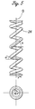
- FIGs 5 to 7 show a spring of the present invention.
- This compression coil spring 26 has a substantially true cylindrical shape as illustrated in Figure 5 in its unstressed state.
- This consists of a constant-pitch cylindrical coil spring which has a constant radius r and a constant pitch P, and its axial line O is straight under no load condition.
- the pitch angle ( ⁇ ) changes cyclically for each turn.
- the pitch angle ( ⁇ ) is given as an increment ( ⁇ H) of the spring height (H) for a given increment (r ⁇ ) of a length (r ⁇ ) of the coil wire.
- ⁇ denotes the angle of a point of the coil wire with respect to the central axial line in the winding direction.
- Such a coil spring 26 can be manufactured by winding a coil wire fed from a feeding unit around a rotating cylindrical die in a normal way except for that the axial feed speed of the feed unit is not uniform but varied according to the rotational angle of the cylindrical die or the phase angle thereof. Thereafter, the tempering and other processes are conducted.
- the outer circumferential surface of the die may be either smooth or provided with a helical groove for guiding the coil wire.
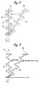
- Figure 6 shows a graph in which the ordinate corresponds to the number of nodes which are defined along the length of the coil wire at the rate of 20 nodes per turn of the coil wire, and the abscissa corresponds to the height (H) of each point on the coil wire.
- the height (H) of each point on the coil wire increases in proportion to the number of nodes or the angle ( ⁇ ) of the nodal point on the coil wire in the winding direction.
- the height (H) cyclically increases and decreases with respect to the level of the broken line B in relation with the number of nodes or the angle ( ⁇ ) of the nodal point on the coil wire.
- the nodal points are similarly defined, and the ordinate corresponds to the number of nodes while the abscissa corresponds to the pitch angle ( ⁇ ) of the corresponding point on the coil wire.
- the pitch angle ( ⁇ ) of the coil spring alternates between a local maximum and a local minimum for each 180 degrees in relation with the number of nodes or the angle ( ⁇ ) of the nodal point on the coil wire as indicated by the solid line A. More specifically, there is a peak and a dip of the pitch angle ( ⁇ ) for each turn of the coil (which includes 20 nodal points in the illustrated embodiment).
- the lateral forces that are produced at the two ends of the coil spring 26 become larger as the amplitude (W in Figure 7) of the pitch angle ( ⁇ ) gets larger. This amplitude should be decided according to the lateral forces which may be produced between the cylinder and the piston.
- the geometrical structure of this coil spring 26 is similar to that of the coil spring 6 illustrated in Figure 4 except for the arrangement of the coil ends.
- the reference seat surface of each coil end of the coil spring 6 illustrated in Figure 5 is perpendicular to the direction of compressing the coil spring whereas the reference seat surface of each coil end of the coil spring 16 illustrated in Figure 4 is perpendicular to the direction of constant pitch (A) of the spiral curve of the coil wire, and is inclined by the angle ( ⁇ ) with respect to the central axial line of the coil spring.
- the pitch angle ( ⁇ ) changed cyclically between a local minimum and a local maximum for each 180 degrees, but the local minima and maxima may repeat at two points on each turn which is angularly offset from a diameterical line and, for instance, angularly spaced apart by 160 degrees as long as the angular positions of the local minima and maxima in each turn are fixed.
- FIG 7 shows the relationship between the nodes or the angle ( ⁇ ) in the winding direction and the pitch angle ( ⁇ ) of conical springs, as well as those of the cylindrical coil spring having a cyclically varying pitch angle as shown in Figure 5 (solid line A) and a normal constant pitch angle cylindrical coil spring (broken line B).
- solid line A solid line A
- broken line B normal constant pitch angle cylindrical coil spring
- a conical spring having a cyclically varying pitch angle its properties may be given as a composition of those given by the solid line A and broken line C or the pitch angle may cyclically increase and decrease, while the amplitude of the variation in the pitch angle gradually increases, with the increase in the number of nodes or in the increase in the angle ( ⁇ ) in the winding direction as shown in Fig 7. by double-dot chain-dot line D.
- the vehicle wheel suspension system of the present invention in a wheel suspension system comprising a tubular shock absorber and a compression coil spring surrounding the shock absorber which are connected between a vehicle body and a wheel, the spring is adapted to produce lateral forces which oppose the lateral forces that are produced in the shock absorber as the coil spring is compressed. Therefore, the sliding resistance between the cylinder and the piston due to the lateral load produced in the shock absorber can be reduced or totally eliminated without increasing the size of the suspension system.
Landscapes
- Engineering & Computer Science (AREA)
- Mechanical Engineering (AREA)
- General Engineering & Computer Science (AREA)
- Vehicle Body Suspensions (AREA)
- Springs (AREA)
- Fluid-Damping Devices (AREA)
Claims (5)
- Système de suspension de roue de véhicule comprenant un amortisseur de chocs tubulaire et un ressort de compression hélicoïdal entourant l'amortisseur de chocs, caractérisé en ce que le ressort de compression hélicoïdal (26) se compose d'un ressort hélicoïdal qui est enroulé autour d'un cylindre d'aplomb de manière à avoir un angle de pas qui varie de manière cyclique (α) entre un minimum local unique et un maximum local unique à chaque révolution, et maintenu de manière à se détendre et se comprimer le long d'une ligne axiale rectiligne (O) afin de produire des forces latérales entre ses deux extrémités alors que le ressort de compression hélicoïdal (26) s'étend et se comprime.
- Système de suspension de roue de véhicule selon la revendication 1, caractérisé en ce que les forces latérales qui sont produites entre les deux extrémités sont déterminées de telle sorte que les forces latérales qui sont produites entre un piston et un cylindre de l'amortisseur de chocs en raison d'un décalage entre la ligne d'action d'une roue et une ligne axiale de l'amortisseur de chocs puissent être minimisées.
- Système de suspension de roue de véhicule selon la revendication 1, caractérisé en ce que le ressort de compression (26) a une forme cylindrique sensiblement d'aplomb lorsqu'il est à l'état non contraint.
- Ressort de compression hélicoïdal (26) qui est enroulé autour d'un cylindre d'aplomb de manière à présenter un angle de pas qui varie de manière cyclique (α), caractérisé en ce que l'angle de pas (α) varie entre un minimum local unique et un maximum local unique à chaque révolution, de manière à produire des forces latérales entre deux extrémités du ressort alors qu'il se détend et se comprime.
- Ressort de compression hélicoïdal selon la revendication 4, caractérisé en ce que le ressort de compression (26) a une forme cylindrique sensiblement d'aplomb lorsqu'il est à l'état non contraint.
Applications Claiming Priority (5)
| Application Number | Priority Date | Filing Date | Title |
|---|---|---|---|
| JP21047898 | 1998-07-27 | ||
| JP21047898 | 1998-07-27 | ||
| JP1167899 | 1999-01-20 | ||
| JP1167899 | 1999-01-20 | ||
| PCT/JP1999/003999 WO2000006401A1 (fr) | 1998-07-27 | 1999-07-27 | Systeme de suspension de roue et son ressort |
Publications (3)
| Publication Number | Publication Date |
|---|---|
| EP1015265A1 EP1015265A1 (fr) | 2000-07-05 |
| EP1015265B1 true EP1015265B1 (fr) | 2003-02-26 |
| EP1015265B2 EP1015265B2 (fr) | 2010-08-04 |
Family
ID=26347153
Family Applications (1)
| Application Number | Title | Priority Date | Filing Date |
|---|---|---|---|
| EP99931544A Expired - Lifetime EP1015265B2 (fr) | 1998-07-27 | 1999-07-27 | Systeme de suspension de roue et son ressort |
Country Status (8)
| Country | Link |
|---|---|
| US (1) | US6460835B1 (fr) |
| EP (1) | EP1015265B2 (fr) |
| JP (1) | JP3515957B2 (fr) |
| AU (1) | AU4801499A (fr) |
| BR (1) | BR9906649A (fr) |
| DE (1) | DE69905548T3 (fr) |
| ES (1) | ES2191441T5 (fr) |
| WO (1) | WO2000006401A1 (fr) |
Families Citing this family (19)
| Publication number | Priority date | Publication date | Assignee | Title |
|---|---|---|---|---|
| JP2002178736A (ja) * | 2000-12-14 | 2002-06-26 | Chuo Spring Co Ltd | 自動車用懸架コイルばね及び該懸架コイルばねを備えたストラット型懸架装置 |
| ATE457884T1 (de) | 2001-04-13 | 2010-03-15 | Mitsubishi Steel Mfg | Aufhängungsschraubenfeder |
| JP2004003908A (ja) * | 2002-06-03 | 2004-01-08 | Matsushita Electric Ind Co Ltd | 荷重センサ |
| FR2860753B1 (fr) * | 2003-10-09 | 2007-07-27 | Allevard Rejna Autosuspensions | Suspension de vehicule |
| JP2005226673A (ja) * | 2004-02-10 | 2005-08-25 | Nhk Spring Co Ltd | コイルばね及び懸架装置 |
| CN101907144A (zh) * | 2009-06-05 | 2010-12-08 | 中国第一汽车集团公司 | 一种连续变刚度悬架螺旋弹簧 |
| EP2719480A4 (fr) * | 2011-06-06 | 2015-03-11 | Gestarsic S L | Ressort pour amortissement directionnel, procédé et dispositif de fabrication de celui-ci |
| DE102014201632B4 (de) | 2013-03-07 | 2021-09-02 | Ford Global Technologies, Llc | Seitlich neigbares, mehrspuriges Fahrzeug |
| DE102014201630B4 (de) * | 2013-03-07 | 2021-09-02 | Ford Global Technologies, Llc | Seitlich neigbares, mehrspuriges Fahrzeug |
| DE102014217246B3 (de) | 2014-08-29 | 2015-12-24 | Ford Global Technologies, Llc | Stabilisierungsanordnung für ein Neigefahrwerk eines Fahrzeugs |
| DE102014217386B4 (de) | 2014-09-01 | 2024-11-14 | Ford Global Technologies, Llc | Verfahren zum Betrieb eines Neigefahrwerks für ein schienenungebundenes Fahrzeug |
| US10076939B2 (en) | 2014-11-26 | 2018-09-18 | Ford Global Technologies, Llc | Suspension systems for laterally tiltable multitrack vehicles |
| US10023019B2 (en) | 2015-02-24 | 2018-07-17 | Ford Global Technologies, Llc | Rear suspension systems with rotary devices for laterally tiltable multitrack vehicles |
| US9925843B2 (en) | 2015-02-24 | 2018-03-27 | Ford Global Technologies, Llc | Rear suspension systems for laterally tiltable multitrack vehicles |
| DE102015210850A1 (de) * | 2015-06-12 | 2016-12-15 | Ford Global Technologies, Llc | Radaufhängung für ein Kraftfahrzeug |
| DE102015211180B4 (de) * | 2015-06-18 | 2024-08-08 | Ford Global Technologies, Llc | Radaufhängung für ein Kraftfahrzeug |
| JP6613095B2 (ja) | 2015-10-01 | 2019-11-27 | 日本発條株式会社 | 懸架用コイルばね |
| JP6367257B2 (ja) * | 2016-04-13 | 2018-08-01 | サンコール株式会社 | コイルばね |
| US10065471B2 (en) * | 2017-01-31 | 2018-09-04 | Nhk Spring Co., Ltd. | Coil spring for vehicle suspension |
Family Cites Families (22)
| Publication number | Priority date | Publication date | Assignee | Title |
|---|---|---|---|---|
| US210027A (en) * | 1878-11-19 | Improvement in gar-springs | ||
| US2643109A (en) * | 1945-05-28 | 1953-06-23 | Gen Spring Corp | Spring device |
| DE1430586A1 (de) | 1964-02-27 | 1969-03-13 | Bayerische Motoren Werke Ag | Geradfuehrung fuer unabhaengig aufgehaengte Raeder von Kraftfahrzeugen |
| GB1031650A (en) | 1965-04-29 | 1966-06-02 | Ford Motor Co | Macpherson strut-type independent wheel suspension |
| DE1505616A1 (de) | 1966-07-22 | 1970-07-23 | Bayerische Motoren Werke Ag | Vorrichtung zur Geradfuehrung von unabhaengig aufgehaengten Raedern von Kraftfahrzeugen |
| DE1505615A1 (de) | 1966-07-22 | 1970-09-24 | Bayerische Motoren Werke Ag | Vorrichtung zur Geradfuehrung von unabhaengig aufgehaengten Raedern von Kraftfahrzeugen |
| DE6935759U (de) | 1969-09-10 | 1969-12-11 | Standard Elektrik Lorenz Ag | Schraubenfeder |
| DE7024634U (de) † | 1970-07-01 | 1970-11-26 | Opel A Ag | Kraftfahrzeug mit Einzelradaufhängevorriehtung.Anm: Adam Opel AG, 6090 Rüsselsheim |
| DE3307543C2 (de) * | 1983-03-03 | 1985-04-11 | Daimler-Benz Ag, 7000 Stuttgart | Radaufhängung für angetriebene Räder von Kraftfahrzeugen |
| NL8402144A (nl) * | 1984-07-06 | 1986-02-03 | Philips Nv | Platenspeler met een liftinrichting voor de toonarm. |
| JPS6228534A (ja) | 1985-07-30 | 1987-02-06 | Hitachi Metals Ltd | コイルばね |
| DE3743451A1 (de) | 1987-12-08 | 1989-06-29 | Muhr & Bender | Radaufhaengung |
| DE3743450A1 (de) | 1987-12-08 | 1989-06-29 | Muhr & Bender | Radaufhaengung |
| DE3900473A1 (de) | 1989-01-10 | 1990-07-26 | Theodor Schroeder Federnfabrik | Schraubendruckfeder |
| DE4021314A1 (de) * | 1989-11-02 | 1991-05-08 | Bilstein August Gmbh Co Kg | Federbein fuer ein kraftfahrzeug |
| DE4124326C1 (fr) † | 1991-07-23 | 1992-04-16 | Krupp Brueninghaus Gmbh, 5980 Werdohl, De | |
| JP2551289Y2 (ja) | 1991-08-06 | 1997-10-22 | 株式会社松尾製作所 | 偏荷重性コイルスプリング |
| DE4331366A1 (de) | 1993-09-15 | 1995-03-16 | Bayerische Motoren Werke Ag | Fahrzeug-Radaufhängung |
| US5454150A (en) † | 1993-11-10 | 1995-10-03 | The United States Of America As Represented By The Administrator Of The National Aeronautics And Space Administration | Manufacturing methods for machining spring ends parallel at loaded length |
| JP3960710B2 (ja) | 1998-07-31 | 2007-08-15 | 中央発條株式会社 | 自動車用懸架コイルばね |
| JP4162804B2 (ja) * | 1998-07-31 | 2008-10-08 | 中央発條株式会社 | ストラット型懸架装置 |
| US6155544A (en) * | 1998-10-09 | 2000-12-05 | Chrysler Corporation | Vehicle shock absorber and strut damper spring seat pad having a discontinuous spring seat surface |
-
1999
- 1999-07-27 BR BR9906649-1A patent/BR9906649A/pt not_active IP Right Cessation
- 1999-07-27 EP EP99931544A patent/EP1015265B2/fr not_active Expired - Lifetime
- 1999-07-27 DE DE69905548T patent/DE69905548T3/de not_active Expired - Lifetime
- 1999-07-27 AU AU48014/99A patent/AU4801499A/en not_active Abandoned
- 1999-07-27 ES ES99931544T patent/ES2191441T5/es not_active Expired - Lifetime
- 1999-07-27 JP JP2000562229A patent/JP3515957B2/ja not_active Expired - Lifetime
- 1999-07-27 WO PCT/JP1999/003999 patent/WO2000006401A1/fr not_active Ceased
- 1999-07-27 US US09/509,289 patent/US6460835B1/en not_active Expired - Lifetime
Also Published As
| Publication number | Publication date |
|---|---|
| ES2191441T3 (es) | 2003-09-01 |
| EP1015265A1 (fr) | 2000-07-05 |
| WO2000006401A1 (fr) | 2000-02-10 |
| DE69905548T2 (de) | 2003-11-20 |
| BR9906649A (pt) | 2000-08-29 |
| JP2002521266A (ja) | 2002-07-16 |
| ES2191441T5 (es) | 2011-01-20 |
| EP1015265B2 (fr) | 2010-08-04 |
| AU4801499A (en) | 2000-02-21 |
| US6460835B1 (en) | 2002-10-08 |
| JP3515957B2 (ja) | 2004-04-05 |
| DE69905548D1 (de) | 2003-04-03 |
| DE69905548T3 (de) | 2011-03-17 |
Similar Documents
| Publication | Publication Date | Title |
|---|---|---|
| EP1015265B1 (fr) | Systeme de suspension de roue et son ressort | |
| EP0225271B1 (fr) | Suspension pneumatique à compensation des forces latérales | |
| EP1120580B2 (fr) | Ressort de compression hélicoidal incurvé | |
| US5154263A (en) | Method and apparatus for controlling the flow of damping fluid through a piston | |
| EP0976590B1 (fr) | Ressort de compression hélicoidal pour une suspension de véhicule | |
| US5288101A (en) | Variable rate torsion control system for vehicle suspension | |
| US6328294B1 (en) | Elastomeric spring system | |
| US6481701B2 (en) | Spring having coils of varying diameters | |
| EP1215059B1 (fr) | Ressort de compression hélicoidal pour une suspension de véhicule | |
| EP1231402B1 (fr) | Ressort de compression hélicoidal pour une suspension de véhicule | |
| US6726191B2 (en) | Spring sheet | |
| US6364297B1 (en) | Torsion bar anchor | |
| JP2005226673A (ja) | コイルばね及び懸架装置 | |
| JP3938766B2 (ja) | 圧縮コイルばね | |
| CN118375680A (zh) | 合成橡胶衬套 | |
| JP2017067237A (ja) | 懸架用コイルばね | |
| CN106256569B (zh) | 用于机动车辆的车轮悬架 | |
| JP3042371B2 (ja) | 圧縮コイルばね | |
| KR100616010B1 (ko) | 차량의 스트럿어셈블리 | |
| US6024342A (en) | Suspension spring | |
| EP4116117A1 (fr) | Ressort hélicoïdal amélioré pour système de suspension de véhicule | |
| JPH06270642A (ja) | 自動車用スタビライザ | |
| JPH07132722A (ja) | 懸架ばね機構 | |
| JPS5833122B2 (ja) | 車両用スタビライザ装置 |
Legal Events
| Date | Code | Title | Description |
|---|---|---|---|
| PUAI | Public reference made under article 153(3) epc to a published international application that has entered the european phase |
Free format text: ORIGINAL CODE: 0009012 |
|
| AK | Designated contracting states |
Kind code of ref document: A1 Designated state(s): AT BE CH CY DE DK ES FI FR GB GR IE IT LI LU MC NL PT SE |
|
| 17P | Request for examination filed |
Effective date: 20000519 |
|
| 17Q | First examination report despatched |
Effective date: 20010924 |
|
| GRAG | Despatch of communication of intention to grant |
Free format text: ORIGINAL CODE: EPIDOS AGRA |
|
| GRAG | Despatch of communication of intention to grant |
Free format text: ORIGINAL CODE: EPIDOS AGRA |
|
| GRAG | Despatch of communication of intention to grant |
Free format text: ORIGINAL CODE: EPIDOS AGRA |
|
| GRAH | Despatch of communication of intention to grant a patent |
Free format text: ORIGINAL CODE: EPIDOS IGRA |
|
| GRAH | Despatch of communication of intention to grant a patent |
Free format text: ORIGINAL CODE: EPIDOS IGRA |
|
| GRAA | (expected) grant |
Free format text: ORIGINAL CODE: 0009210 |
|
| AK | Designated contracting states |
Designated state(s): DE ES FR GB IT |
|
| REG | Reference to a national code |
Ref country code: GB Ref legal event code: FG4D |
|
| REG | Reference to a national code |
Ref country code: IE Ref legal event code: FG4D |
|
| REF | Corresponds to: |
Ref document number: 69905548 Country of ref document: DE Date of ref document: 20030403 Kind code of ref document: P |
|
| ET | Fr: translation filed | ||
| REG | Reference to a national code |
Ref country code: ES Ref legal event code: FG2A Ref document number: 2191441 Country of ref document: ES Kind code of ref document: T3 |
|
| PLBQ | Unpublished change to opponent data |
Free format text: ORIGINAL CODE: EPIDOS OPPO |
|
| PLBI | Opposition filed |
Free format text: ORIGINAL CODE: 0009260 |
|
| PLBQ | Unpublished change to opponent data |
Free format text: ORIGINAL CODE: EPIDOS OPPO |
|
| PLBI | Opposition filed |
Free format text: ORIGINAL CODE: 0009260 |
|
| 26 | Opposition filed |
Opponent name: MUHR UND BENDER KG Effective date: 20031126 Opponent name: VERBAND DER DEUTSCHEN FEDERNINDUSTRIE Effective date: 20031123 |
|
| 26 | Opposition filed |
Opponent name: KLUNKER, HANS-FRIEDRICH, DR. Effective date: 20031125 Opponent name: MUHR UND BENDER KG Effective date: 20031126 Opponent name: VERBAND DER DEUTSCHEN FEDERNINDUSTRIE Effective date: 20031123 |
|
| PLAX | Notice of opposition and request to file observation + time limit sent |
Free format text: ORIGINAL CODE: EPIDOSNOBS2 |
|
| PLAX | Notice of opposition and request to file observation + time limit sent |
Free format text: ORIGINAL CODE: EPIDOSNOBS2 |
|
| PLBB | Reply of patent proprietor to notice(s) of opposition received |
Free format text: ORIGINAL CODE: EPIDOSNOBS3 |
|
| PLAB | Opposition data, opponent's data or that of the opponent's representative modified |
Free format text: ORIGINAL CODE: 0009299OPPO |
|
| R26 | Opposition filed (corrected) |
Opponent name: KLUNKER, HANS-FRIEDRICH, DR. Effective date: 20031125 Opponent name: MUHR UND BENDER KG Effective date: 20031126 Opponent name: VERBAND DER DEUTSCHEN FEDERNINDUSTRIE Effective date: 20031123 |
|
| RDAF | Communication despatched that patent is revoked |
Free format text: ORIGINAL CODE: EPIDOSNREV1 |
|
| PLBP | Opposition withdrawn |
Free format text: ORIGINAL CODE: 0009264 |
|
| APAH | Appeal reference modified |
Free format text: ORIGINAL CODE: EPIDOSCREFNO |
|
| APBP | Date of receipt of notice of appeal recorded |
Free format text: ORIGINAL CODE: EPIDOSNNOA2O |
|
| APBQ | Date of receipt of statement of grounds of appeal recorded |
Free format text: ORIGINAL CODE: EPIDOSNNOA3O |
|
| APBU | Appeal procedure closed |
Free format text: ORIGINAL CODE: EPIDOSNNOA9O |
|
| PUAH | Patent maintained in amended form |
Free format text: ORIGINAL CODE: 0009272 |
|
| STAA | Information on the status of an ep patent application or granted ep patent |
Free format text: STATUS: PATENT MAINTAINED AS AMENDED |
|
| 27A | Patent maintained in amended form |
Effective date: 20100804 |
|
| AK | Designated contracting states |
Kind code of ref document: B2 Designated state(s): DE ES FR GB IT |
|
| REG | Reference to a national code |
Ref country code: ES Ref legal event code: DC2A Effective date: 20110110 |
|
| REG | Reference to a national code |
Ref country code: FR Ref legal event code: PLFP Year of fee payment: 18 |
|
| REG | Reference to a national code |
Ref country code: FR Ref legal event code: PLFP Year of fee payment: 19 |
|
| REG | Reference to a national code |
Ref country code: FR Ref legal event code: PLFP Year of fee payment: 20 |
|
| PGFP | Annual fee paid to national office [announced via postgrant information from national office to epo] |
Ref country code: FR Payment date: 20180612 Year of fee payment: 20 |
|
| PGFP | Annual fee paid to national office [announced via postgrant information from national office to epo] |
Ref country code: IT Payment date: 20180713 Year of fee payment: 20 Ref country code: DE Payment date: 20180717 Year of fee payment: 20 Ref country code: ES Payment date: 20180802 Year of fee payment: 20 |
|
| PGFP | Annual fee paid to national office [announced via postgrant information from national office to epo] |
Ref country code: GB Payment date: 20180725 Year of fee payment: 20 |
|
| REG | Reference to a national code |
Ref country code: DE Ref legal event code: R071 Ref document number: 69905548 Country of ref document: DE |
|
| REG | Reference to a national code |
Ref country code: GB Ref legal event code: PE20 Expiry date: 20190726 |
|
| PG25 | Lapsed in a contracting state [announced via postgrant information from national office to epo] |
Ref country code: GB Free format text: LAPSE BECAUSE OF EXPIRATION OF PROTECTION Effective date: 20190726 |
|
| REG | Reference to a national code |
Ref country code: ES Ref legal event code: FD2A Effective date: 20200803 |
|
| PG25 | Lapsed in a contracting state [announced via postgrant information from national office to epo] |
Ref country code: ES Free format text: LAPSE BECAUSE OF EXPIRATION OF PROTECTION Effective date: 20190728 |