EP1015836B1 - Wärmesenke mit sockel - Google Patents
Wärmesenke mit sockel Download PDFInfo
- Publication number
- EP1015836B1 EP1015836B1 EP98937980A EP98937980A EP1015836B1 EP 1015836 B1 EP1015836 B1 EP 1015836B1 EP 98937980 A EP98937980 A EP 98937980A EP 98937980 A EP98937980 A EP 98937980A EP 1015836 B1 EP1015836 B1 EP 1015836B1
- Authority
- EP
- European Patent Office
- Prior art keywords
- heat sink
- pedestal
- inches
- approximately
- electrical component
- Prior art date
- Legal status (The legal status is an assumption and is not a legal conclusion. Google has not performed a legal analysis and makes no representation as to the accuracy of the status listed.)
- Expired - Lifetime
Links
Images


Classifications
-
- H—ELECTRICITY
- H10—SEMICONDUCTOR DEVICES; ELECTRIC SOLID-STATE DEVICES NOT OTHERWISE PROVIDED FOR
- H10W—GENERIC PACKAGES, INTERCONNECTIONS, CONNECTORS OR OTHER CONSTRUCTIONAL DETAILS OF DEVICES COVERED BY CLASS H10
- H10W40/00—Arrangements for thermal protection or thermal control
- H10W40/20—Arrangements for cooling
- H10W40/22—Arrangements for cooling characterised by their shape, e.g. having conical or cylindrical projections
Definitions
- the present invention relates to heat sinks. More particularly, the present invention relates to heat sinks which provide appropriate dissipation of heat from devices such as electrical components.
- Heat sinks have previously been provided to dissipate heat from electrical components.
- the electrical component typically has a flat top surface on which the heat sink is placed. Heat produced by the electrical component is efficiently dissipated using the heat sink since the heat sinks typically have a flat surface on the bottom extending over the entire surface of and which rests on the flat top surface of the electrical component.
- the electrical component can become excessively warped due to manufacturing process problems and/or due to thermal changes.
- the warping of the electrical component is typically concave on the top surface to form a dish-like surface.
- US-A-5424580 discloses a heat sink for a high power IC package and a low power IC package which are mounted on a printed circuit board with a space between the packages. Both of the packages have flat top surfaces which dissipate heat, but the top surfaces are non-coplanar with respect to each other.
- the heat sink has a finned upper surface mounted on a flat core that overlies both of the packages and a pair of contact regions are provided on the bottom of the core which respectively are supported by the flat surfaces of the IC packages. So as to assist in absorption of heat, the reference discloses that thermal grease is inserted between the contact regions and the upper surface of the IC packages.
- Figure 1 illustrates an electrical component 10 and a heat sink 12 provided on electrical component 10.
- Electrical component 10 can be any electrical device which produces heat.
- electrical component 10 can be a Pentium® Pro processor made by Intel Corporation.
- electrical component 10 can be any processor-made by Intel Corporation or any other processor.
- Heat sink 12 includes a plurality of fins 14 which are arranged to dissipate heat away from electrical component 10.
- a bottom edge 16 of heat sink 12 is flat so that it is arranged on a top surface 18 of electrical component 10.
- the top surface of component 10 is typically initially flat.
- the top surface 18 of electrical component 10 can be excessively warped due to component manufacturing processes and/or due to thermal changes. This warping causes top surface 18 to be formed in a concave dish-like surface as illustrated in Figure 1. Due to the warping of top surface 18, a gap 20 forms between top surface 18 of electrical component 10 and bottom edge 16 of heat sink 12.
- An example of an unacceptable gap limit may be, for example 0.25 mm (0.01 inches).
- an acceptable gap limit is a range of 0.05 - 0.18 mm (2-7 mil) (where 2 mil is the target and 7 mil is the absolute maximum allowed).
- Another example of an acceptable gap limit is a range of 0.13 - 0.18 mm (5-7 mil) (where 5 mil is the target and 7 mil is the absolute maximum allowed).
- Other acceptable and unacceptable gap limit values may be used in implementing embodiments of the present invention according to particular preferences in particular embodiments or with particular electrical components.
- Figure 2 illustrates an electrical component 30 and a heat sink 32 provided on electrical component 30.
- Electrical component 30 can be any electrical device which produces heat.
- electrical component 30 can be a Pentium® Pro processor made by Intel Corporation.
- electrical component 30 can be any processor made by Intel Corporation or any other processor.
- Heat sink 32 includes a body 34 and a pedestal 36.
- Body 34 includes a plurality of fins 38 which are arranged to dissipate heat away from electrical component 30.
- body 34 and pedestal 36 of heat sink 32 may be made of various grades of aluminum such as cast aluminum or extruded aluminum.
- body 34 and pedestal 36 of heat sink 32 may be made of any material, particularly materials which provide good heat dissipation.
- body 34 and pedestal 36 may be made of the same material or may be made of different materials.
- a bottom edge 40 of body 34 is arranged on top of pedestal 36.
- a top surface 38 of component 30 is typically initially flat. However, the top surface 38 of electrical component 30 can become excessively warped due to the electrical component manufacturing process and/or due to thermal conditions. This warping causes top surface 38 to be formed in a concave dish-like surface as illustrated in Figure 2 similar to the warping of top surface 18 of electrical component 10 illustrated in Figure 1. Due to the warping of top surface 38, a gap 42 forms between top surface 38 of electrical component 10 and a bottom edge of pedestal 36. Even if the top surface 38 warps an excessive amount, the gap 42 will not represent a value greater than an acceptable gap limit. An example of an unacceptable gap limit may be, for example 0.25 mm (0.01 inches).
- an acceptable gap limit is a range of 0.05-0.18 mm (2-7 mil) (where 2 mil is the target and 7 mil is the absolute maximum).
- Another example of an acceptable gap limit is a range of 0.13 - 0.18 mm (5-7mil) (where 5 mil is the target and 7 mil is the absolute maximum). Due to the arrangement of the pedestal 36 of the heat sink 32, the gap 42 is reduced to the acceptable gap limit.
- Other acceptable and unacceptable gap limit values may be used in implementing embodiments of the present invention according to particular preferences in particular embodiments or with particular electrical components.
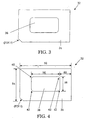
- Figure 3 illustrates a bottom view of the heat sink 32 illustrated in Figure 2.
- pedestal 36 is arranged in a center portion of the bottom edge 40 of body 34 of heat sink 32.
- the pedestal 36 of heat sink 32 is illustrated as being arranged in a center portion of the bottom edge 40 of body 34. Due to its size and shape, pedestal 36 extends below surface 40 into the space between surface 40 and warped surface 38 so that the size of gap 42 does not become larger than an acceptable gap limit value.
- the maximum value of the size of gap 42 may 0.13 mm (0.005 inches) or less or may be 7 mil or less, or may be 2 mil or less.
- a length 52 of the body 34 of the heat sink 32 is approximately in a range of 8.1 cm to 8.14 cm (3.195 inches to 3.205 inches), or approximately 8.13 cm (3.2 inches) (or approximately 3.2 inches maximum), or approximately 6.76 cm (2.66 inches) or approximately 7.62 cm (3 inches) (or approximately 3 inches maximum), and a width 54 of the body 34 of heat sink 32 is approximately in a range of 6.35 cm to 7.62 cm (2.5 inches to 3.0 inches), or approximately 6.25 cm (2.46 inches), or approximately 7.62 cm (3 inches) (or approximately a maximum of 3 inches), a length 56 of the pedestal 36 is approximately 5.33 cm (2.1 inches) (or approximately 2.1 inches maximum) and a width 58 of pedestal 36 is approximately 3.3 cm (1.3 inches) (or approximately 1.3 inches maximum), a distance 60 between an edge of body 34 and an edge of pedestal 36 is approximately 6.9 mm (0.27 inches), and a flatness (not illustrated) of pedestal 36 is approximately 0.025 mm per linear 2.54 cm
- a radius of the Comers 62 of pedestal 36 is approximately 7.62 mm (0.3 inches).
- An approximate depth of the pedestal 36 in an embodiment of the present invention is approximately 30 thousandths 0.76 mm (or 0.03 inches).
- An approximate value of the surface area of the bottom of pedestal 36 is approximately 17.1 cm 2 (2.65 square inches) or approximately 17.8 cm 2 (2.73 square inches), or approximately 6.9 cm 2 (2.7 square inches), or approximately in a range of 16.8 cm 2 to 18.1 cm 2 (2.6 square inches to 2.8 square inches).
- Pedestal 36 is approximately positioned in a center of bottom edge 40 of body 34. Additionally, in an alternative embodiment of the present invention the bottom of pedestal 36 is not approximately flat but is curved or otherwise shaped in a manner to advantageously follow the warped top surface 38 of electrical component 30 to further reduce the gap between the electrical component and the pedestal of the heat sink.
- pedestal 36 can be advantageously modified based on different particular electrical components 30 from which heat is being dissipated.
- the pedestal 36 is arranged in a center portion of the bottom surface 40 of the body 34 of the heat sink 32.
- the pedestal 36 can be formed of a plurality of legs (for example, two legs or four legs) extending from the bottom surface 40 of body 34 in a manner such that the gap between the pedestal legs and the warped top surface of the electrical component is minimized.
- the pedestal 36 is formed in any shape, size or position relative to the body of the heat sink such that a gap between the heat sink and the electrical component occurring due to warping or other deformation of the surface of the electrical component can be minimized.
- the bottom of the pedestal may be curved to ensure greater contact between the bottom edge of the pedestal and the warped surface of the electrical component.
- a fan or a plurality of fans may be provided on top of heat sink 32 to further enable heat dissipation.
- the electrical component has been described herein as being a Pentium® Pro processor or any other processor, it is noted that the heat sink according to embodiments of the present invention may be used to dissipate heat from any electrical component or any other device from which it is desired to dissipate heat.
Landscapes
- Cooling Or The Like Of Electrical Apparatus (AREA)
- Cooling Or The Like Of Semiconductors Or Solid State Devices (AREA)
Claims (10)
- Kühlkörper (32), der folgendes umfasst:einen Körper (34) mit einer unteren Oberfläche (40) mit einer Länge und einer Breite; undeinen Sockel (36) an der unteren Oberfläche (40) des Körpers (34), wobei der Sockel (36) eine Länge aufweist und eine Breite, die kleiner ist als die Länge und die Breite der unteren Oberfläche (38) des Körpers (34) und mit einem kleineren Oberflächenbereich als eine obere Oberfläche (38) eines zu kühlenden elektrischen Bauteils (30), wobei der Sockel (36) zwischen der unteren Oberfläche (40) des Körpers und einer konkaven, schalenartigen, gekrümmten oberen Oberfläche (38) des elektrischen Bauteils (30) angeordnet werden kann, um einen dazwischen ausgebildeten Zwischenraum (42) zu verringern.
- Kühlkörper (32) nach Anspruch 1, wobei dieser ferner eine Mehrzahl von Finnen (38) umfasst.
- Kühlkörper (32) nach Anspruch 1 oder 2, wobei es sich bei dem elektrischen Bauteil (30) um einen Prozessor handelt.
- Kühlkörper (32) nach einem der vorstehenden Ansprüche, wobei die Länge des Sockels (36) ungefähr im Bereich von 70% bis 90% der Länge der unteren Oberfläche (40) des Körpers (34) liegt.
- Kühlkörper (32) nach Anspruch 1, wobei die Länge des Sockels (38) ungefähr 80% der Länge der unteren Oberfläche (40) des Körpers (34) entspricht.
- Kühlkörper (32) nach Anspruch 5, wobei die Länge der unteren Oberfläche (40) des Körpers (34) im Bereich von ungefähr 6,35 cm bis 8,9 cm (2,5 Zoll bis 3,5 Zoll) liegt, und wobei die Länge des Sockels (36) im Bereich von ungefähr 5,1 cm bis 6,35 cm (2,0 Zoll bis 2,5 Zoll) liegt.
- Kühlkörper (32) nach Anspruch 6, wobei die Länge der unteren Oberfläche (40) des Körpers (34) ungefähr 6,76 cm (2,66 Zoll) entspricht, und wobei die Länge des Sockels (36) ungefähr 5,33 cm (2,1 Zoll) entspricht.
- Kühlkörper (32) nach einem der vorstehenden Ansprüche, wobei die Oberfläche des Sockels (36) ungefähr 17,1 cm2 (2,65 Quadratzoll) entspricht.
- Kühlkörper (32) nach einem der vorstehenden Ansprüche, wobei die untere Oberfläche (40) des Körpers (34) eine Oberfläche aufweist, die ungefähr im Bereich von 15,24 cm2 bis 16,51 cm2 (6,0 Quadratzoll bis 6,5 Quadratzoll) liegt.
- Kühlkörper (32) nach einem der vorstehenden Ansprüche, wobei der Körper (34) und der Sockel (36) des Kühlkörpers (32) aus Aluminium bestehen.
Applications Claiming Priority (3)
| Application Number | Priority Date | Filing Date | Title |
|---|---|---|---|
| US08/912,249 US6257327B1 (en) | 1997-08-15 | 1997-08-15 | Heat sink including pedestal |
| US912249 | 1997-08-15 | ||
| PCT/US1998/015208 WO1999009366A1 (en) | 1997-08-15 | 1998-07-22 | Heat sink including pedestal |
Publications (3)
| Publication Number | Publication Date |
|---|---|
| EP1015836A1 EP1015836A1 (de) | 2000-07-05 |
| EP1015836A4 EP1015836A4 (de) | 2002-03-06 |
| EP1015836B1 true EP1015836B1 (de) | 2004-06-09 |
Family
ID=25431586
Family Applications (1)
| Application Number | Title | Priority Date | Filing Date |
|---|---|---|---|
| EP98937980A Expired - Lifetime EP1015836B1 (de) | 1997-08-15 | 1998-07-22 | Wärmesenke mit sockel |
Country Status (6)
| Country | Link |
|---|---|
| US (1) | US6257327B1 (de) |
| EP (1) | EP1015836B1 (de) |
| AU (1) | AU8660298A (de) |
| DE (1) | DE69824427T2 (de) |
| TW (1) | TW572247U (de) |
| WO (1) | WO1999009366A1 (de) |
Families Citing this family (6)
| Publication number | Priority date | Publication date | Assignee | Title |
|---|---|---|---|---|
| US6691769B2 (en) * | 2001-08-07 | 2004-02-17 | International Business Machines Corporation | Heat sink for convection cooling in horizontal applications |
| US7100281B2 (en) * | 2004-03-15 | 2006-09-05 | International Business Machines Corporation | Heat sink and method of making the same |
| JP6352175B2 (ja) | 2011-07-08 | 2018-07-04 | コベストロ、ドイチュラント、アクチエンゲゼルシャフトCovestro Deutschland Ag | ジアリールカーボネートの製造方法 |
| KR101980394B1 (ko) | 2011-07-08 | 2019-05-20 | 코베스트로 도이칠란드 아게 | 디아릴 카르보네이트의 제조 방법 |
| US10914539B2 (en) | 2013-05-15 | 2021-02-09 | Osram Sylvania Inc. | Two piece aluminum heat sink |
| US20250285935A1 (en) * | 2024-03-07 | 2025-09-11 | Nxp B.V. | Electronic device with warpage mitigation and method therefor |
Family Cites Families (20)
| Publication number | Priority date | Publication date | Assignee | Title |
|---|---|---|---|---|
| US4535385A (en) * | 1983-04-22 | 1985-08-13 | Cray Research, Inc. | Circuit module with enhanced heat transfer and distribution |
| DE3335377A1 (de) * | 1983-09-29 | 1985-04-11 | Siemens AG, 1000 Berlin und 8000 München | Einrichtung zum festhalten eines kuehlkoerpers auf einem integrierten baustein |
| GB8601746D0 (en) * | 1986-01-24 | 1986-02-26 | British Telecomm | Heat sink |
| US5132780A (en) * | 1988-01-07 | 1992-07-21 | Prime Computer, Inc. | Heat sink apparatus with an air deflection member |
| FR2679729B1 (fr) * | 1991-07-23 | 1994-04-29 | Alcatel Telspace | Dissipateur thermique. |
| US5168926A (en) * | 1991-09-25 | 1992-12-08 | Intel Corporation | Heat sink design integrating interface material |
| US5172755A (en) * | 1992-04-01 | 1992-12-22 | Digital Equipment Corporation | Arcuate profiled heatsink apparatus and method |
| US5270902A (en) * | 1992-12-16 | 1993-12-14 | International Business Machines Corporation | Heat transfer device for use with a heat sink in removing thermal energy from an integrated circuit chip |
| US5367193A (en) * | 1993-06-17 | 1994-11-22 | Sun Microsystems, Inc. | Low cost, thermally efficient, and surface mountable semiconductor package for a high applied power VLSI die |
| US5654587A (en) * | 1993-07-15 | 1997-08-05 | Lsi Logic Corporation | Stackable heatsink structure for semiconductor devices |
| US5424580A (en) * | 1993-11-01 | 1995-06-13 | Unisys Corporation | Electro-mechanical assembly of high power and low power IC packages with a shared heat sink |
| JP2646994B2 (ja) * | 1993-12-29 | 1997-08-27 | 日本電気株式会社 | ヒートシンク付ピングリッドアレイ |
| US5574626A (en) * | 1995-07-12 | 1996-11-12 | Unisys Corporation | Add-on heat sink |
| JP3540471B2 (ja) * | 1995-11-30 | 2004-07-07 | 三菱電機株式会社 | 半導体モジュール |
| US5638895A (en) * | 1996-03-25 | 1997-06-17 | Dodson; Douglas A. | Twin fan cooling device |
| US5740014A (en) * | 1996-12-11 | 1998-04-14 | Lin; Chun Sheng | CPU heat sink |
| US5875096A (en) * | 1997-01-02 | 1999-02-23 | At&T Corp. | Apparatus for heating and cooling an electronic device |
| US5784254A (en) * | 1997-01-13 | 1998-07-21 | Delco Electronics Corporation | Slide mount spring clamp arrangement for attaching an electrical component to a convector |
| US5808236A (en) * | 1997-04-10 | 1998-09-15 | International Business Machines Corporation | High density heatsink attachment |
| US5847452A (en) * | 1997-06-30 | 1998-12-08 | Sun Microsystems, Inc. | Post mounted heat sink method and apparatus |
-
1997
- 1997-08-15 US US08/912,249 patent/US6257327B1/en not_active Expired - Lifetime
-
1998
- 1998-07-22 AU AU86602/98A patent/AU8660298A/en not_active Abandoned
- 1998-07-22 WO PCT/US1998/015208 patent/WO1999009366A1/en not_active Ceased
- 1998-07-22 EP EP98937980A patent/EP1015836B1/de not_active Expired - Lifetime
- 1998-07-22 DE DE69824427T patent/DE69824427T2/de not_active Expired - Fee Related
- 1998-07-29 TW TW090215713U patent/TW572247U/zh not_active IP Right Cessation
Also Published As
| Publication number | Publication date |
|---|---|
| WO1999009366A1 (en) | 1999-02-25 |
| DE69824427T2 (de) | 2005-06-16 |
| US6257327B1 (en) | 2001-07-10 |
| WO1999009366A9 (en) | 1999-05-06 |
| TW572247U (en) | 2004-01-11 |
| EP1015836A4 (de) | 2002-03-06 |
| DE69824427D1 (de) | 2004-07-15 |
| AU8660298A (en) | 1999-03-08 |
| EP1015836A1 (de) | 2000-07-05 |
Similar Documents
| Publication | Publication Date | Title |
|---|---|---|
| US6515862B1 (en) | Heat sink assembly for an integrated circuit | |
| US6691768B2 (en) | Heatsink design for uniform heat dissipation | |
| US6554060B2 (en) | Heat sink with fins | |
| US6883593B2 (en) | Heat sink for convection cooling in horizontal applications | |
| US6446708B1 (en) | Heat dissipating device | |
| EP1117130A2 (de) | Kühlkörperherstellung und Kühler damit | |
| US5903436A (en) | Emulative lid/heatspreader for processor die attached to an organic substrate | |
| US20090059524A1 (en) | Heat dissipation device | |
| US7131487B2 (en) | Use of adjusted evaporator section area of heat pipe that is sized to match the surface area of an integrated heat spreader used in CPU packages in mobile computers | |
| US6862183B2 (en) | Composite fins for heat sinks | |
| JP2004047998A (ja) | 複数のフィンタイプを備えた放熱器 | |
| US6657865B1 (en) | Heat dissipating structure | |
| US6977814B2 (en) | Dual material heat sink core assembly | |
| WO2001020675A1 (en) | Heat sink including heat receiving surface with protruding portion | |
| EP1015836B1 (de) | Wärmesenke mit sockel | |
| US20070044942A1 (en) | Bottom plate of a radiator for a CPU | |
| JP2845833B2 (ja) | ヒートシンク | |
| JP2000353889A (ja) | 冷却装置 | |
| JP3840970B2 (ja) | ヒートシンク | |
| US6636423B2 (en) | Composite fins for heat sinks | |
| US20050237718A1 (en) | Fan-shaped heat-dissipating device | |
| US7363964B2 (en) | Heat sink | |
| US6501655B1 (en) | High performance fin configuration for air cooled heat sinks | |
| JPH08153835A (ja) | 冷却構造 | |
| KR200248523Y1 (ko) | 집적 회로용 냉각 장치 어셈블리 |
Legal Events
| Date | Code | Title | Description |
|---|---|---|---|
| PUAI | Public reference made under article 153(3) epc to a published international application that has entered the european phase |
Free format text: ORIGINAL CODE: 0009012 |
|
| 17P | Request for examination filed |
Effective date: 20000313 |
|
| AK | Designated contracting states |
Kind code of ref document: A1 Designated state(s): DE FR GB |
|
| A4 | Supplementary search report drawn up and despatched |
Effective date: 20020118 |
|
| AK | Designated contracting states |
Kind code of ref document: A4 Designated state(s): DE FR GB |
|
| RIC1 | Information provided on ipc code assigned before grant |
Free format text: 7F 28F 7/00 A, 7H 01L 23/26 B, 7H 01L 23/34 B, 7H 05K 7/20 B, 7H 01L 23/367 B |
|
| 17Q | First examination report despatched |
Effective date: 20030424 |
|
| GRAP | Despatch of communication of intention to grant a patent |
Free format text: ORIGINAL CODE: EPIDOSNIGR1 |
|
| GRAS | Grant fee paid |
Free format text: ORIGINAL CODE: EPIDOSNIGR3 |
|
| GRAA | (expected) grant |
Free format text: ORIGINAL CODE: 0009210 |
|
| AK | Designated contracting states |
Kind code of ref document: B1 Designated state(s): DE FR GB |
|
| PG25 | Lapsed in a contracting state [announced via postgrant information from national office to epo] |
Ref country code: FR Free format text: LAPSE BECAUSE OF FAILURE TO SUBMIT A TRANSLATION OF THE DESCRIPTION OR TO PAY THE FEE WITHIN THE PRESCRIBED TIME-LIMIT Effective date: 20040609 |
|
| REG | Reference to a national code |
Ref country code: GB Ref legal event code: FG4D |
|
| REF | Corresponds to: |
Ref document number: 69824427 Country of ref document: DE Date of ref document: 20040715 Kind code of ref document: P |
|
| PLBE | No opposition filed within time limit |
Free format text: ORIGINAL CODE: 0009261 |
|
| STAA | Information on the status of an ep patent application or granted ep patent |
Free format text: STATUS: NO OPPOSITION FILED WITHIN TIME LIMIT |
|
| 26N | No opposition filed |
Effective date: 20050310 |
|
| EN | Fr: translation not filed | ||
| PGFP | Annual fee paid to national office [announced via postgrant information from national office to epo] |
Ref country code: GB Payment date: 20090727 Year of fee payment: 12 Ref country code: DE Payment date: 20090729 Year of fee payment: 12 |
|
| GBPC | Gb: european patent ceased through non-payment of renewal fee |
Effective date: 20100722 |
|
| PG25 | Lapsed in a contracting state [announced via postgrant information from national office to epo] |
Ref country code: DE Free format text: LAPSE BECAUSE OF NON-PAYMENT OF DUE FEES Effective date: 20110201 |
|
| REG | Reference to a national code |
Ref country code: DE Ref legal event code: R119 Ref document number: 69824427 Country of ref document: DE Effective date: 20110201 |
|
| PG25 | Lapsed in a contracting state [announced via postgrant information from national office to epo] |
Ref country code: GB Free format text: LAPSE BECAUSE OF NON-PAYMENT OF DUE FEES Effective date: 20100722 |