EP1117130A2 - Kühlkörperherstellung und Kühler damit - Google Patents
Kühlkörperherstellung und Kühler damit Download PDFInfo
- Publication number
- EP1117130A2 EP1117130A2 EP01100757A EP01100757A EP1117130A2 EP 1117130 A2 EP1117130 A2 EP 1117130A2 EP 01100757 A EP01100757 A EP 01100757A EP 01100757 A EP01100757 A EP 01100757A EP 1117130 A2 EP1117130 A2 EP 1117130A2
- Authority
- EP
- European Patent Office
- Prior art keywords
- heatsink
- column
- heat receiving
- receiving face
- heat
- Prior art date
- Legal status (The legal status is an assumption and is not a legal conclusion. Google has not performed a legal analysis and makes no representation as to the accuracy of the status listed.)
- Withdrawn
Links
Images






Classifications
-
- F—MECHANICAL ENGINEERING; LIGHTING; HEATING; WEAPONS; BLASTING
- F28—HEAT EXCHANGE IN GENERAL
- F28F—DETAILS OF HEAT-EXCHANGE AND HEAT-TRANSFER APPARATUS, OF GENERAL APPLICATION
- F28F3/00—Plate-like or laminated elements; Assemblies of plate-like or laminated elements
- F28F3/02—Elements or assemblies thereof with means for increasing heat-transfer area, e.g. with fins, with recesses, with corrugations
- F28F3/04—Elements or assemblies thereof with means for increasing heat-transfer area, e.g. with fins, with recesses, with corrugations the means being integral with the element
-
- H—ELECTRICITY
- H10—SEMICONDUCTOR DEVICES; ELECTRIC SOLID-STATE DEVICES NOT OTHERWISE PROVIDED FOR
- H10W—GENERIC PACKAGES, INTERCONNECTIONS, CONNECTORS OR OTHER CONSTRUCTIONAL DETAILS OF DEVICES COVERED BY CLASS H10
- H10W40/00—Arrangements for thermal protection or thermal control
- H10W40/20—Arrangements for cooling
- H10W40/22—Arrangements for cooling characterised by their shape, e.g. having conical or cylindrical projections
- H10W40/226—Arrangements for cooling characterised by their shape, e.g. having conical or cylindrical projections characterised by projecting parts, e.g. fins to increase surface area
- H10W40/228—Arrangements for cooling characterised by their shape, e.g. having conical or cylindrical projections characterised by projecting parts, e.g. fins to increase surface area the projecting parts being wire-shaped or pin-shaped
-
- H—ELECTRICITY
- H10—SEMICONDUCTOR DEVICES; ELECTRIC SOLID-STATE DEVICES NOT OTHERWISE PROVIDED FOR
- H10W—GENERIC PACKAGES, INTERCONNECTIONS, CONNECTORS OR OTHER CONSTRUCTIONAL DETAILS OF DEVICES COVERED BY CLASS H10
- H10W70/00—Package substrates; Interposers; Redistribution layers [RDL]
- H10W70/01—Manufacture or treatment
- H10W70/02—Manufacture or treatment of conductive package substrates serving as an interconnection, e.g. of metal plates
- H10W70/027—Mechanical treatments, e.g. deforming, punching or cutting
-
- Y—GENERAL TAGGING OF NEW TECHNOLOGICAL DEVELOPMENTS; GENERAL TAGGING OF CROSS-SECTIONAL TECHNOLOGIES SPANNING OVER SEVERAL SECTIONS OF THE IPC; TECHNICAL SUBJECTS COVERED BY FORMER USPC CROSS-REFERENCE ART COLLECTIONS [XRACs] AND DIGESTS
- Y10—TECHNICAL SUBJECTS COVERED BY FORMER USPC
- Y10T—TECHNICAL SUBJECTS COVERED BY FORMER US CLASSIFICATION
- Y10T29/00—Metal working
- Y10T29/49—Method of mechanical manufacture
- Y10T29/4935—Heat exchanger or boiler making
- Y10T29/49359—Cooling apparatus making, e.g., air conditioner, refrigerator
Definitions
- the present invention relates to a heatsink which is used to cool heat producing semiconductor elements abbreviated such as IC, CPU, MPU or the like and electronic components including heating sections.
- the present invention also relates to methods of manufacturing a heatsink, and to a cooling apparatus using the heatsink.
- the cooling apparatus uses the heatsink combined with cooling means such as a fan for cooling the heat producing elements.
- Heat emitted from the electronic components is, in general, dissipated by a cooling apparatus comprising a heatsink and a fan.
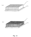
- Fig. 12 shows a perspective view of a conventional heatsink.
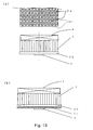
- Fig. 13 shows a top view and sectional views of a conventional cooling apparatus.
- Fig. 14 shows a perspective view and a side view of another conventional heatsink.
- These heatsinks can be categorized into a plate-type heatsink where a plurality of plate fins 1c made of thin plates are disposed on a base plate 2b or a heat conduction section as shown in Fig. 12 (a) , a pin-type heatsink where a plurality of fins 1 are disposed on the plate 2b as shown in Fig.
- heatsinks are generally constructed of materials with high heat conductivity such as aluminum and copper, and produced by the extrusion molding (otherwise called pultrusion molding) method, the cold forging method, the die casting method, or the thin plates accumulating method.
- the heatsinks are mounted either directly onto a heat producing element 3 as illustrated in Fig. 13 (a), or indirectly by inserting a heat diffusion plate 2c between the heat producing element 3 and the heatsink as illustrated in Fig. 13 (b) in the case of the pin-type heatsink.
- the heat diffusion plate conducts heat emitted from the heat producing element 3 to the heatsink, and helps to diffuse the heat and protect the heat producing element.
- the cooling mechanism of the cooling apparatus in use is described as follows: heat produced by the heat producing element 3 is conducted to the pin-shaped fins 1 via the heat-conductive base plate 2b made of a highly heat conductive material such as aluminum, and, over the surface of the fins 1, convectively conducted to the air blown by a cooling fan 4 thus dissipated into the air and cooled.
- heat is most desirably diffused throughout the heat conductive section evenly, and dissipated from all of the dissipation fins.
- heat emitted from the heat producing element 3 tends to be conducted intensively to the dissipation fins disposed right above the heat producing element 3. It is relatively hard for the heat to be conducted to the peripheral dissipation fins. The reason for this is that the heat producing element is much smaller than the heat conducting section, thus contact area between them is very limited. Consequently, with the plate-type and the pin-type heatsinks, the heat dissipation fins as a whole often fail to function effectively.
- the heat dissipating capability can be increased by expanding the surface area by increasing the number of fins.
- the area where air can flow into such as an air flow area 7e (marked with diagonal lines in Fig. 13 (a)) decreases, as does the total volume of air flow. Therefore, in some cases, the heat dissipation capability lowers as a result. In other words, a mere increase in the number of dissipation fins does not bring about an improvement.
- the most important aspect for the dissipation of heat is to effectively conduct heat produced by the heat producing element 3 to the dissipation fins to the largest possible area.
- the tower-type heatsink shown in Fig. 14 has been introduced.
- heat produced in the heat producing element is conducted directly to the upper part of the heatsink by a central column, and spread flatly by the plate fins 1c formed at a right angle to the axis of the column.
- the heat which has been spread flatly on the both faces of the thin plates is generally dissipated into the air by natural air cooling.
- improvements have been proposed to increase the dissipation capability. For example, Japanese Patent Laid Open Publication No.
- S62-182600 discloses a heatsink where through-hole vents are formed on the surface of the thin plates by cutting and standing the cut edges of the thin plates in the process of producing the plate fins. Through these vents, air is permitted to convect more easily in the direction parallel to the axis of the column.
- the construction of the tower-type heatsink realizes a better heat conductivity, however, it also tends to trap air. Furthermore, it is difficult to dispose a cooling fan on the top of the tower-type heatsink, therefore, the cooling fan must be disposed on a side face of the heatsink. However, if the cooling fan is disposed in such a manner, the heatsink is required to be as high as the cooling fan. Thus, the cooling apparatus as a whole becomes remarkably large. Despite its size, however, the dissipation efficiency can not be improved satisfactorily.
- the present invention aims to address the foregoing problems, and to provide a compact and highly efficient heatsink and a small cooling apparatus with high cooling ability using the heatsink.
- the present invention further aims at providing a manufacturing method of the heatsink which achieves the production of a highly effective heatsink in a productive and inexpensive manner.
- a heatsink of the present invention has a column having a heat conducting plate with a heat receiving face in contact with a heat producing element. On the side faces of the column are a plurality of first slits disposed parallel to the heat receiving face and a plurality of second slits disposed transversely to the heat receiving face. These slits form a plurality of pillar-type protrusions functioning as cooling fins.
- the pillar-type protrusions are called fins.
- Another heatsink of the present invention includes a heat conducting plate section having a heat receiving face and a column which acts as a heat conducting section by protruding opposite the heat receiving face of the heat conducting plate section.
- At least one cross section of the column has a shape of a rectangle, a trapezoid, a triangle or some shape which tapers off as it goes away at right angle from the heat receiving face.
- On the side faces of the column are a plurality of fins formed along the heat receiving face.
- the heatsink of the present invention is compact, it can effectively lead the heat produced by the heat producing element throughout the heatsink, thus realizing high heat dissipating properties.
- the heatsinks which have especially superior heat dissipating properties include the following types:
- the dissipation effect of heat into air is especially enhanced.
- the method of manufacturing the heatsink of the present invention includes first and second processes.
- the first slits are formed by providing a plurality of metallic plate fins in the column and its length directions by the methods including extrusion molding using a metallic mold.
- the second slits are formed in a direction approximately transverse to the length direction of the plate fins.
- This manufacturing method achieves productive and inexpensive production of high-performance heatsinks.
- a cooling apparatus of the present invention includes a cooling means mounted on the heatsink of the present invention. Mounting a wind blowing means such as a fan opposite the heat receiving face allows the cooling apparatus of the present invention to enjoy a high cooling capability and to be reduced in size.
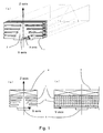
- Fig. 1 shows a perspective view and side views of the main part of a heatsink in accordance with a first preferred embodiment of the present invention.
- Fig. 2 shows a perspective view illustrating the external shape of a heatsink and sectional views of columns of the heat sinks in accordance with the first preferred embodiment of the present invention.
- Fig. 3 shows plan views and side views of a heatsink in accordance with a second preferred embodiment of the present invention.
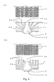
- Fig. 4 shows plan views and side views of a heatsink in accordance with the second preferred embodiment of the present invention.
- Fig. 5 shows a perspective view of fins of the heatsink in accordance with the first and second preferred embodiments of the present invention.
- Fig. 6 shows front views and side views of the heatsink and the cooling apparatus in accordance with the first and second preferred embodiments of the present invention.
- Fig. 7 shows side views which illustrate air flow of the heatsink and the cooling apparatus in accordance with the first and second preferred embodiments of the present invention.
- Fig. 8 shows a perspective view illustrating a manufacturing method of the heatsink in accordance with the first and second preferred embodiments of the present invention.
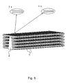
- Fig. 9 shows perspective views illustrating an extrusion process of the heatsink in accordance with the first and second preferred embodiments of the present invention.
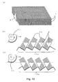
- Fig. 10 shows a perspective view of the heatsink and side views of the heatsink placed on a jig during a cutting process of the heatsink in accordance with the first and second preferred embodiments of the present invention.
- Fig. 11 shows perspective views of the cooling apparatus having cooling fans mounted on the top of the heatsink in accordance with the first and second preferred embodiments of the present invention.
- Fig. 12 shows perspective views illustrating construction of a conventional heatsink.
- Fig. 13 shows a plan view and sectional views of a conventional cooling apparatus.
- Fig. 14 shows a perspective view and a side view illustrating construction of a conventional heatsink.
- Fig. 1 shows a perspective view and side views of the main part of a heatsink in accordance with a first preferred embodiment of the present invention.
- Fig. 1 (a) is a perspective view of the heatsink according to the first preferred embodiment of the present invention.
- Fig. 1 (b) is a sectional view of a cooling apparatus of the present invention disposed right on the top of a heat producing element 3 viewed from the perspective of the length direction of a column 2 (hereinafter, Y axis direction) when a cooling fan 4 is mounted.
- Fig. 1 (c) is a side view of a cooling apparatus of the present invention viewed from the perspective of the width direction of the column 2 (hereinafter, X axis direction) when the cooling fan 4 is mounted.
- Fig. 2 shows a perspective view illustrating the external shape of a heatsink and sectional views of columns of the heatsink in accordance with the first embodiment of the present invention.
- Fig. 2 (a) is a perspective view of the external shape (drawn by broken line) of the heatsink of the first embodiment of the present invention.
- Figs. 2 (b)-(e) show plan views and side views of the heatsink of the first embodiment of the present invention with different sectional shapes.
- a plurality of fins 1 are disposed on the column 2 (or heat conducting section).
- the heat producing element 3 is disposed under the column 2 (hereinafter, negative Z axis direction).
- the cooling fan 4 On the top of the heatsink is the cooling fan 4.
- the heatsink comprises the fins 1 and the column 2.
- the heat producing element 3 here is an electronic component which produces heat including transistors and semiconductors such as IC, LSI, MPU or the like.
- width, length and height directions of the column are, in some cases, expressed as X axis, Y axis and Z axis directions as mentioned previously.
- the column 2 is a prism of which a cross section through Y axis direction is a triangle. Creating the shape of the column 2 in this manner improves contact between the column 2 and the heat producing element 3 and reduces waste of the materials. It especially contributes to providing a heatsink with superior mountability and heat conductivity.
- the column 2 has fins 1 disposed thereon. The fins 1 in Fig. 1 are disposed on both faces of the column.
- the construction of the heatsink of the present invention can realize a compact cooling apparatus having superior heat conductivity and heat dissipation properties.
- heat produced by the heat producing element 3 is received on the bottom surface of the prism column 2 (or heat receiving face) which contacts with the heating surface of the heat producing element 3.
- the heat is then diffused three-dimensionally to in the directions of the X, Y and Z axes from the bottom surface of the column 2.
- the column 2 is a prism, a stable hemispherical temperature distribution can be achieved over a much larger area inside the column compared with the plate heat conducting section of the conventional plate-type and pin-type heatsinks.
- the heat emitted from the heat producing element 3 is conducted over the hemispherical temperature distribution range and to the fins 1 which function as heat dissipating fins.
- the heatsink of this embodiment achieves significantly higher heat dissipation properties than the conventional heatsinks of the same size. Furthermore, even in the vicinity of both ends of the heatsink where such hemispherical temperature distribution is hard to obtain, fins 1 can sufficiently function as heat dissipation fins since the sectional area of the column 2 is large enough to maintain a low heat resistance associated with the transfer of heat.
- Figs. 2 (b) and (c) shows constructions of a plurality of other embodiments where the sectional shapes of column 2 of the heatsink illustrated in Fig. 1 are changed.
- differences in sectional shapes of the column 2 produces difference in the sectional area of the column 2 and the sectional area of an air flow section of which opening is placed on the cooling fan side at the top.
- Fig. 2(a) shows the condition of the column 2 when the cross section of the column shown in Fig. 1 is triangular.
- the sectional area of the column 2 which directly affects the diffusion of the heat becomes progressively smaller according to its shape in the following order; square shown in Fig. 2 (e) , trapezoid, in Fig.
- the sectional area of the air flow section which is concerned with the volume of air which dissipates heat outside, becomes larger as the length of a side A and a side B having an opening on the top of the heatsink becomes longer.
- the sectional area of the air flow section expands according to the shape of the column in the following order; square, shown in Fig. 2 (e), trapezoid, in Fig. 2 (c), triangle, in Fig. 2 (d), and bell-shape, in Fig. 2 (e). It is desirable to provide the air flow section with the largest possible sectional area so as to obtain sufficient volume of air flow.
- the sectional area of the column 2 which conducts heat produced by the heat producing element 3 as well as the area of the air flow section are the largest possible so as to obtain the maximum air flow necessary for dissipating heat.
- the two have in some ways a conflicting relationship.
- what is needed is to select the shape of the column 2 with the largest possible sectional area while maintaining the maximum air flow area to ensure sufficient volume of air to dissipate heat.
- ones in Figs. 2 (d) and (e) are desirable since the air flow sections have sufficient width (the total length of the sides A and B) and the sectional area of the column 2 is large.
- end faces of the fins 1 and the bottom corners of the column 2 are desirably chamfered.
- the chamfering prevents chipping and generation of undesirable material. If a corner is sharp, the heatsink may contact with other components when it is being mounted onto an electronic component and break the component. When material is generated from a chipped corner and falls on wiring, it might trigger a short circuit and cause the electronic apparatus to malfunction.
- the column 2 and the fins 1 can be integrally formed, or the fins can be adhered to the column 2 as separate parts with adhesives. As another method, the fins 1 can be press fitted into holes provided on the column 2.
- a square pole as shown in Fig. 1 a cylinder, a polygonal pole, a elliptic cylinder and the like can be used.
- the fins 1 By forming the fins 1 to have a shape of square pole, the mounting density of the fins 1 can be enhanced, thereby improving the heat dissipation.
- thickness of the fins 1 was set approximately the same.
- the fins 1 can be designed such that they have a taper of which either the thickest or thinnest part is fixed to the column 2.
- the fins 1 can also be designed so that the center of it is thinner or thicker than the other parts.
- the fins 1 are disposed at regular intervals, heat dissipation and productivity are desirably improved.
- the convection of air improves, and the manufacturing of the heatsink is faciliated.
- Desirable materials for the heatsinks are ones which have a heat conductivity at 100oC of 100k/W ⁇ m -1 ⁇ K -1 or more.
- Such materials can be selected from zinc, aluminum, brass, gold, silver, tungsten, copper, beryllium, magnesium, and molybdenum (hereinafter, material group), and used in their pure form. These materials can also be used in an alloy form. In the latter case it is possible to either select a plurality of alloys from the above-mentioned group or select at least one from the material group and alloying it with materials not included in the above group. In this embodiment, aluminum and an aluminum alloy and at least one other material selected from the material group were used because of its ease of processing and low cost.
- Figs. 3 and 4 show plan views and side views of the second embodiment of the present invention in which the construction of the column and fins of the heatsink is changed.
- the axis of the fins 1 are set at right angle against a base line 9a which is vertical to the heating face of the column 2.
- the cooling fan is mounted on the top of the heatsink. Air blown by the cooling fan travels through an air flow section 7a (gap between fins) marked with diagonal lines and the heatsink from the top to the bottom similar to an air current 5a to radiate heat of the fins 1.
- the only possible disadvantageous point is that the air flow area per unit area is smaller than that of the conventional heatsink shown in Fig. 13 (a) when size of the top part of which is the same.
- the area is calculated by subtracting the total area of all of the fins 1 from the total area on the top surface of the heatsink.
- approximately 50% of the area on the top surface of the heatsink is covered with the side faces of the fins 1. Therefore, the air flow area is reduced by that amount.
- the axis of the fins 1 are set such that it has a predetermined angle ⁇ against the base line 9a.
- the air flow section 7b can be extended even wider than the conventional heatsink shown in Fig. 13 (a) while maintaining the surface area of the fins and height of the heatsink at the same level as the heatsink described in Fig. 3.
- the heatsink illustrated in Fig. 3 (b) has the air flow section twice as large as the air flow section 7a illustrated in Fig. 3 (a), thus realizing even higher heat dissipation properties. Furthermore, since the fins 1 are tilted by an angle ⁇ and positioned, air flow coming in from the top of the heatsink becomes an air flow 5b. The air flow 5b then is led along the top surface of the fins 1 to the surface of the column 2 in addition to the air flow 5a, thereby further improving the heat dissipation properties.
- Fig. 4 (a) shows a heatsink which has the fins 1 disposed radially with one point on the base line 9a as base point.
- the air flow area can be increased as in the case of Fig. 3 (b) compared with Fig. 3 (a), further enhancing the heat dissipation properties.
- Fig. 4 (b) shows the heatsink of Fig. 3 (a) in which the fins 1 are bent at right angles.
- Such heatsinks can also achieve the same performance properties as the heatsinks illustrated in Fig. 3 (b) and Fig. 4 (a).
- Fig. 5 shows a perspective view of the fins of the heatsink in accordance with the first and second preferred embodiments of the present invention.
- the external shape of the fins 1 in Fig. 5 illustrates, by forming protrusions and recesses on the surface of the fins 1 of the heatsink, the surface area increases enhancing the heat dissipating capability.
- the protrusions and recesses can be formed only on a part of the fins 1. Furthermore, even if they are formed on some of the fins, the same effect can be obtained.
- the surface of the fins 1 can be provided with dimples.
- the fins 1 can be formed such that the width near the bottom and the top end are the same as shown in Fig. 5 1a.
- the fins 1 can also be formed such that they have diminishing taper either from bottom to top or top to bottom as shown in Fig. 5 1b.
- Figs. 6 (a) and (b) show front views and side views of the heatsink and the cooling apparatus in accordance with the first and second preferred embodiments of the present invention.
- Figs. 7 (a), (b) and (c) show side views which illustrate air flow of the cooling apparatus.
- Figs. 6 (a) and (b) show, the whole face or part of the face where the heat producing element is mounted, has a protuberant heat conducting plate section 2a formed thereon.
- the plate section 2a some space can be provided in between the heat receiving face and the fins 1 disposed in the vicinity of the plate section 2a. Therefore, air flow created by the cooling fan 4 can be effectively led to the surface of the fins 1 near the heat receiving face.
- a heat receiving face is formed on the heat producing element mounting section of the plate section 2a.
- Figs. 7 (b) and (c) a comparison is made between the columns 2 with and without the plate section 2a on condition that the heat diffusion plate 2c and the heat producing element 3 are provided.
- the fins 1 near the heat receiving face contact directly with the heat diffusing plate 2c because of the absence of the plate section 2a. Therefore, air can not be sent to the fins 1 disposed on the lower part.
- the plate section 2a is provided on the column 2.
- Fig. 8 (a) shows the initial condition of a heat conductive material 6.
- Fig. 8 (b) shows a first process in which a plurality of plate fins 1c are formed along the length of the column 2 by a cutting, extrusion or pultrusion method.
- Fig. 8 (c) shows a second process in which a plurality of fins 1 are formed on both side faces of the column 2 by providing slits at right angle to the length of the plate fins 1c.
- the first process is conducted by a cutting, extrusion or pultrusion method.
- the example below refers to the extrusion method.
- a high-temperature heat conductive material is pressed into an extrusion die 10 in the direction marked by an arrow. Successively, the material 6 is pressed out and plastically deformed into the same shape as the mold cavity. At this point, the column 2 and the plate fins 1c are formed simultaneously as shown in Fig. 8 (b). The first process is completed by cutting at a predetermined length the material 6 which is pressed out from the mold cavity as shown in Fig. 9 (c).
- the shape of the heatsink having a plurality of fins shown in Fig. 10 (a) is formed by the machine cutting process.
- a cutting tool 11 is used to slit a plurality of heatsinks which are placed parallel to one another on a tilted jig 12a, so as to convert plate fins on one side to a plurality of fins 1.
- Fig. 10 (c) shows the plate fins 1c on the other side are machined to modify them to the fins 1.
- the second process can be processed by the laser cutting method.
- This embodiment achieves efficient and low cost manufacture of compact and high-performance heatsinks with a plurality of fins.
- the heatsinks produced by the manufacturing method of this embodiment have thoroughly one-piece construction, therefore they can achieve a remarkably superior heat dissipation capability.
- Fig. 11 shows perspective views of the cooling apparatus having cooling fans mounted on the top of the heatsink in accordance with the first and second preferred embodiments of the present invention.
- Figs. 11 (a) and (b) show the cooling apparatus where one cooling fan and two cooling fans are respectively disposed on the heatsink of the present invention.
- the cooling fan 4 can be mounted on top of the heatsink with screws, adhesives, clips, belt, or clip pins.
- the height of the heatsink of the present invention can be lowered while maintaining high cooling capability. Therefore, the overall height can be kept low even when the cooling fan 4 is mounted, thereby achieving a compact cooling apparatus.
- the cooling fan 4 was used in this embodiment, however, heat exchange elements such as Peltier elements can alternatively be used as a cooling means.
- a heat pipe can be used to transfer the heat of the heatsink to an other place to cool it down. It is also possible to immerse the heatsink into liquid to cool it down.
- the heatsink of the present invention which forms part of the cooling apparatus of this embodiment has fins on both side faces of the column 2 functioning as a heat conducting section.
- the cooling apparatus of this embodiment will allow superior cooling capability compared with a conventional cooling apparatus of the same volume. In other words, when the performance is set to be the same as that of the conventional cooling apparatus, the cooling apparatus of this embodiment can be the smaller and the lighter.
- the heatsinks of the present invention improve the diffusing effect of the heat produced by the heat producing element by introducing a heat conducting section of a pole-type column. Furthermore, sufficient heat dissipating area can be secured since the fins are provided on both faces of the column, thereby realizing high heat dissipation capability and a reduction in size.
- the manufacturing method of the heatsink of the present invention provides productive and low-cost manufacturing of high performance heatsinks.
Landscapes
- Engineering & Computer Science (AREA)
- Physics & Mathematics (AREA)
- Thermal Sciences (AREA)
- Mechanical Engineering (AREA)
- General Engineering & Computer Science (AREA)
- Cooling Or The Like Of Semiconductors Or Solid State Devices (AREA)
- Cooling Or The Like Of Electrical Apparatus (AREA)
Applications Claiming Priority (2)
| Application Number | Priority Date | Filing Date | Title |
|---|---|---|---|
| JP2000005533 | 2000-01-14 | ||
| JP2000005533A JP3431004B2 (ja) | 2000-01-14 | 2000-01-14 | ヒートシンクおよびそれを用いた冷却装置 |
Publications (2)
| Publication Number | Publication Date |
|---|---|
| EP1117130A2 true EP1117130A2 (de) | 2001-07-18 |
| EP1117130A3 EP1117130A3 (de) | 2003-11-19 |
Family
ID=18534190
Family Applications (1)
| Application Number | Title | Priority Date | Filing Date |
|---|---|---|---|
| EP01100757A Withdrawn EP1117130A3 (de) | 2000-01-14 | 2001-01-12 | Kühlkörperherstellung und Kühler damit |
Country Status (5)
| Country | Link |
|---|---|
| US (2) | US7040388B1 (de) |
| EP (1) | EP1117130A3 (de) |
| JP (1) | JP3431004B2 (de) |
| DE (1) | DE1117130T1 (de) |
| TW (1) | TW444369B (de) |
Cited By (4)
| Publication number | Priority date | Publication date | Assignee | Title |
|---|---|---|---|---|
| WO2004084301A1 (en) * | 2003-03-13 | 2004-09-30 | Intel Corporation | Split fin heat sink |
| GB2412499A (en) * | 2004-03-26 | 2005-09-28 | Yung-Pin Kuo | Heat sink |
| US20130118713A1 (en) * | 2011-09-21 | 2013-05-16 | Enermax Technology Corporation | Liquid cooling heat exchanger module |
| WO2022101552A1 (en) * | 2020-11-13 | 2022-05-19 | Teknologian Tutkimuskeskus Vtt Oy | Heat sink as well as apparatus and method of producing the same |
Families Citing this family (31)
| Publication number | Priority date | Publication date | Assignee | Title |
|---|---|---|---|---|
| CN2672865Y (zh) * | 2003-11-14 | 2005-01-19 | 鸿富锦精密工业(深圳)有限公司 | 散热器 |
| WO2006017301A2 (en) * | 2004-07-13 | 2006-02-16 | Thorrn Micro Technologies, Inc. | Micro-channel heat sink |
| JP2006319142A (ja) * | 2005-05-12 | 2006-11-24 | Sanyo Denki Co Ltd | 発熱体冷却装置及びヒートシンク |
| US7583502B2 (en) * | 2006-06-13 | 2009-09-01 | Taiwan Semiconductor Manufacturing Co., Ltd. | Method and apparatus for increasing heat dissipation of high performance integrated circuits (IC) |
| CN101627472A (zh) * | 2007-03-19 | 2010-01-13 | 富士通株式会社 | 散热器和电子装置以及电子装置的制造方法 |
| CN101616570B (zh) * | 2008-06-25 | 2012-07-04 | 富准精密工业(深圳)有限公司 | 保护盖 |
| US8152322B1 (en) | 2009-01-29 | 2012-04-10 | Mcginty Patrick | Heat dissipating helmet and light |
| TW201031881A (en) * | 2009-02-16 | 2010-09-01 | Zex Technologies Inc | Thermal module having enhanced heat-dissipating efficiency and thermal system thereof |
| JP2012521657A (ja) * | 2009-03-25 | 2012-09-13 | ヒューレット−パッカード デベロップメント カンパニー エル.ピー. | グリッドヒートシンク |
| US8011361B2 (en) * | 2009-03-26 | 2011-09-06 | Celsia Technologies Taiwan, Inc. | Solar power system with tower type heat dissipating structure |
| KR200448519Y1 (ko) * | 2009-04-28 | 2010-04-21 | 남동진 | 돌출형 ⅰc 패키지용 방열판 |
| BE1018825A3 (fr) * | 2009-07-14 | 2011-09-06 | Daniel Verplaetse | Dissipateur thermique pour un composant electronique ou electrique. |
| US8550650B1 (en) | 2010-08-10 | 2013-10-08 | Patrick McGinty | Lighted helmet with heat pipe assembly |
| US20120037348A1 (en) * | 2010-08-13 | 2012-02-16 | Chu Su Hua | Heat sink structure |
| US8670235B2 (en) | 2011-03-14 | 2014-03-11 | Xerox Corporation | Removal of vapor and ultrafine particles from printing device |
| JP5249434B2 (ja) | 2012-01-11 | 2013-07-31 | ファナック株式会社 | 直交する2組の放熱フィンを有する放熱用ヒートシンクを備えたサーボアンプ |
| WO2014173419A1 (en) * | 2013-04-23 | 2014-10-30 | Alexiou & Tryde Holding Aps | Heat sink having a cooling structure with decreasing structure density |
| KR102186460B1 (ko) * | 2014-01-22 | 2020-12-03 | 삼성전자주식회사 | Led 조명 장치 |
| TWM508645U (zh) * | 2014-03-31 | 2015-09-11 | Hoya Candeo Optronics Corp | 光照射模組 |
| CN107509364B (zh) * | 2015-07-20 | 2019-12-06 | 桂林电子科技大学 | 一种翅片宽度规律变化的三角形截面的电子元件散热器 |
| CN105280584B (zh) * | 2015-10-12 | 2017-11-17 | 桂林电子科技大学 | 一种在垂直位置使用的三角形截面的电子元件散热器组件 |
| WO2017195270A1 (ja) * | 2016-05-10 | 2017-11-16 | 三菱電機株式会社 | ヒートシンク |
| JP6562885B2 (ja) * | 2016-10-24 | 2019-08-21 | 株式会社ロータス・サーマル・ソリューション | ヒートシンク、該ヒートシンクを備えた冷却装置及び該ヒートシンクの製造方法、並びに冷却対象物の冷却方法 |
| US10415895B2 (en) * | 2016-11-21 | 2019-09-17 | Abl Ip Holding Llc | Heatsink |
| CN209765246U (zh) * | 2018-05-31 | 2019-12-10 | 松下知识产权经营株式会社 | 摄像装置 |
| JP7363446B2 (ja) * | 2019-12-17 | 2023-10-18 | 株式会社レゾナック | 冷却装置 |
| US11525637B2 (en) * | 2020-01-19 | 2022-12-13 | Raytheon Technologies Corporation | Aircraft heat exchanger finned plate manufacture |
| US11039550B1 (en) * | 2020-04-08 | 2021-06-15 | Google Llc | Heat sink with turbulent structures |
| US12038241B2 (en) | 2020-07-28 | 2024-07-16 | Kyle Borden Marquis | Layered radiator for efficient heat rejection |
| KR20220161032A (ko) * | 2021-05-28 | 2022-12-06 | 엘지전자 주식회사 | 가전 기기 및 이에 설치되는 히트 싱크 |
| US12557251B1 (en) * | 2023-05-09 | 2026-02-17 | Brunswick Corporation | Chassis for electronic device |
Family Cites Families (49)
| Publication number | Priority date | Publication date | Assignee | Title |
|---|---|---|---|---|
| DE124861C (de) | ||||
| US3149666A (en) * | 1961-06-15 | 1964-09-22 | Wakefield Eng Inc | Cooler |
| US3163207A (en) * | 1961-07-26 | 1964-12-29 | Robert T Schultz | Heat dissipating mount for electric components |
| US3220471A (en) * | 1963-01-15 | 1965-11-30 | Wakefield Engineering Co Inc | Heat transfer |
| US3421578A (en) * | 1966-12-22 | 1969-01-14 | Louis L Marton | Heat dissipator |
| DE2362353A1 (de) | 1973-12-14 | 1975-06-26 | Siemens Ag | Kuehlkoerper fuer ein halbleiterbauelement |
| CA1026013A (en) * | 1975-03-17 | 1978-02-07 | Canadian General Electric Company Limited | Heat sink |
| CS176730B1 (de) * | 1975-04-08 | 1977-06-30 | ||
| JPS5425168A (en) | 1977-07-27 | 1979-02-24 | Nec Corp | Manufacture of heat sink for semiconductor |
| US4292647A (en) * | 1979-04-06 | 1981-09-29 | Amdahl Corporation | Semiconductor package and electronic array having improved heat dissipation |
| US4369838A (en) | 1980-05-27 | 1983-01-25 | Aluminum Kabushiki Kaisha Showa | Device for releasing heat |
| US4449578A (en) | 1980-06-16 | 1984-05-22 | Showa Aluminum Corporation | Device for releasing heat |
| DE3518310A1 (de) | 1985-05-22 | 1986-11-27 | Aluminium-Walzwerke Singen Gmbh, 7700 Singen | Kuehlkoerper fuer halbleiterbauelemente und verfahren zu seiner herstellung |
| JPS62182600A (ja) | 1986-02-06 | 1987-08-10 | 三菱重工業株式会社 | 航走体の制御プログラム消去装置 |
| US4823869A (en) | 1986-06-19 | 1989-04-25 | International Business Machines Corporation | Heat sink |
| US4777560A (en) * | 1987-09-02 | 1988-10-11 | Microelectronics And Computer Technology Corporation | Gas heat exchanger |
| JPS63187343A (ja) | 1987-01-30 | 1988-08-02 | Hitachi Ltd | 診断方式 |
| US4918571A (en) * | 1987-03-31 | 1990-04-17 | Amp Incorporated | Chip carrier with energy storage means |
| US4879891A (en) * | 1987-04-27 | 1989-11-14 | Thermalloy Incorporated | Method of manufacturing heat sink apparatus |
| US5019880A (en) * | 1988-01-07 | 1991-05-28 | Prime Computer, Inc. | Heat sink apparatus |
| US5132780A (en) * | 1988-01-07 | 1992-07-21 | Prime Computer, Inc. | Heat sink apparatus with an air deflection member |
| JPH0273697A (ja) * | 1988-09-09 | 1990-03-13 | Hitachi Ltd | 放熱フイン |
| JPH03222350A (ja) * | 1990-01-29 | 1991-10-01 | Hitachi Ltd | 樹脂封止形半導体装置及びその実装構造 |
| JP2544497B2 (ja) * | 1990-02-28 | 1996-10-16 | 株式会社日立製作所 | コンピュ―タ冷却装置 |
| JPH04117458A (ja) | 1990-09-07 | 1992-04-17 | Sumitomo Bakelite Co Ltd | 半導体封止用樹脂組成物 |
| US5181313A (en) | 1990-12-19 | 1993-01-26 | United Technologies Automotive | Method of making a variable power resistor |
| JPH04294570A (ja) * | 1991-03-25 | 1992-10-19 | Toshiba Corp | ヒートシンク |
| JPH05218245A (ja) | 1992-02-05 | 1993-08-27 | Nec Corp | 半導体装置および半導体装置用ヒートシンク |
| JPH05259323A (ja) | 1992-03-16 | 1993-10-08 | Mitsubishi Electric Corp | 放熱用ヒートシンク |
| JP2837999B2 (ja) | 1992-06-27 | 1998-12-16 | キヤノンアプテックス株式会社 | シート後処理装置及びこの装置を備える画像形成装置 |
| JPH0661667A (ja) * | 1992-08-07 | 1994-03-04 | Fujitsu Ltd | 冷却用フィン |
| GB2276763B (en) * | 1993-03-30 | 1997-05-07 | Thermalloy Inc | Method and apparatus for dissipating thermal energy |
| JPH07183432A (ja) | 1993-12-24 | 1995-07-21 | Nec Corp | ヒートシンク付半導体パッケージ |
| US5353863A (en) * | 1994-03-07 | 1994-10-11 | Yu Chi T | Pentium CPU cooling device |
| US5598322A (en) | 1994-09-27 | 1997-01-28 | Watlow Winona, Inc. | Power control system |
| JP3158983B2 (ja) | 1994-10-03 | 2001-04-23 | 住友精密工業株式会社 | Lsiパッケージ冷却用コルゲート型放熱フィン |
| JP3216770B2 (ja) | 1995-03-20 | 2001-10-09 | カルソニックカンセイ株式会社 | 電子部品用冷却装置 |
| JPH08316389A (ja) | 1995-05-24 | 1996-11-29 | Sumitomo Metal Ind Ltd | ヒートシンク冷却装置 |
| US5677829A (en) * | 1995-06-07 | 1997-10-14 | Thermalloy, Inc. | Fan attachment clip for heat sink |
| US5576932A (en) * | 1995-08-31 | 1996-11-19 | At&T Global Information Solutions Company | Method and apparatus for cooling a heat source |
| US5748445A (en) * | 1996-08-27 | 1998-05-05 | General Resources Corporation | Heat sink and circuit enclosure for high power electronic circuits |
| JP2845833B2 (ja) | 1996-09-12 | 1999-01-13 | 新潟日本電気株式会社 | ヒートシンク |
| US5775418A (en) | 1996-09-20 | 1998-07-07 | Digital Equipment Corporation | T-shaped locking member for engaging a passageway in a heat sink for securement to a mounting board |
| US5740014A (en) * | 1996-12-11 | 1998-04-14 | Lin; Chun Sheng | CPU heat sink |
| JPH10242352A (ja) | 1997-02-25 | 1998-09-11 | Toyo Radiator Co Ltd | ヒートシンク |
| JPH1147960A (ja) | 1997-08-04 | 1999-02-23 | Showa Alum Corp | 熱交換器 |
| KR100317450B1 (ko) | 1998-11-04 | 2001-12-24 | 이태랑 | 전기전자기기 부품용 히트싱크 및 그 제조장치 |
| JP3303870B2 (ja) * | 2000-01-26 | 2002-07-22 | 松下電器産業株式会社 | ヒートシンクとその製造方法およびそれを用いた冷却装置 |
| JP2002368468A (ja) * | 2001-06-07 | 2002-12-20 | Matsushita Electric Ind Co Ltd | ヒートシンクとその製造方法およびそれを用いた冷却装置 |
-
2000
- 2000-01-14 JP JP2000005533A patent/JP3431004B2/ja not_active Expired - Fee Related
- 2000-01-28 US US09/493,677 patent/US7040388B1/en not_active Expired - Fee Related
- 2000-01-29 TW TW089101580A patent/TW444369B/zh not_active IP Right Cessation
-
2001
- 2001-01-12 EP EP01100757A patent/EP1117130A3/de not_active Withdrawn
- 2001-01-12 DE DE1117130T patent/DE1117130T1/de active Pending
-
2003
- 2003-08-05 US US10/633,557 patent/US20040035554A1/en not_active Abandoned
Cited By (5)
| Publication number | Priority date | Publication date | Assignee | Title |
|---|---|---|---|---|
| WO2004084301A1 (en) * | 2003-03-13 | 2004-09-30 | Intel Corporation | Split fin heat sink |
| US7188418B2 (en) | 2003-03-13 | 2007-03-13 | Intel Corporation | Method of making split fin heat sink |
| GB2412499A (en) * | 2004-03-26 | 2005-09-28 | Yung-Pin Kuo | Heat sink |
| US20130118713A1 (en) * | 2011-09-21 | 2013-05-16 | Enermax Technology Corporation | Liquid cooling heat exchanger module |
| WO2022101552A1 (en) * | 2020-11-13 | 2022-05-19 | Teknologian Tutkimuskeskus Vtt Oy | Heat sink as well as apparatus and method of producing the same |
Also Published As
| Publication number | Publication date |
|---|---|
| JP3431004B2 (ja) | 2003-07-28 |
| EP1117130A3 (de) | 2003-11-19 |
| DE1117130T1 (de) | 2002-02-07 |
| US7040388B1 (en) | 2006-05-09 |
| US20040035554A1 (en) | 2004-02-26 |
| TW444369B (en) | 2001-07-01 |
| JP2001196511A (ja) | 2001-07-19 |
Similar Documents
| Publication | Publication Date | Title |
|---|---|---|
| US7040388B1 (en) | Heat sink, method of manufacturing the same and cooling apparatus using the same | |
| US6735864B2 (en) | Heatsink method of manufacturing the same and cooling apparatus using the same | |
| US6691768B2 (en) | Heatsink design for uniform heat dissipation | |
| KR100294873B1 (ko) | 엘에스아이패케이지냉각용파형히트싱크휜어셈블리 | |
| US6533028B2 (en) | Heat sink, method of manufacturing the same, and cooling apparatus using the same | |
| US6538888B1 (en) | Radial base heatsink | |
| US6515862B1 (en) | Heat sink assembly for an integrated circuit | |
| US6479895B1 (en) | High performance air cooled heat sinks used in high density packaging applications | |
| US6942025B2 (en) | Uniform heat dissipating and cooling heat sink | |
| JP3936308B2 (ja) | フィン一体型ヒートシンクおよびその製造方法 | |
| JP2794154B2 (ja) | ヒートシンク | |
| US7172017B2 (en) | Heat sink | |
| JPWO2003061001A1 (ja) | 冷却能力を効率化したヒートシンク及び該ヒートシンクを具備する半導体装置 | |
| JP4170982B2 (ja) | 電子装置用冷却エレメント | |
| JPH09298259A (ja) | ヒートシンクおよびその製造方法 | |
| US6705144B2 (en) | Manufacturing process for a radial fin heat sink | |
| JP3840970B2 (ja) | ヒートシンク | |
| JP2003188320A (ja) | 電子部品用ヒートシンクおよびその製造方法 | |
| JPH04225790A (ja) | ヒートパイプ式放熱器およびその製造方法 | |
| JP2001319998A (ja) | ヒートシンクとその製造方法およびそのヒートシンクを用いた冷却装置 | |
| JPH11290968A (ja) | 放熱器の形成方法 | |
| JP2006210611A (ja) | 放熱フィンを備えたヒートシンク及びその製造方法。 | |
| JP3365858B2 (ja) | ヒートシンク | |
| JP2799688B2 (ja) | ヒートシンク | |
| JP2003007935A (ja) | ヒートシンク |
Legal Events
| Date | Code | Title | Description |
|---|---|---|---|
| PUAI | Public reference made under article 153(3) epc to a published international application that has entered the european phase |
Free format text: ORIGINAL CODE: 0009012 |
|
| AK | Designated contracting states |
Kind code of ref document: A2 Designated state(s): AT BE CH CY DE DK ES FI FR GB GR IE IT LI LU MC NL PT SE TR |
|
| AX | Request for extension of the european patent |
Free format text: AL;LT;LV;MK;RO;SI |
|
| EL | Fr: translation of claims filed | ||
| DET | De: translation of patent claims | ||
| PUAL | Search report despatched |
Free format text: ORIGINAL CODE: 0009013 |
|
| AK | Designated contracting states |
Kind code of ref document: A3 Designated state(s): AT BE CH CY DE DK ES FI FR GB GR IE IT LI LU MC NL PT SE TR |
|
| AX | Request for extension of the european patent |
Extension state: AL LT LV MK RO SI |
|
| 17P | Request for examination filed |
Effective date: 20031202 |
|
| AKX | Designation fees paid |
Designated state(s): DE |
|
| 17Q | First examination report despatched |
Effective date: 20040813 |
|
| GRAP | Despatch of communication of intention to grant a patent |
Free format text: ORIGINAL CODE: EPIDOSNIGR1 |
|
| STAA | Information on the status of an ep patent application or granted ep patent |
Free format text: STATUS: THE APPLICATION IS DEEMED TO BE WITHDRAWN |
|
| 18D | Application deemed to be withdrawn |
Effective date: 20060318 |