EP1016476A2 - Schmiedevorrichtung mit völlig geschlossenem Gesenk - Google Patents
Schmiedevorrichtung mit völlig geschlossenem Gesenk Download PDFInfo
- Publication number
- EP1016476A2 EP1016476A2 EP99124801A EP99124801A EP1016476A2 EP 1016476 A2 EP1016476 A2 EP 1016476A2 EP 99124801 A EP99124801 A EP 99124801A EP 99124801 A EP99124801 A EP 99124801A EP 1016476 A2 EP1016476 A2 EP 1016476A2
- Authority
- EP
- European Patent Office
- Prior art keywords
- holder
- die
- main body
- punch
- holder main
- Prior art date
- Legal status (The legal status is an assumption and is not a legal conclusion. Google has not performed a legal analysis and makes no representation as to the accuracy of the status listed.)
- Withdrawn
Links
Images


Classifications
-
- B—PERFORMING OPERATIONS; TRANSPORTING
- B21—MECHANICAL METAL-WORKING WITHOUT ESSENTIALLY REMOVING MATERIAL; PUNCHING METAL
- B21J—FORGING; HAMMERING; PRESSING METAL; RIVETING; FORGE FURNACES
- B21J13/00—Details of machines for forging, pressing, or hammering
- B21J13/02—Dies or mountings therefor
- B21J13/03—Die mountings
-
- B—PERFORMING OPERATIONS; TRANSPORTING
- B21—MECHANICAL METAL-WORKING WITHOUT ESSENTIALLY REMOVING MATERIAL; PUNCHING METAL
- B21J—FORGING; HAMMERING; PRESSING METAL; RIVETING; FORGE FURNACES
- B21J5/00—Methods for forging, hammering, or pressing; Special equipment or accessories therefor
-
- B—PERFORMING OPERATIONS; TRANSPORTING
- B21—MECHANICAL METAL-WORKING WITHOUT ESSENTIALLY REMOVING MATERIAL; PUNCHING METAL
- B21J—FORGING; HAMMERING; PRESSING METAL; RIVETING; FORGE FURNACES
- B21J5/00—Methods for forging, hammering, or pressing; Special equipment or accessories therefor
- B21J5/02—Die forging; Trimming by making use of special dies ; Punching during forging
Definitions
- This invention relates to a full enclosed forging apparatus having durability for a compact and simple construction in which full enclosed forging (double-action forging) is simply and economically conducted with a small single-action press machine.
- full enclosed forging double-action forging
- a material is formed into a complicated configuration with a press machine in one production process.
- This full enclosed forging can perform a first movement and a following second movement in one production process with 1 ⁇ using a double-action press machine, or 2 ⁇ auxiliary mechanisms such as a slider mechanism, a link mechanism, etc. attached to a single-action forging machine.
- the above double-action press machine of 1 ⁇ has an oil-hydraulic apparatus and its control mechanism having complicated construction, and equipment cost rises thereby.
- the method of 2 ⁇ , in which the auxiliary mechanisms are attached to the single-action press machine can not be applied to a small press machine because large space for installation of the auxiliary mechanism is necessary, equipment cost increases for necessity of new installation of a large press machine, and the auxiliary mechanism also has problems in durability.
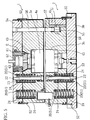
- FIG. 1 through Figure 3 show a preferred embodiment of a full enclosed forging apparatus of the present invention (a first preferred embodiment).
- this full enclosed forging apparatus provided with an upper die holder 1 directly attached to an upper attachment stage or a ram of a press machine and a lower die holder 2 attached to a lower attachment stage, the upper die holder 1 and the lower die holder 2 are respectively arranged upper and lower in the press machine as to face each other.
- Positioning of the upper die holder 1 and the lower die holder 2 is conducted by inserting a guiding rod 14, protruding from the lower die holder 2, to a guiding rod insertion hole 15 formed in the upper die holder 1 in working of the press machine.
- Main portion of the upper die holder 1 is composed of an upper holder base 5a fixed to an upper attachment stage or a ram of the press machine with bolts 39, an upper holder main body 4a, and spring mechanisms 20 between the upper holder base 5a and the upper holder main body 4a.
- the upper holder main body 4a is attached with bolts 19 as to move vertically for a predetermined distance of an aperture C, an upper die 3a is placed in a die fitting portion 43 formed on a central part of the upper holder main body 4a with a spacer 44, and an upper punch 9 is disposed on a center of the upper die 3a with a push up spring 45. And, the upper die 3a, placed in the die fitting portion 43 with the spacer 44, is fixed to the upper holder main body 4a through a die attachment member 46.
- a spring insertion hole 48 is formed along a peripheral portion of a flange 47 formed on a base end side of the upper punch 9, the push-up spring 45 is arranged in the spring insertion hole 48 as to contact an upper face of the upper die 3a through another spring insertion hole 49 formed on the spacer 44 of the upper die 3a, and the upper punch 9 is pushed upward thereby.
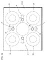
- the spring mechanism 20 between the upper holder base 5a and the upper holder main body 4a is disposed on four positions as to be symmetric with respect to the upper die 3a fixed to the upper holder main body 4a in the present embodiment.
- the spring mechanism 20 is composed of concentrically laminated plural belleville springs 21 fitted to a belleville spring holding body 23 fixed to the upper holder base 5a with a bolt 22, placed in a spring mechanism insertion hole 24 formed in the upper holder main body 4a, and pushing the upper holder main body 4a downward.
- the lower die holder 2 has basically similar construction to that of the upper die holder 1. That is to say, a main part of the lower die holder 1 is composed of a lower holder base 5b fixed to a lower attachment stage (bolster) of the press machine with bolts 39, a lower holder main body 4b, and spring mechanisms 20 between the lower holder base 5b and the lower holder main body 4b.
- the lower holder main body 4b is attached with bolts 19 as to move vertically for a predetermined distance of an aperture C, an upper die 3b is placed in a die fitting portion 43 formed on a central part of the lower holder main body 4b with a spacer 44, and an lower punch 10 is disposed on a center of the lower die 3b with a push-down spring 50. And, the lower die 3b, placed in the die fitting portion 43 with the spacer 44, is fixed to the lower holder main body 4b through a die attachment member 46.
- a spring insertion hole 48 is formed along a peripheral portion of a flange 47 formed on a base end side of the lower punch 10, the push-down spring 50 is arranged in the spring insertion hole 48 as to contact a lower face of the lower die 3b through another spring insertion hole 49 formed on the spacer 44 of the lower die 3b, and the lower punch 10 is pushed downward thereby.
- the spring mechanism 20 between the lower holder base 5b and the lower holder main body 4b is disposed on four positions as to be symmetric with respect to the lower die 3b fixed to the lower holder main body 4b in the present embodiment.
- the spring mechanism 20 is composed of concentrically laminated plural belleville springs 21 fitted to a belleville spring holding body 23 fixed to the lower holder base 5b with a bolt 22, placed in a spring mechanism insertion hole 24 formed in the lower holder main body 4b, and pushing the lower holder main body 4b upward.
- the upper die holder 1 and the lower die holder 2 are attached to the press machine on an upper side and a lower side with the bolts 39 as to face each other.
- the upper die 3a and the upper punch 9 of a predetermined configuration are attached to the upper die holder 1
- the lower die 3b and the lower punch 10 of a predetermined configuration are attached to the lower die holder 2.
- a material to be formed is placed on the lower die 3b.
- the die holder 1 is descended with the upper die 3a by working of the press machine, the upper die 3a attached to the upper die holder 1 and the lower die 3b attached to the lower die holder 2 contact each other, the material placed on the lower die 3b is held between the upper die 3a and the lower die 3b as to conduct predetermined forging (left-half of Figure 1 (first movement)).
- the upper holder main body 4a and the lower holder main body 4b are pressed through the upper die 3a and the lower die 3b touching each other by descending the upper die holder 1 with the upper die 3a, the upper holder main body 4a relatively moves upward to the upper holder base 5a and the lower holder main body 4b relatively moves downward to the lower holder base 5b resisting against the pushing power of the belleville springs 21 of the upper and lower spring mechanisms 20 as to narrow the aperture C between the upper holder base 5a and the upper holder main body 4a of the upper die holder 1, and the aperture C between the lower holder base 5b and the lower holder main body 4b of the lower die holder 2.
- the upper punch 9 attached to the upper die holder 1 and the lower punch 10 attached to the lower die holder 2 proceed respectively into the upper die 3a and the lower die 3b, the material held between the upper die 3a and the lower die 3b is forged into a predetermined configuration (right-half of Figure 1 (second movement)).
- the maximum descending distance of the upper die holder 1 is 2C that the aperture C between the upper holder base 5a and the upper holder main body 4a of the upper die holder 1, and the aperture C between the lower holder base 5b and the lower holder main body 4b of the lower die holder 2 vanish after the upper die 3a and the lower die 3b contact the material.
- the upper die holder 1 is ascended with the upper die 3a, the aperture C between the upper holder base 5a and the upper holder main body 4a of the upper die holder 1, and the aperture C between the lower holder base 5b and the lower holder main body 4b of the lower die holder 2 are enlarged by pushing power of the belleville springs 21 of the upper and lower spring mechanisms 20 in a state that the upper die 3a contacts the lower die 3b and the formed product (the material forged into the predetermined configuration) is held between the upper die 3a and the lower die 3b, and, the upper holder main body 4a relatively moves downward to the upper holder base 5a and the lower holder main body 4b relatively moves upward to the lower holder base 5b.
- the upper die holder 1 is ascended with the upper die 3a further, the contact of the upper die 3a and the lower die 3b is released, the upper die 3a and the lower die 3b become open, and the formed product can be taken out of the die.
- the upper punch 9 and the lower punch 10 respectively part from the formed product by pushing power of the push-up spring 45 and the push-down spring 50, and return to initial positions.
- the upper and lower spring mechanisms 20 and the upper and lower punches 9 and 10 are disposed on both of the upper die holder 1 and the lower die holder 2 in the present embodiment, these mechanisms may be disposed on only one die holder, and the other die holder may be provided with only the die depending on configurations of the product.
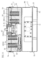
- FIG. 4 and Figure 5 show a second preferred embodiment of the present invention.
- This embodiment in which each of the plural spring mechanisms 20 is composed of a compression spring 51 disposed in an upper die holder 1 and a lower die holder 2 attached to a press machine, is provided with a synchronization mechanism G and a forged product release mechanism E.
- a die fitting portion 43 is formed on a central portion of a lower face of an upper holder main body 4a of the upper holder 1, and plural insertion holes 24 are formed on approximately whole upper face of the upper holder main body 4a of the upper holder 1 corresponding to surrounding area of the die fitting portion 43.
- Number of the insertion holes 24, determined corresponding to load on the upper holder main body 4a in forging and spring constant of the compression spring 51, is set as to receive the load on the upper holder main body 4a uniformly.
- insertion holes 24 are also formed on a lower face of an upper holder base 5a disposed above the upper holder main body 4a as to correspond to the insertion holes 24 formed on the upper holder main body 4a. Depth of the upper and lower insertion holes 24 is set as to hold the compression spring 51.
- the vertically laminated upper holder base 5a and the upper holder main body 4a are positioned by sliding guiding plates 52, attached to left and right end faces of the upper holder base 5a, on left and right end faces of the upper holder main body 4a, and by bolts 22 going through the compression springs 51 inserted to the insertion holes 24 of the upper holder main body 4a and the upper holder base 5a from the upper holder main body 4a side and screwed to the upper holder base 5a.
- the compression springs 51 are inserted to all of or some of the plural pairs of the upper and lower insertion holes 24.
- the bolt 22 can be omitted on a position where a (later described) synchronizing mechanism G, which synchronizes the upper die holder 1 and the lower die holder 2, is disposed. And, the bolt 22 may be covered by a sleeve 53 for protection of the bolt 22 and easy positioning of the upper holder base 5a and the upper holder main body 4a.
- the upper holder main body 4a is attached with an aperture C as to be movable vertically for a predetermined distance to the upper holder base 5a.
- the lower die holder 2 has a basically similar construction to that of the upper die holder 1. That is to say, a die fitting portion 43 is formed on an lower holder main body 4b, and plural insertion holes 24 are formed on approximately whole upper face of the lower holder main body 4b corresponding to surrounding area of the die fitting portion 43.
- Number of the insertion holes 24, determined corresponding to load on the lower holder main body 4b and spring constant of the compression spring 51 in forging, is set as to receive the load on the lower holder main body 4b uniformly.
- insert ion holes 24 are also formed on an upper face of an lower holder base 5b disposed below the lower holder main body 4b as to correspond to the insertion holes 24 formed on the lower holder main body 4b. Depth of the upper and lower insertion holes 24 is set as to hold the compression spring 51.
- the lower holder base 5b and the lower holder main body 4b are positioned by sliding guiding plates 52, attached to left and right end faces of the lower holder main body 4b, on left and right end faces of the lower holder base 5b, and by bolts 22 going through the compression springs 51 inserted to the insertion holes 24 of the lower holder main body 4b and the lower holder base 5b from the lower holder main body 4b side and screwed to the lower holder base 5b.
- the compression springs 51 are inserted to all of or some of the plural pairs of the upper and lower insertion holes 24.
- the bolt 22 can be omitted on a position where a (later described) synchronizing mechanism G, which synchronizes the upper die holder 1 and the lower die holder 2, is disposed. And, the bolt 22 may be covered by a sleeve 53 for protection of the bolt 22 and easy positioning of the upper holder base 5a and the upper holder main body 4a.
- the lower holder main body 4b is attached with an aperture C as to be movable vertically for a predetermined distance to the lower holder base 5b.
- the synchronization mechanism G is composed of a lever 55 supported by a shaft 54 in the lower holder main body 4b of the lower die holder 2 as to oscillate in a seesaw-like manner, a fixed rod 56 of which upper end is fixed to the upper holder base 5a and disposed as to go through the upper holder main body 4a, a sliding rod 57 facing a lower end face of the fixed rod 56 and touching an end side of the lever 55 inserted to the lower holder main body 4b, and a lever supporting piece 60, protruding upward from the lower holder base 5b, of which upper part is inserted to a hole 58 formed in the lower holder main body 4b as to slide, and having a cavity 59 formed on a side face to which the other end of the lever 55 fits to be stopped.
- the upper holder main body 4a descends from the state shown in Figure 7A to the state shown in Figure 7B by working of a press machine through the upper holder base 5a, the lower end of the fixed rod 56 fixed to the upper holder base 5a contacts and pushes the sliding rod 57 down, and the lever 55 oscillates in a seesaw-like manner of which supporting point is the shaft 54 thereby because the other end of the lever 55 is fitting to the cavity 59 on the lever supporting piece 60 and restricted.
- distance L 1 from the shaft 54 to a contact position of the lever 55 and the sliding rod 57 and distance L 2 from the shaft 54 to a fitting position of the lever 55 with the cavity 59 of the lever supporting piece 60 are set to be same.
- the other end of the lever 55 is fitted to the cavity 59 of the lever supporting piece 60 and restricted.
- the lower holder main body 4b is pushed down for descending amount S 2 which is 1/2 of descending amount S 0 of the upper holder base 5a to diminish an aperture C between the upper holder base 5a and the upper holder main body 4a and an aperture C between the lower holder base 5b and the lower holder main body 4b simultaneously for the same amount. That is to say, when the upper holder main body 4a descends for descending amount S 1 , the lower holder main body 4b descends for the descending amount S 2 equal to the descending amount S 1 synchronized with the upper holder main body 4a.
- the forged product release mechanism E has a construction in which a release mechanism main body 61 is embedded in the upper holder base 5a right above the upper die 3a and attached to the upper holder base 5a right above the upper die 3a with bolts, a piston 62 is inserted to a cylinder portion 63 formed in the release mechanism main body 61 as to push down lockout of the upper die 3a, and pressurized fluid (hydraulic oil, for example) is supplied into the cylinder portion 63.
- pressurized fluid hydroaulic oil, for example
- the pressurized fluid is supplied simultaneously when the upper die holder 1 ascends from the bottom dead point, and the forged product in the upper die 3a is forcibly released.
- a head side of the cylinder portion 63 may be tightly closed to contain gas which is compressed by the piston 62 when the upper holder base 5a is pushed down, and the piston 62 is pushed down by the pressure of the gas compressed in the ascension of the upper die holder 1 from the bottom dead point as to press down the lockout of the upper die 3a.
- the synchronization mechanism G and the forged product release mechanism E, described in the second preferred embodiment, are also applicable to the first preferred embodiment described above and the third preferred embodiment described below.
- Figure 8 shows a third preferred embodiment of the present invention.
- the spring mechanisms 20 are constructed as that two compression springs having different diameter are concentrically inserted to the plural pairs of upper and lower insertion holes 24 formed in the upper holder base 5a and the upper holder main body 4a, and the plural pairs of upper and lower insertion holes 24 formed in the lower holder main body 4b and the lower holder base 5b.
- elastic force of one unit of the spring mechanism 20 increases, and number of the spring mechanisms 20 and the insertion holes 24 can be reduced thereby.
- other constructions and working of the third preferred embodiment are similar to that of the full enclosed forging apparatus of the above-described second preferred embodiment.
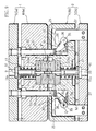
- FIG. 9 through Figure 11 show another embodiment of the full enclosed forging apparatus of the present invention.
- This full enclosed forging apparatus is provided with an upper die holder 1 and a lower die holder 2 disposed in a press machine as to face each other.
- the upper die holder 1 and the lower die holder 2 are respectively composed of a holder main body 4 holding a die 3, and a holder base 5 attached to the press machine.
- an upper holder base 5a is directly attached to an upper attachment stage or a ram of the press machine
- a lower holder base 5b is directly attached to a lower attachment stage of the press machine.
- 39 is a bolt with which the upper holder base 5a and the lower holder base 5b are attached to the press machine.
- hole portions are formed on a central portion of an upper holder main body 4a. That is to say, a large hole portion 6 for inserting an upper die 3a and a small hole portion 7 communicating with the large hole portion 6 are formed on a lower face side of the upper holder main body 4a.
- the upper die 3a is inserted to the large hole portion 6 and fixed with a holding member 8 fixed to the lower face side of the upper holder main body 4a.
- the lower die holder 2 similar to the upper die holder 1, a large hole portion 6 and a small hole portion 7 for inserting a lower die 3b are formed on an upper face side of a lower holder main body 4b, and the lower die 3b is inserted to the large hole portion 6 and fixed with a holding member 8.
- an upper punch 9 is disposed on a lower side of the upper holder base 5a and a lower punch 10 is disposed on an upper side of the lower holder base 5b, and the upper and lower punches 9 and 10 are held by upper and lower cylindrical holding bodies 11 each of which is attached to the upper and the lower holder bases 5a and 5b.
- the upper cylindrical holding body 11 is attached to a punch knock pin 42 protrudable downward from a lower face of the upper holder base 5a, and the lower cylindrical holding body 11 is attached to a die knock pin 41 protrudable upward from an upper face of the lower holder base 5b.
- an elastic member 17 is respectively disposed between an outer brim portion 11a of the upper cylindrical holding body 11 and the upper die 3a, and between an outer brim portion 11a of the lower cylindrical holding body 11 and the lower die 3b, and the upper punch 9 and the lower punch 10 are respectively pushed upward and downward through the cylindrical holding bodies 11. And, the upper punch 9 is inserted to a central hole portion 18 of the upper die 3a, and the lower punch 10 is inserted to a central hole portion 18 of the lower die 3b.
- a holding body insertion hole 40 which communicates with each of the central hole portions 18 is formed on an upper face side of the upper die 3a and a lower face side of the lower die 3b respectively, and cross-shaped forming die portions 12 and 13 which communicate with the central hole portions 18 are formed on a lower face side of the upper die 3a and an upper face side of the lower die 3b respectively.
- a pair of guiding rods 14 protrude upward from the lower holder main body 4b of the lower die holder 2 as to be symmetric with respect to the die 3
- insertion holes 15 for inserting the guiding rod 14 are formed in the upper holder main body 4a
- insertion holes 16 for inserting the guiding rod 14 are formed in the upper holder base 5a of the upper die holder 1. That is to say, in working of the press machine, position adjustment of the upper die holder 1 and the lower die holder 2 is conducted by inserting the guiding rods 14 to the insertion holes 15, and the upper die 3a and the lower die 3b are accurately closed thereby.
- the upper holder main body 4a is attached to the upper holder base 5a through plural units of spring mechanisms 20 retaining an aperture C for contraction of the spring mechanisms 20, and the lower holder main body 4b is attached to the lower holder base 5b through plural spring mechanisms 20 with an aperture C for contraction of the spring mechanisms 20.
- the upper holder main body 4a is attached to the upper holder base 5a through bolts 19 with the above aperture C with which the upper holder main body 4a can vertically move for a predetermined distance to the upper holder base 5a
- the lower holder main body 4b is attached to the lower holder base 5b with the aperture C with which the lower holder main body 4b can vertically move for a predetermined distance to the lower holder base 5b.
- a head portion of the bolt 19 restricts the movement of the holder main body 4 not to part from the holder base 5 for over the aperture C by hitching (through a washer, etc.) on a staged portion 34a of a bolt insert ion hole 34 formed on the holder main body 4.
- the above-described spring mechanism 20 is composed of concentrically laminated plural belleville springs 21 fitted to a belleville spring holding body 23 fixed to the upper holder base 5a with a bolt 22, placed in a spring mechanism insertion hole 24 formed in the upper holder main body 4a, and elastically pushing the upper holder main body 4a downward to the upper holder base 5a.
- a concave portion 24a, for escapement of the belleville spring holding body 23 in closing the die, is formed on a bottom portion of an insertion hole 24.
- the spring mechanism 20 is composed of concentrically laminated plural belleville springs 21 fitted to a spring holding body 23 fixed to the lower holder base 5b with a bolt 22, placed in a spring mechanism insertion hole 24 formed in the lower holder main body 4b, and elastically pushing the lower holder main body 4b upward to the lower holder base 5b.
- elastic force of the spring mechanism 20 of the lower die holder 2 side is set to be larger than that of the spring mechanism 20 of the upper die holder 1 side for 5% to 30% (preferably 8% to 20%).
- the plural spring mechanisms 20 are disposed to be symmetric with respect to the die 3, each of the upper die holder 1 and the lower die holder 2 is provided with four units of the spring mechanism 20 in the present embodiment.
- the upper punch 9 and the lower punch 10 can proceed into the die 3 after the contact of the upper die 3a and the lower die 3b held by the upper die holder 1 and the lower die holder 2 (described later in detail).
- the full enclosed forging apparatus of the present invention is provided with a punch uniform movement mechanism F, equivalent to the synchronization mechanism G described in the second preferred embodiment, which moves a lower end 9a of the upper punch 9 and an upper end 10a of the lower punch 10 toward a mating face position P of the upper and lower die 3a and 3b at an equal velocity.
- the punch uniform movement mechanism F is provided with a cam 26 disposed in a vacant chamber 25 formed in the lower holder main body 4b of the lower die holder 2, a cam holding member 27, of which lower end is attached to the lower holder base 5b and upper end is inserted to the vacant chamber 25, holding the cam 26 as to freely rotate, a sliding member 29 fixed to the vacant chamber 25 as to contact a first sliding portion 28 of the cam 26, and a push rod 31, of which upper end is attached to the upper holder base 5a of the upper die holder 1 and lower end is inserted to the vacant chamber 25 penetrating the upper holder main body 4a, contacts a second sliding portion 30 of the cam 26.
- an insertion hole 32 to which the push rod 31 is inserted, is formed in the upper holder main body 4a, a through hole 33 communicating with the vacant chamber 25 is formed on an upper face of the lower holder main body 4b, and a lower end of the push rod 31 is inserted into the vacant chamber 25 through the above insertion hole 32 and the through hole 33.
- the cam 26 is composed of a cylindrical portion 36 fitted to an arc groove 35 formed on an upper part of the cam holding member 27, and an oscillating piece 37 provided with a first sliding portion 28 having an arc portion and a second sliding portion 30 having an arc portion.
- the oscillating piece 37 oscillates up and down by rotation of the cylindrical portion 36 sliding on the arc groove 35.
- a pressing member 38 guided in vertical direction by a guiding mechanism not shown in Figures, is placed on the second sliding portion 30 of the oscillating piece 37 of the cam 26, and the lower end of the push rod 31 presses the oscillating piece 37 of the cam 26 through the pressing member 38.
- a sliding face which contacts the first sliding portion 28 of the cam 26 is formed to be inclined or concave.
- ratio of a distance R 1 , from a rotational center position Q of the cam 26 to a first contact position M of the first sliding portion 28 and the sliding member 29, to a distance R 2 , from the rotational center position Q of the cam 26 to a second contact position N of the second sliding portion 30 and the push rod 31, is set to be 1 : 2.
- the pressing member 38 is regarded as a part of the push rod 31 in forging because the push rod 31 contacts the second sliding portion 30 through the pressing member 38.
- plural units of the punch uniform movement mechanism F are disposed symmetrically with respect to the die 3, and a case that four units of the punch uniform movement mechanism F are disposed between the spring mechanisms 20 is shown in the present embodiment.
- the above pressing member 38 may be formed to be a ring shared by all units of the punch uniform movement mechanism F. In this case, a circular vacant portion, in which the ring-shaped pressing member 38 can vertically move, is formed in the lower holder main body 4b.
- the upper die holder 1 and the lower die holder 2 are attached to the press machine as to be vertically facing each other.
- the upper die 3a and the upper punch 9 of predetermined configurations are attached to the upper die holder 1
- the lower die 3b and the lower punch 10 of predetermined configurations are attached to the lower die holder 2 beforehand.
- the upper holder main body 4a and the lower holder main body 4b are pressed through the touching upper die 3a and lower die 3b by descending the upper die holder 1 with the upper die 3a, the upper holder main body 4a relatively moves upward to the upper holder base 5a and the lower holder main body 4b relatively moves downward to the lower holder base 5b resisting against the pushing force of the spring mechanisms 20 as to narrow the aperture C between the upper holder main body 4a and the upper holder base 5a, and the aperture C between the lower holder main body 4b and the lower holder base 5b.
- the upper punch 9 attached to the upper die holder 1 and the lower punch 10 attached to the lower die holder 2 proceed respectively into the upper die 3a and the lower die 3b, the material held between the upper die 3a and the lower die 3b is forged into a predetermined configuration (second movement).
- the push rod 31 descends for the same descending amount S 0 .
- the lower end of the push rod 31 presses the oscillating piece 31 of the cam 26 through the pressing member 38 to oscillate downward to a position of bottom dead point, the sliding member 29 is pressed by the oscillating piece 37, and the lower holder main body 4b descends (from a position shown with an imaginary line) for a predetermined descending amount S 2 .
- the lower punch 10 is relatively moved to approach the mating face position P of the upper die 3a and lower die 3b by descent of the upper and lower die 3a and 3b.
- V 4 V 2 .
- the upper punch 9 descends at the descending speed V 0 of the upper holder base 5a and approaches the contact face position P of the upper die 3a and lower die 3b.
- the approach speed of the upper punch 9 to the mating face position P is equal to the approach speed of the lower punch 10 to the mating face position P, and the lower end 9a of the upper punch 9 proceeds into the upper die 3a and the upper end 10a of the lower punch 10 proceeds into the lower die 3b approach the mating face position P of the upper die 3a and the lower die 3b at an equal speed.
- the upper die holder 1 is ascended with the upper die 3a, the aperture C between the upper holder base 5a and the upper holder main body 4a and the aperture C between the lower holder base 5b and the lower holder main body 4b are enlarged by pushing force of the belleville springs 21 of the spring mechanisms 20 in a state that the upper die 3a and the lower die 3b contact and hold the formed product, the upper holder main body 4a moves downward relatively to the upper holder base 5a, and the lower holder main body 4b moves upward relatively to the lower holder base 5b.
- the upper die holder 1 is ascended further with the upper die 3a, the contact of the upper die 3a and the lower die 3b is released, the upper die 3a and the lower die 3b are opened, the formed product is parted from the upper die 3a and the lower die 3b by the upper punch 9 and the lower punch 10 pushed by that the punch knock pin 42 and the die knock pin 41 are respectively pressed by rods on the press machine side with a slight delay, and takeout of the product is completed thereby (the formed product can be easily taken out of the die).
- the upper punch 9 and the lower punch 10 are parted from the formed product and returned to initial positions by pushing force of the elastic members 17.
- the cam 26 is always kept touching the sliding member 29 and the push rod 31 (the pressing member 38) in the closed state by setting the elastic force of the spring mechanism 20 of the lower die holder 2 side larger than the elastic force of the spring mechanism 20 of the upper die holder 1 side for 5 to 30%, and the approach movement speed V 5 of the upper punch 9 to the mating face position P of the die 3 can be surely equal to the approach movement speed V 4 of the lower punch 10 to the mating face position P thereby.
- the cam holding member 27 may be attached to the lower holder base 5b as to be adjustable in height to adjust the height of the cam 26 by adjusting the height of the cam holding member 27.
- a core bar can be disposed on the rotational center position Q of the cam 26 and attached to the cam holding member 27.
- the spring mechanism 20 may be composed of a compression spring instead of the belleville spring 21.
- the upper die holder 1 and the lower die holder 2 are moved simultaneously at the same speed and for the same amount in a basic motion, only one of the upper and lower die holders 1 and 2 can be moved (single closing) by fixing one of the holder main bodies to one of the die holders without double-action (in which both of the holder main bodies are moved).
- double-action forging can be conducted with a mechanism having a compact and simple construction.
- the belleville spring and the compression spring can be used for the spring mechanism.
- necessary pressure and distance for the double-action forging can be easily set by choice of the elastic modulus of the belleville spring and the compression spring, and by changing the number of the belleville spring and the compression spring.
- the apparatus has durability, and double-action forged product having a complicated configuration is easily and economically made even with a small single action press machine having a small die height.
- the double action is smoothly conducted by making the pressure and distance for the double-action forging uniform, and the double-action forging is conducted with high accuracy.
- the double action is smoothly conducted by making the pressure and distance for the double-action forging uniform with the spring mechanisms disposed symmetrically around the die, and the double-action forging is conducted with high accuracy.
- forging can be conducted with a compact and simple construction.
- the forging is conducted with high accuracy because the punch uniform movement mechanism moves the upper punch and the lower punch at the same speed to the mating face position of the die to press the material in the die.
- punch uniform movement mechanism having a relatively simple construction, is made easily.
- the cam is kept touching the sliding member and the push rod in forging, and the closing speed of the upper punch and the lower punch to the mating face position are certainly made equal thereby.
- the synchronization mechanism which synchronizes the descent of the lower holder main body of the lower die holder with the descent of the upper holder main body of the upper die holder, even in case that difference in forging resistance is generated between the upper die and the lower die, the upper and lower die holders are forced to move synchronously, the forging is conducted uniformly, and accuracy of the forged product is kept high.
- the forged product release mechanism which forcibly releases the forged product in the upper die is disposed in the upper holder base, the forged product in the upper die is released certainly and forcibly, and automatic forging is conducted smoothly.
Landscapes
- Engineering & Computer Science (AREA)
- Mechanical Engineering (AREA)
- Forging (AREA)
- Presses And Accessory Devices Thereof (AREA)
Applications Claiming Priority (4)
| Application Number | Priority Date | Filing Date | Title |
|---|---|---|---|
| JP35423698 | 1998-12-14 | ||
| JP35423698 | 1998-12-14 | ||
| JP12871199 | 1999-05-10 | ||
| JP12871199A JP3542738B2 (ja) | 1999-05-10 | 1999-05-10 | 閉塞鍛造装置 |
Publications (2)
| Publication Number | Publication Date |
|---|---|
| EP1016476A2 true EP1016476A2 (de) | 2000-07-05 |
| EP1016476A3 EP1016476A3 (de) | 2001-10-24 |
Family
ID=26464300
Family Applications (1)
| Application Number | Title | Priority Date | Filing Date |
|---|---|---|---|
| EP99124801A Withdrawn EP1016476A3 (de) | 1998-12-14 | 1999-12-13 | Schmiedevorrichtung mit völlig geschlossenem Gesenk |
Country Status (3)
| Country | Link |
|---|---|
| US (1) | US6260400B1 (de) |
| EP (1) | EP1016476A3 (de) |
| CN (1) | CN1118343C (de) |
Cited By (2)
| Publication number | Priority date | Publication date | Assignee | Title |
|---|---|---|---|---|
| CN118162620A (zh) * | 2024-05-16 | 2024-06-11 | 吉林省八方新材料科技有限公司 | 一种粉末整形装置 |
| CN118321477A (zh) * | 2024-06-13 | 2024-07-12 | 山西天宝集团有限公司 | 风力发电法兰锻造用智能加工台及其加工方法 |
Families Citing this family (7)
| Publication number | Priority date | Publication date | Assignee | Title |
|---|---|---|---|---|
| SE532183C2 (sv) * | 2007-09-28 | 2009-11-10 | Nord Lock Ab | Metod och anordning för tillverkning av brickor för låsning |
| DE102011102720B4 (de) | 2010-05-26 | 2021-10-28 | Ansaldo Energia Switzerland AG | Kraftwerk mit kombiniertem Zyklus und mit Abgasrückführung |
| CN102179464B (zh) * | 2011-03-25 | 2013-04-17 | 西安交通大学 | 一种汽车用发电机爪极成形工艺 |
| US9120138B2 (en) * | 2012-10-10 | 2015-09-01 | National Machinery Llc | Forged sideways extrusion |
| EP2950997B1 (de) * | 2013-02-01 | 2019-01-30 | Husky Injection Molding Systems Ltd. | Formsystem mit einstellbarer formschliesshöhe |
| ES2984220T3 (es) * | 2019-04-26 | 2024-10-29 | Proterial Ltd | Dispositivo de forja, y método para fabricar producto forjado |
| CN116274844B (zh) * | 2023-03-01 | 2023-10-20 | 江苏珀然股份有限公司 | 一种汽车轮毂锻造用固定装置 |
Family Cites Families (5)
| Publication number | Priority date | Publication date | Assignee | Title |
|---|---|---|---|---|
| US4274276A (en) * | 1978-07-31 | 1981-06-23 | Etablissement Supervis | Method and apparatus for producing a workpiece by extrusion molding |
| DE2927135B1 (de) * | 1979-07-05 | 1980-09-11 | Kabel Metallwerke Ghh | Verfahren und Vorrichtung zum Herstellen von Kegelzahnraedern |
| JPS59229298A (ja) * | 1983-05-25 | 1984-12-22 | Komatsu Ltd | プレス機械の金型装置 |
| JPS63220941A (ja) * | 1987-03-11 | 1988-09-14 | Aida Eng Ltd | 金型構造 |
| JPH0691339A (ja) * | 1992-09-14 | 1994-04-05 | Nagoya Giken Kogyo Kk | ジョイント金具用成形品の冷間圧造成形法 |
-
1999
- 1999-12-09 US US09/457,297 patent/US6260400B1/en not_active Expired - Fee Related
- 1999-12-13 EP EP99124801A patent/EP1016476A3/de not_active Withdrawn
- 1999-12-14 CN CN99126733A patent/CN1118343C/zh not_active Expired - Fee Related
Cited By (2)
| Publication number | Priority date | Publication date | Assignee | Title |
|---|---|---|---|---|
| CN118162620A (zh) * | 2024-05-16 | 2024-06-11 | 吉林省八方新材料科技有限公司 | 一种粉末整形装置 |
| CN118321477A (zh) * | 2024-06-13 | 2024-07-12 | 山西天宝集团有限公司 | 风力发电法兰锻造用智能加工台及其加工方法 |
Also Published As
| Publication number | Publication date |
|---|---|
| US6260400B1 (en) | 2001-07-17 |
| CN1256980A (zh) | 2000-06-21 |
| CN1118343C (zh) | 2003-08-20 |
| EP1016476A3 (de) | 2001-10-24 |
Similar Documents
| Publication | Publication Date | Title |
|---|---|---|
| US6260400B1 (en) | Full enclosed forging apparatus | |
| JPH0685955B2 (ja) | 閉塞鍛造装置 | |
| US12350729B2 (en) | Stamping dies and guided retainer devices for use in same | |
| US4346581A (en) | Apparatus for manufacturing fittings | |
| JP4139003B2 (ja) | 括れ部を有する製品の鍛造装置 | |
| US5241849A (en) | Drawing apparatus in the bedplate of a press | |
| JP3704261B2 (ja) | 複動用ダイホルダ機構 | |
| JPH0716749B2 (ja) | 閉塞鍛造装置 | |
| KR100597378B1 (ko) | 폐쇄단조장치 | |
| JP2002239675A (ja) | 閉塞鍛造金型装置 | |
| JPS61162237A (ja) | プレス機械の金型装置 | |
| JP3542738B2 (ja) | 閉塞鍛造装置 | |
| CN211161407U (zh) | 一种红冲机冲压装置 | |
| RU2011464C1 (ru) | Штамп для безоблойной объемной штамповки | |
| RU169362U1 (ru) | Штамп для горячей штамповки порошковых заготовок с отверстием | |
| WO2001083135B1 (en) | Method and impact machine for forming a body | |
| CN221454065U (zh) | 一种加工垫圈用的模具 | |
| JPH0339771B2 (de) | ||
| SU1731397A1 (ru) | Штамп дл объемной штамповки | |
| CN219151299U (zh) | 一体冲压模具 | |
| SU1731391A2 (ru) | Штамп дл безооблойной объемной штамповки | |
| SU1736669A1 (ru) | Штамп дл выдавливани заготовок | |
| SU1454564A1 (ru) | Штамп дл штамповки деталей из трубчатых заготовок | |
| SU814517A1 (ru) | Штамп дл разбортовки полых деталей | |
| SU1764756A1 (ru) | Штамп дл высадки на вертикальном прессе |
Legal Events
| Date | Code | Title | Description |
|---|---|---|---|
| PUAI | Public reference made under article 153(3) epc to a published international application that has entered the european phase |
Free format text: ORIGINAL CODE: 0009012 |
|
| AK | Designated contracting states |
Kind code of ref document: A2 Designated state(s): AT BE CH CY DE DK ES FI FR GB GR IE IT LI LU MC NL PT SE Kind code of ref document: A2 Designated state(s): DE FR GB |
|
| AX | Request for extension of the european patent |
Free format text: AL;LT;LV;MK;RO;SI |
|
| PUAL | Search report despatched |
Free format text: ORIGINAL CODE: 0009013 |
|
| AK | Designated contracting states |
Kind code of ref document: A3 Designated state(s): AT BE CH CY DE DK ES FI FR GB GR IE IT LI LU MC NL PT SE |
|
| AX | Request for extension of the european patent |
Free format text: AL;LT;LV;MK;RO;SI |
|
| RIC1 | Information provided on ipc code assigned before grant |
Free format text: 7B 21J 5/00 A, 7B 21J 13/03 B, 7B 21J 5/02 B |
|
| 17P | Request for examination filed |
Effective date: 20020225 |
|
| AKX | Designation fees paid |
Free format text: DE FR GB |
|
| 17Q | First examination report despatched |
Effective date: 20030714 |
|
| GRAP | Despatch of communication of intention to grant a patent |
Free format text: ORIGINAL CODE: EPIDOSNIGR1 |
|
| STAA | Information on the status of an ep patent application or granted ep patent |
Free format text: STATUS: THE APPLICATION IS DEEMED TO BE WITHDRAWN |
|
| 18D | Application deemed to be withdrawn |
Effective date: 20040713 |